torque ISUZU TROOPER 1995 Workshop Manual
[x] Cancel search | Manufacturer: ISUZU, Model Year: 1995, Model line: TROOPER, Model: ISUZU TROOPER 1995Pages: 1928
Page 884 of 1928
7A-12 AUTOMATIC TRANSMISSION (4L30-E)
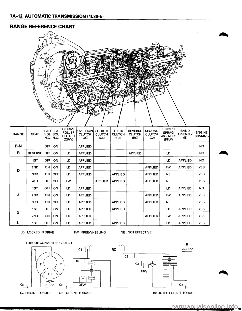
RANGE REFERENCE CHART
1-2/3-4 2-3 0/DRIVE OVERRUN FOURTH THIRD REVERSE SECOND BAND ROLLER ENGINE RANGE
GEAR SOL
SOL
CLUTCH CLUTCH
CLUTCH CLUTCH CLUTCH CLUTCH MBLY BRAKING N_c. N.O.
(OFW) (OCl
(C4)
(C3) (RC)
(C2) (B)
P-N OFF
ON APPLIED NO
R REVERSE OFF
ON LD APPLIED APPLIED LD NO
1ST OFF
ON LD APPLIED LD APPLIED NO
2ND ON ON LD APPLIED APPLIED FW APPLIED YES D 3RD ON
OFF LD APPLIED APPLIED APPLIED NE YES
4TH OFF OFF FW APPLIED APPLIED APPLIED NE YES
1ST OFF ON
LD APPLIED LD APPLIED NO
3 2ND ON ON LD APPLIED APPLIED FW APPLIED
YES
3RD ON OFF LD APPLIED APPLIED APPLIED NE YES
1ST OFF
ON LD APPLIED APPLIED LD APPLIED YES 2 2ND ON
ON LD APPLIED APPLIED FW APPLIED YES
L 1ST OFF
ON LD APPLIED APPLIED LD APPLIED
YES
LD : LOCKED IN DRIVE FW: FREEWHEELING NE : NOT EFFECTIVE
TORQUE CONVERTER CLUTCH
B
C4lil RC 1/f ~
C2 I I
C3
PFW ~
Qe OFW
Qe: ENGINE
TORQUE Qt: TURBINE TORQUE Qo: OUTPUT SHAFT TORQUE
Page 885 of 1928
AUTOMATIC TRANSMISSION (4L30-E) 7A-13
NORMAL OPERATION OF 1994-95 4L30-E TRANSMISSION
1. TORQUE CONVERTER CLUTCH (TCC)
APPLICATION CONDITIONS:
Engine coolant temperature must be above 70°C
(158°F).
Moreover, TCC is ON in 2nd gear during kick down
operation when engine coolant temperature is
above
70°C (158°F).
Also,
TCC is always ON in 2nd, 3rd & 4th gear when
transmission oil temperature is above 140°C
(284°F).
2. ATF WARNING LAMP
The ATF warning lamp will be constantly on (not
flashing) if the transmission oil temperature is
above
145°C (293°F).
The ATF warning lamp goes off again when the
transmission
oil temperature is below 125°C
(257°F).
3. SPECIAL SHIFT PATTERN WHEN THE
ENGINE IS COLD:
A special shift pattern is activated when the engine
coolant temperature is below 70°C (158°F). (3-4
shifts
for example are delayed for small throttle
openings and will occur a few MPH higher)
4. SHIFT ALTERATION WITH TECH1
DIAGNOSTIC TOOL CONNECTED:
Shifts will be harsh when TECH1 is connected to
TCM: Connection of TECH1 automatically forces
maximum line pressure during shifts only.
Page 896 of 1928
7 A-24 AUTOMATIC TRANSMISSION (4l30-E)
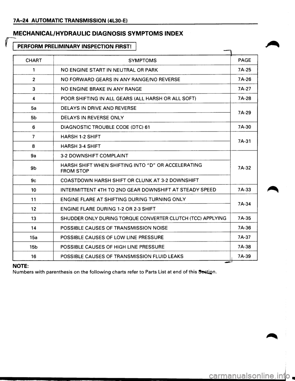
MECHANICAL/HYDRAULIC DIAGNOSIS SYMPTOMS INDEX
rr PERFORM PRELIMINARY INSPECTION FIRST! , -
CHART SYMPTOMS PAGE
1
NO ENGINE START IN NEUTRAL OR PARK 7A-25
2
NO FORWARD GEARS IN ANY RANGE/NO REVERSE 7A-26
3
NO ENGINE BRAKE IN ANY RANGE 7A-27
4
POOR SHIFTING IN ALL GEARS (ALL HARSH OR ALL SOFT) 7A-28
Sa DELAYS IN DRIVE AND REVERSE 7A-29
5b DELAYS
IN REVERSE ONLY
6 DIAGNOSTIC TROUBLE CODE (DTC) 61 7A-30
7 HARSH 1-2
SHIFT 7A-31
8 HARSH 3-4
SHIFT
9a 3-2 DOWNSHIFT
COMPLAINT
9b HARSH SHIFT WHEN SHIFTING INTO "D" OR ACCELERATING 7A-32 FROM STOP
9c COASTDOWN HARSH SHIFT OR CLUNK AT 3-2 DOWNSHIFT
10 INTERMITTENT 4TH TO 2ND GEAR DOWNSHIFT AT STEADY SPEED 7A-33
11 ENGINE FLARE AT SHIFTING
DURING TURNING ONLY 7A-34
12 ENGINE FLARE DURING 1-2 OR 2-3 SHIFT
13 SHUDDER ONLY DURING TORQUE CONVERTER CLUTCH (TCC) APPLYING 7A-35
14
POSSIBLE CAUSES OF TRANSMISSION NOISE 7A-36
15a
POSSIBLE CAUSES OF LOW LINE PRESSURE 7A-37
15b
POSSIBLE CAUSES OF HIGH LINE PRESSURE 7A-38
16
POSSIBLE CAUSES OF TRANSMISSION FLUID LEAKS It 7A-39
= -NOTE:
Numbers with parenthesis on the following charts refer to Parts List at end of this ~n.
•
Page 907 of 1928
AUTOMATIC TRANSMISSION (4L30-E) 7 A-35
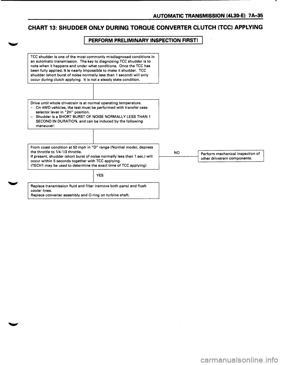
CHART 13: SHUDDER ONLY DURING TORQUE CONVERTER CLUTCH (TCC) APPLYING
PERFORM PRELIMINARY INSPECTION FIRST!
TCC shudder is one of the most commonly misdiagnosed conditions in
an automatic transmission. The key to diagnosing TCC shudder is to note when it happens and under what conditions. Once the TCC has
been fully applied, it is nearly impossible to make it shudder. TCC shudder {short burst of noise normally less than 1 second) will only
occur during clutch applying. It is not a steady state condition.
Drive
until whole drivetrain is at normal operating temperature.
-On 4WD vehicles, the test must be performed with transfer case selector lever in "2H" position.
- Shudder is a SHORT BURST OF NOISE NORMALLY LESS THAN 1
SECOND IN DURATION, and can be induced by the following maneuver:
From coast condition at
50 mph in "D" range {Normal mode), depress
the throttle to 1/4-1/3 throttle. If present, shudder {short burst of noise normally less than 1 sec.) will occur within 5 seconds together with TCC applying. {TECH1 may be used to determine the exact time of TCC applying)
YES
Replace transmission fluid and filter {remove both pans) and flush
cooler lines.
Replace
converter assembly and 0-ring on turbine shaft.
,__ __ N_o ___ ---<1 Perform mechanical inspection of I j other drivetrain components.
Page 912 of 1928
7 A-40 AUTOMATIC TRANSMISSION (4L30-E)
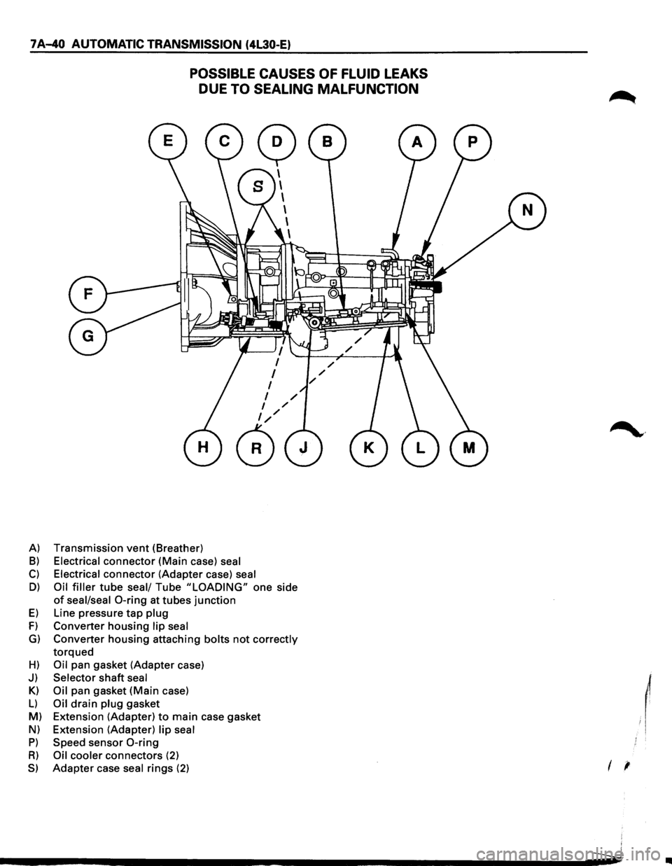
POSSIBLE CAUSES OF FLUID LEAKS
DUE
TO SEALING MALFUNCTION
A) Transmission vent (Breather)
B) Electrical connector (Main case) seal
C) Electrical connector (Adapter case) seal
D) Oil filler tube seal/ Tube "LOADING" one side
of seal/seal 0-ring at tubes junction
E) Line pressure tap plug
F) Converter housing lip seal
G) Converter housing attaching bolts not correctly
torqued
H) Oil pan gasket (Adapter case)
J) Selector shaft seal
Kl
Oil pan gasket (Main case)
L) Oil drain plug gasket
M) Extension (Adapter)
to main case gasket
Nl Extension (Adapter) lip seal
P) Speed sensor 0-ring
R) Oil cooler connectors (2)
S) Adapter case seal rings (2)
~·
I '
..
Page 913 of 1928
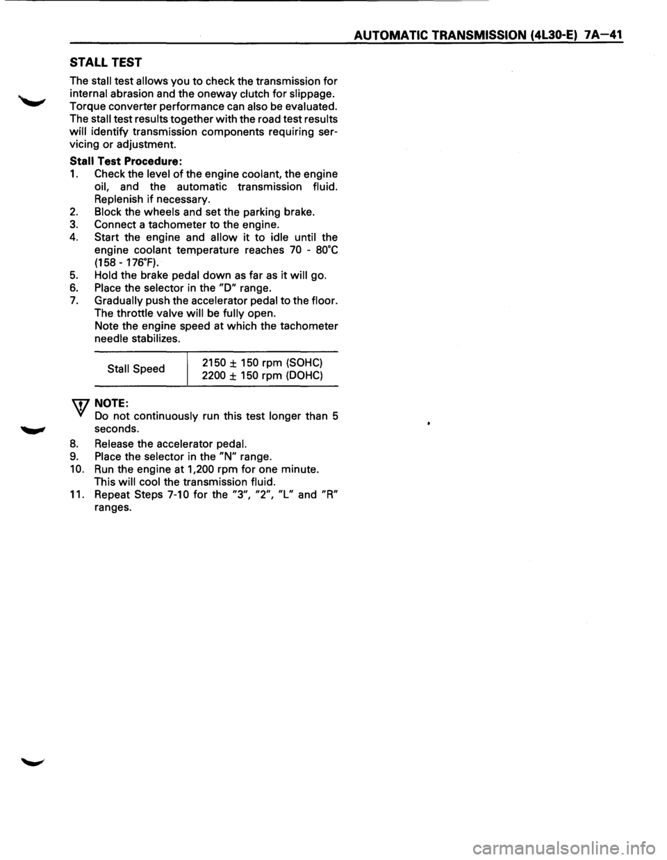
STALL TEST
The stall test allows you to check the transmission for
internal abrasion and the oneway clutch for slippage.
Torque converter performance can also be evaluated.
The
stall test results together with the road test results
will identify transmission components requiring ser
vicing or adjustment.
Stall Test Procedure:
1. Check the level of the engine coolant, the engine
oil, and the automatic transmission fluid.
Replenish
if necessary.
2. Block the wheels and set the parking brake.
3. Connect a tachometer to the engine.
4. Start the engine and allow it to idle until the
engine coolant temperature reaches
70 -8o·c
(158 -176.F).
5. Hold the brake pedal down as far as it will go.
6. Place the selector in the "D" range.
7. Gradually push the accelerator pedal to the floor.
The throttle valve
will be fully open.
Note the engine speed at which the tachometer
needle stabilizes.
Stall Speed
\fl NOTE:
2150 ± 150 rpm (SOHC)
2200 ± 150 rpm (DOHC)
VI Do not continuously run this test longer than 5
........, seconds.
8. Release the accelerator pedal.
9. Place the selector in the "N" range.
10. Run the engine at 1,200 rpm for one minute.
This
will cool the transmission fluid.
11. Repeat Steps 7-10 for the "3", "2", "L" and "R"
ranges.
AUTOMATIC TRANSMISSION (4L30-E) 7A-41
Page 914 of 1928
7 A-42 AUTOMATIC TRANSMISSION (4L30-E)
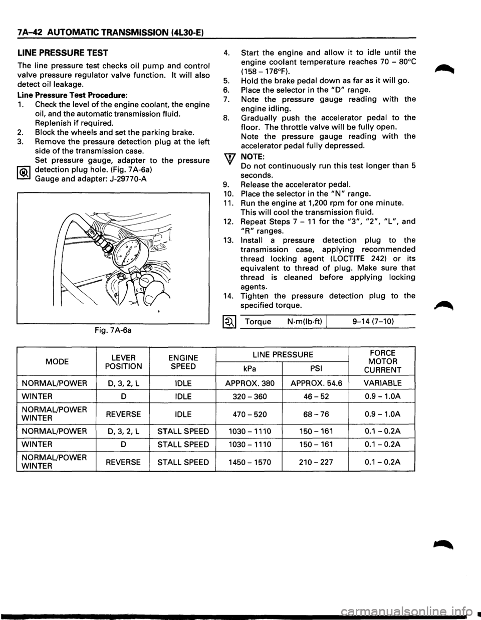
LINE PRESSURE TEST
The line pressure test checks oil pump and control
valve
pressure regulator valve function. It will also
detect oil leakage.
Line Pressure Test Procedure:
1. Check the level of the engine coolant, the engine
oil, and the automatic transmission fluid.
Replenish
if required.
2. Block the wheels and set the parking brake.
3. Remove the pressure detection plug at the left
side of the transmission case.
Set pressure gauge, adapter
to the pressure
l"iC\1 detection plug hole. (Fig. 7 A-6a)
~ Gauge and adapter: J-29770-A
Fig. 7A-6a
LEVER ENGINE
MODE
POSITION
SPEED
NORMAL/POWER D,3,2, L IDLE
WINTER D IDLE
NORMAL/POWER REVERSE IDLE WINTER
NORMAL/POWER
D,3,2,L STALL SPEED
WINTER D STALL SPEED
NORMAL/POWER REVERSE STALL SPEED WINTER
4.
5.
6.
7.
8.
9.
10.
11.
Start the engine and allow it to idle until the
engine
coolant temperature reaches 70 -80°C
(158-176°F).
Hold
the brake pedal down as far as it will go.
Place the selector in the "D" range.
Note the pressure gauge reading
with the
engine
idling.
Gradually
push the accelerator pedal to the
floor. The throttle valve will be fully open.
Note the pressure gauge reading
with the
accelerator
pedal fully depressed.
NOTE:
Do not continuously run this test longer than 5
seconds.
Release the accelerator pedal.
Place
the selector in the "N" range.
Run the engine at
1,200 rpm for one minute.
This
will cool the transmission fluid.
12. Repeat Steps 7-11 for the "3", "2", "L", and
"R" ranges.
13.
Install a pressure detection plug to the
transmission case,
applying recommended
thread
locking agent (LOCTITE 242) or its
equivalent to thread
of plug. Make sure that
thread is cleaned before applying locking
agents.
14. Tighten the pressure detection plug to the
specified torque.
~~~ Torque N·mOb·ft) / 9-14 (7-10)
LINE
PRESSURE FORCE
MOTOR kPa PSI CURRENT
APPROX. 380 APPROX. 54.6 VARIABLE
320-360 46-52 0.9 -1.0A
470-520 68-76 0.9 -1.0A
1030-1110 150-161 0.1-0.2A
1030-1110 150-161 0.1-0.2A
1450-1570 210-227 0.1-0.2A
•
Page 943 of 1928
AUTOMATIC TRANSMISSION (4L30-E) 7 A-71
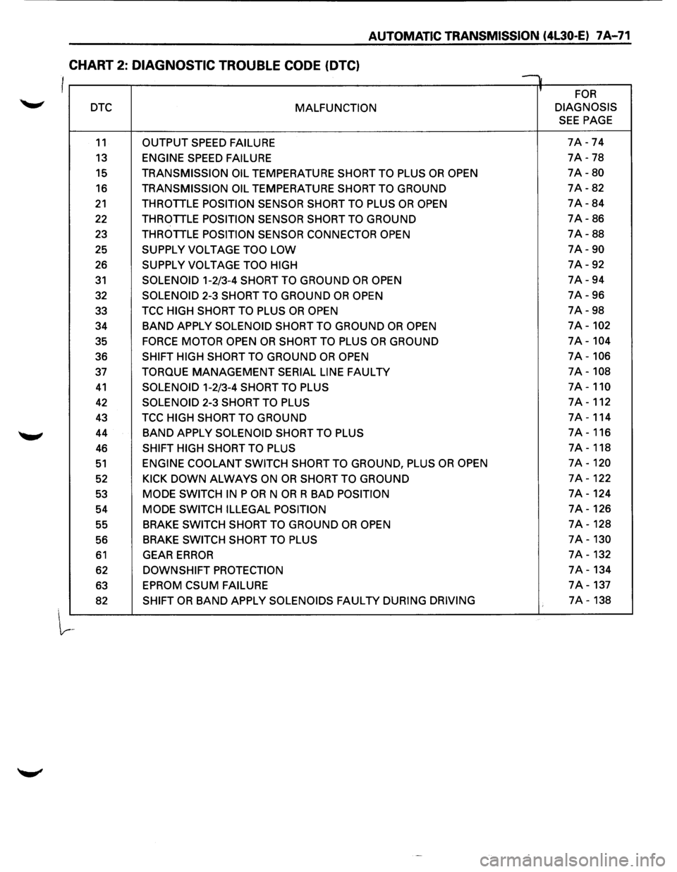
CHART 2: DIAGNOSTIC TROUBLE CODE (OTC)
I v
' FOR
DTC MALFUNCTION DIAGNOSIS
SEE PAGE
11 OUTPUT
SPEED FAILURE 7A -74
13 ENGINE SPEED FAILURE 7A -78
15 TRANSMISSION OIL TEMPERATURE SHORT TO PLUS OR OPEN 7A-80
16 TRANSMISSION OIL TEMPERATURE SHORT TO GROUND 7A-82
21 THROTTLE POSITION SENSOR SHORT TO PLUS OR OPEN 7A-84
22 THROTTLE POSITION SENSOR SHORT TO GROUND 7A-86
23 THROTTLE
POSITION SENSOR CONNECTOR OPEN 7A-88
25
SUPPLY VOLTAGE TOO LOW 7A-90
26 SUPPLY VOLTAGE TOO HIGH 7A-92
31 SOLENOID 1-2/3-4 SHORT TO GROUND OR OPEN 7A-94
32
SOLENOID 2-3 SHORT TO GROUND OR OPEN 7A-96
33 TCC
HIGH SHORT TO PLUS OR OPEN 7A-98
34
BAND APPLY SOLENOID SHORT TO GROUND OR OPEN 7A-102
35 FORCE MOTOR OPEN OR SHORT TO PLUS OR GROUND 7A-104
36 SHIFT HIGH SHORT TO GROUND OR OPEN 7A-106
37 TORQUE MANAGEMENT SERIAL LINE FAULTY 7A-108
41 SOLENOID 1-2/3-4 SHORT TO PLUS 7A-110
42 SOLENOID 2-3 SHORT TO PLUS 7A-112
43 TCC HIGH SHORT TO GROUND 7A-114
44
BAND APPLY SOLENOID SHORT TO PLUS 7A-116
46 SHIFT HIGH SHORT TO PLUS 7A-118
51 ENGINE COOLANT SWITCH SHORT TO GROUND, PLUS OR OPEN 7A-120
52 KICK DOWN ALWAYS ON OR SHORT TO GROUND 7A-122
53 MODE SWITCH IN P OR N OR R BAD POSITION 7A-124
54
MODE SWITCH ILLEGAL POSITION 7A-126
55 BRAKE
SWITCH SHORT TO GROUND OR OPEN 7A-128
56 BRAKE
SWITCH
SHORT TO PLUS 7A-130
61 GEAR ERROR 7A-132
62 DOWNSHIFT PROTECTION 7A-134
63
EPROM CSUM FAILURE 7A-137
82 SHIFT OR BAND APPLY SOLENOIDS FAULTY DURING DRIVING 7A-138
Page 970 of 1928
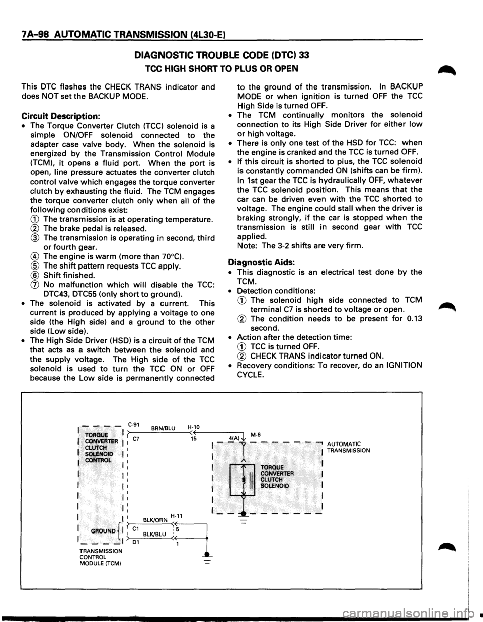
7 A-98 AUTOMATIC TRANSMISSION (4L30-E)
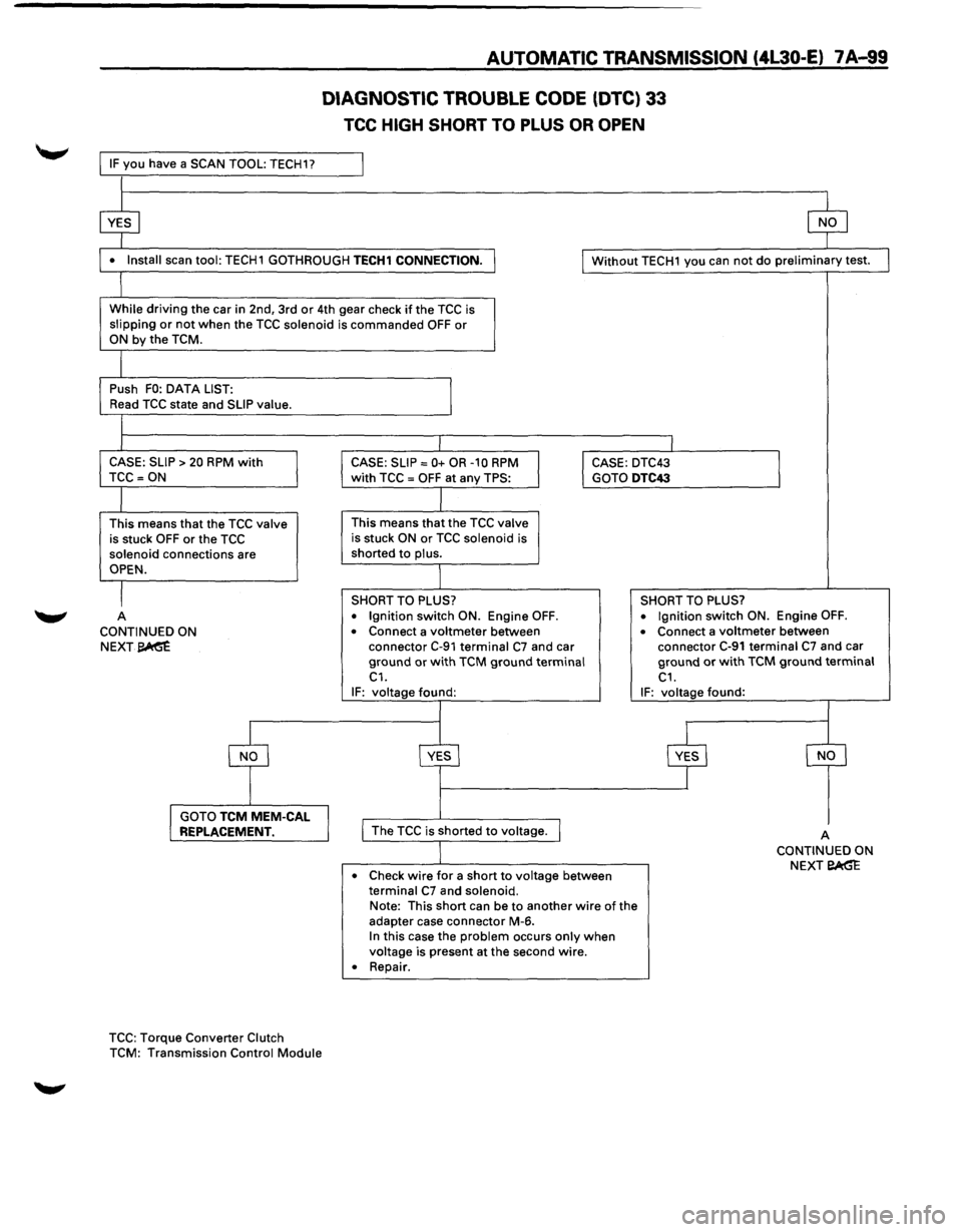
DIAGNOSTIC TROUBLE CODE (DTC) 33
TCC HIGH SHORT TO PLUS OR OPEN
This DTC flashes the CHECK TRANS indicator and
does NOT set the BACKUP MODE.
Circuit Description:
• The Torque Converter Clutch (TCC) solenoid is a
simple ON/OFF solenoid connected to the
adapter case valve body. When the solenoid is
energized
by the Transmission Control Module
(TCM), it opens a fluid port. When the port is
open,
line pressure actuates the converter clutch
control valve which engages the torque converter
clutch by exhausting the fluid. The TCM engages
the torque converter clutch only when all of the
following conditions exist:
G) The transmission is at operating temperature.
® The brake pedal is released.
® The transmission is operating in second, third
or fourth gear.
@ The engine is warm (more than 70°C).
® The shift pattern requests TCC apply.
® Shift finished.
(]) No malfunction which will disable the TCC:
DTC43, DTC55
(only short to ground).
• The solenoid is activated by a current. This
current is produced by applying a voltage to one
side (the High side) and a ground to the other
side (low side).
• The High Side Driver (HSD) is a circuit of the TCM
that acts as a switch between the solenoid and
the supply voltage. The High side of the TCC
solenoid is used to turn the TCC ON or OFF
because the Low side is permanently connected
to the ground of the transmission. In BACKUP
MODE
or when ignition is turned OFF the TCC
High Side is
turned OFF.
• The TCM continually monitors the solenoid
connection to its High Side Driver for either low
or high voltage.
• There is only one test of the HSD for TCC: when
the engine is cranked and the TCC is turned OFF.
•
If this circuit is shorted to plus, the TCC solenoid
is constantly commanded ON (shifts can be firm).
In 1st gear the TCC is hydraulically OFF, whatever
the TCC solenoid position. This means that the
car can be driven even with the TCC shorted to
voltage. The engine could stall when the driver is
braking strongly, if the car is stopped when the
transmission is still in second gear with TCC
applied. Note: The 3-2
shifts are very firm.
Diagnostic Aids:
• This diagnostic is an electrical test done by the
TCM.
• Detection conditions:
G) The solenoid high side connected to TCM
terminal C7 is shorted to voltage or open.
® The condition needs to be present for 0.13
second.
• Action after the detection time:
G) TCC is turned OFF.
® CHECK TRANS indicator turned ON.
•
Recovery conditions: To recover, do an IGNITION
CYCLE.
I - - - -C-91 BRN/BLU H-10
TOFlQU!;
I ? (( 4(A) J., M-6
I Cot!M:R'teR I I c7 15 I --1· -.-- - - ---. AUTOMATIC .. CLU'IrlilH I I S~NOib I I I TRANSMISSION
leoti~~~~ I . I I T()ftotJE
I I I I II CoHVEMER I I ' CLUTCH I I I I SQLENOID I
I 1: I I
I II I I I
I I H-11 - --!._-- - - - - -
{ I
{
BLK/ORN ~
9
-=-
1 GROUND I I C1 BLK/BLU : 5
1_--_,) 01 ( 1
TRANSMISSION
CONTROL MODULE (TCM)
•
Page 971 of 1928
IF you have a SCAN TOOL: TECH1?
L
$
AUTOMATIC TRANSMISSION (4L30-E) 7 A-99
DIAGNOSTIC TROUBLE CODE (OTC) 33
TCC HIGH SHORT TO PLUS OR OPEN
$
• Install scan tool: TECH1 GOTHROUGH TECH1 CONNECTION. I I Without TECH1 you can not do preliminary test.
l
While driving the car in 2nd, 3rd or 4th gear check if the TCC is
slipping or not when the TCC solenoid is commanded OFF or ON by the TCM.
I
Push FO: DATA LIST:
I Read TCC state and SLIP value.
l I I
CASE: SLIP > 20 RPM with CASE: SLIP= 0+ OR -10 RPM I CASE: DTC43
I TCC =ON with TCC = OFF at any TPS: GOTO DTC43
I
This means that the TCC valve This means that the TCC valve
is stuck OFF or the TCC is stuck ON or TCC solenoid is
solenoid connections are shorted to plus.
OPEN.
I SHORT TO PLUS? SHORT TO PLUS?
A
• Ignition switch ON. Engine OFF. • Ignition switch ON. Engine OFF.
CONTINUED ON • Connect a voltmeter between • Connect a voltmeter between
NEXT~ connector C-91 terminal C7 and car connector C-91 terminal C7 and car
ground or with TCM ground terminal ground or with TCM ground terminal C1. C1. IF: voltage found: IF: voltage found:
~
YES
$ s
I GOTO TCM MEM-CAL REPLACEMENT. I I The TCC is shorted to voltage. I A CONTINUED ON
Check
wire for a short to voltage between NEXT eAG"E • terminal C7 and solenoid. Note:
This short can be to another wire of the
adapter case connector M-6.
In this case the problem occurs only when voltage is present at the second wire.
• Repair .
TCC: Torque Converter Clutch
TCM: Transmission Control Module