torque ISUZU TROOPER 1995 Workshop Manual
[x] Cancel search | Manufacturer: ISUZU, Model Year: 1995, Model line: TROOPER, Model: ISUZU TROOPER 1995Pages: 1928
Page 687 of 1928
-
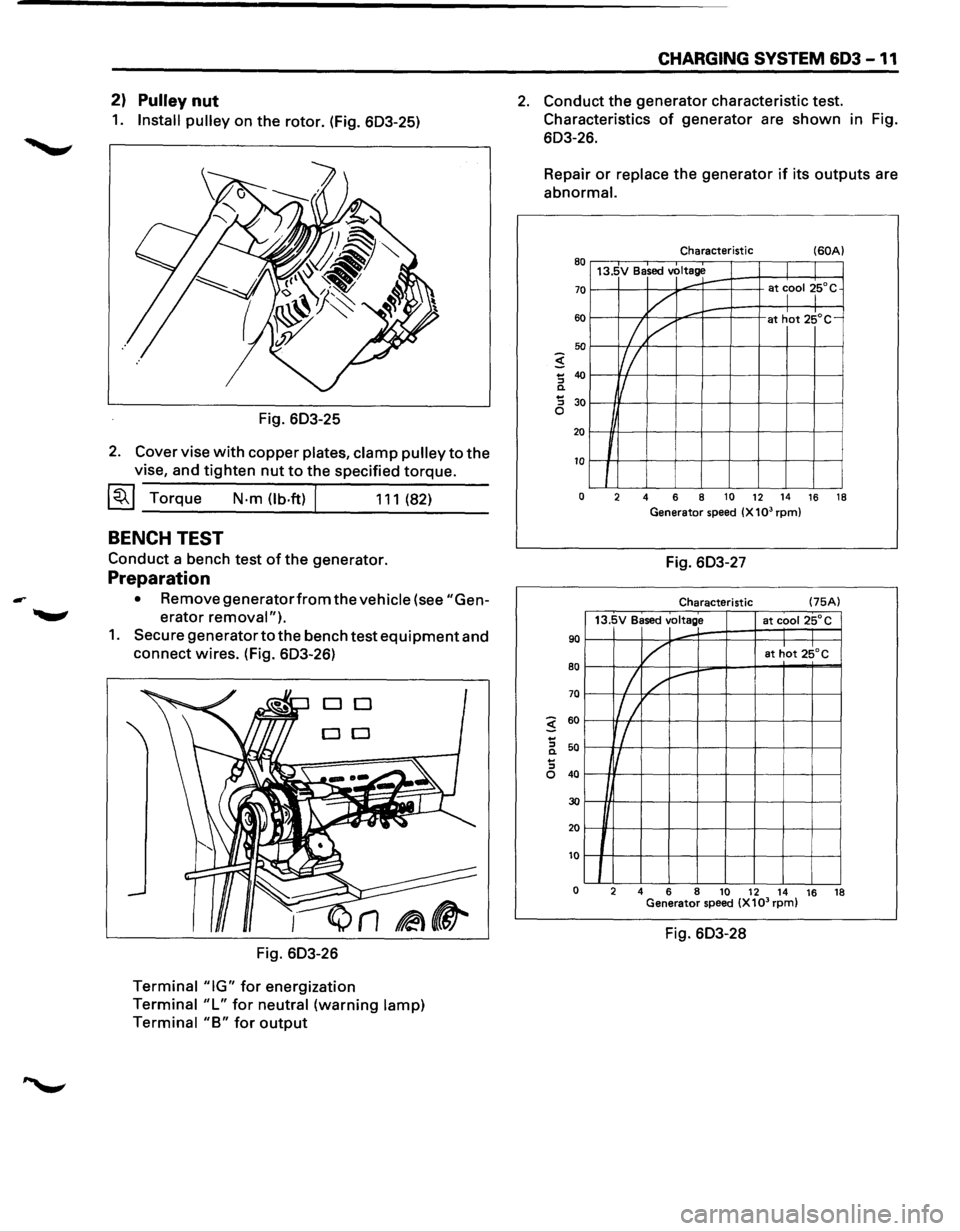
2) Pulley nut
1. Install pulley on the rotor. (Fig. 603-25)
Fig. 603-25
2. Cover vise with copper plates, clamp pulley to the
vise, and tighten nut to the specified torque.
~~~Torque N-m(lb.ft) 111(82)
BENCH TEST
Conduct a bench test of the generator.
Preparation
• Remove generatorfrom the vehicle (see "Gen
erator removal").
1. Secure generator to the bench test equipment and
connect wires. (Fig. 603-26)
DO
DO
Fig. 603-26
Terminal "IG" for energization
Terminal "L" for neutral (warning lamp)
Terminal
"B" for output
CHARGING SYSTEM 603 -11
2. Conduct the generator characteristic test.
Characteristics
of generator are shown in Fig.
603-26.
Repair
or replace the generator if its outputs are
abnormal.
Characteristic (60A) 80 13.5V Based voltage
70
60
50
5 ... 40 "' c. ... 30 "'
......... r-at lool ~5°C
v ,........
/, /
at hot 25°C-
Iff_
f/
0
20
10
J 0 2 4 6 8 10 12 14 16 18
Generator speed (X 103 rpm)
Fig. 603-27
Characteristic (75A)
13.5V Based
voltage at cooi25°C
90
80
70
5 60
...
"' 50 c. ...
v at hot 25°C
I / ~
l/ /
r/
I
"' 0 40
30
20
10
0 2
4 6
8
10 12 14 16
18
Generator speed (X103 rpm)
Fig. 603-28
Page 689 of 1928
IGNITION SYSTEM 6D4 - 1
SECTION 604
IGNITION SYSTEM
CONTENTS
General Description ...................... .
Diagnosis
................................... .
On-Vehicle Service ....................... .
Spark Plug Wire ....................... .
Spark Plug .............................. . 6D4-1
6D4-2 6D4-3
6D4-3
6D4-3
Electronic Ignition (EI) Assembly ...
Crankshaft Position Sensor
(CKP sensor) ........................ .
Torque Specifications
................ .
Main Data and Specifications
......... . 6D4-5
6D4-5
6D4-6
6D4-7
GENERAL DESCRIPTION
Ignition is done by the Electronic Ignition (EI) that
fires directly the ignition plugs from ignition coils
through spark plug wires without using a distributor.
A pair of ignition coils for the cylinders having differ
ent phases by 360° (No.1 and No.4, No.2 and No.5,
No.3 and No.6) are
fired simultaneously.
Since the cylinder on exhaust stoke requires less
energy to fire its ignition plug, energy from the
ignition coils can be utilized to fire the mating cylin
der on compression stroke. After additional 360°
rotation, respective cylinder stokes are reversed.
TheEl consists of three ignition coils, ignition control
module, crank angle sensor, Engine Control Module
(ECM) and other components.
Module is provided under the ignition coil, connected
with ECM by means of 6-pin connector. The
ignition control module turns on/off the primary
circuit of ignition coils, and also it controls the igni
tion timing at the engine
speed below 538 rpm.
A notch in
the timing disc on the crankshaft activates
the crank angle sensor which then sends information
such as firing order and starting timing of each
ignition coil to the ECM.
Further, the El employs Ignition Control (I C) to control
similar to a distributor system.
By receiving
signals such as crank position, engine
speed, water temperature and Manifold Absolute
Pressure (MAP), the ECM controls the ignition timing.
Page 693 of 1928
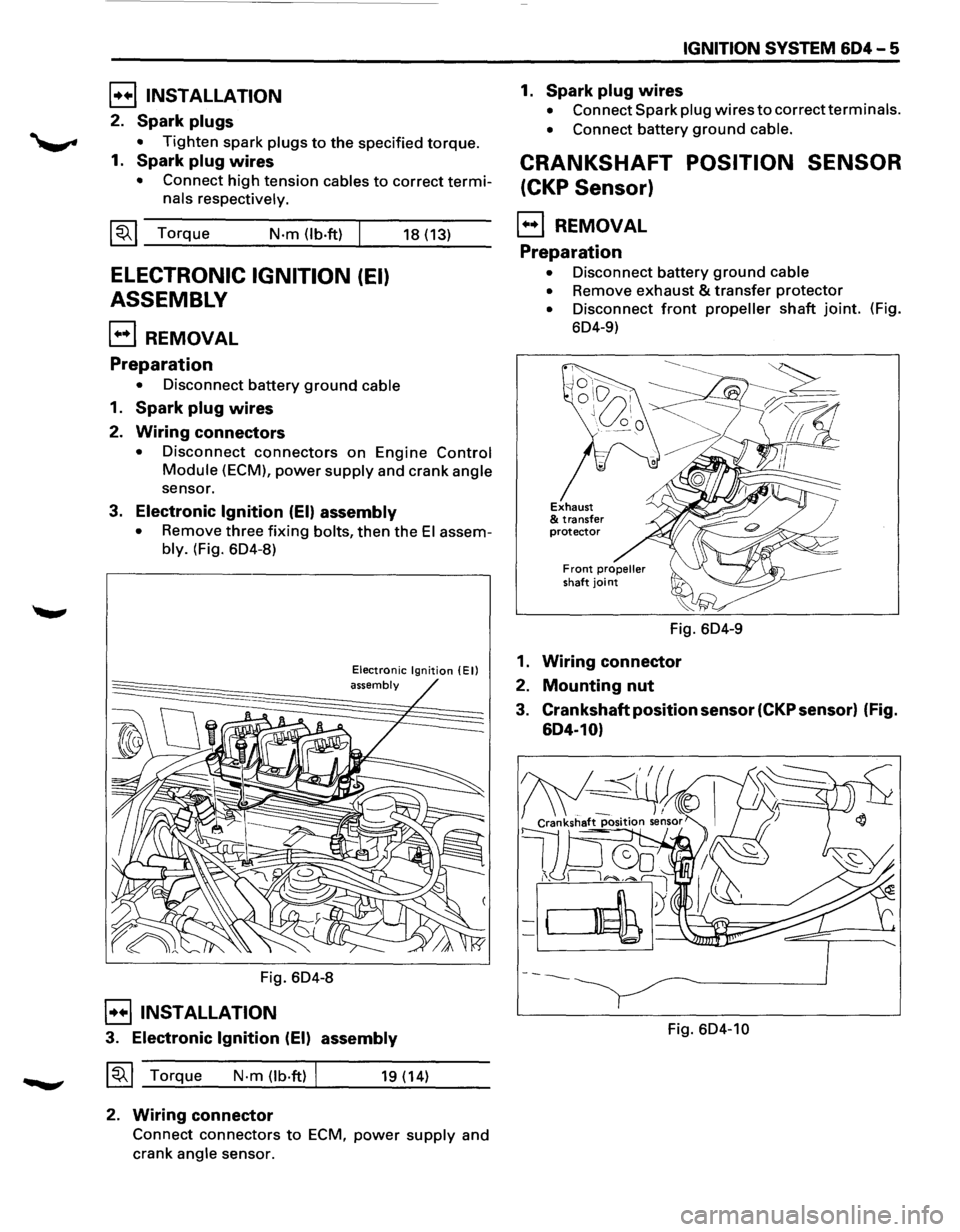
[!!) INSTALLATION
2. Spark plugs
• Tighten spark plugs to the specified torque.
1. Spark plug wires
• Connect high tension cables to correct termi
nals respectively.
~~~ Torque N·m (lb·ft) I
ELECTRONIC IGNITION (EI)
ASSEMBLY
EJ REMOVAL
Preparation
• Disconnect battery ground cable
1. Spark plug wires
2. Wiring connectors
18 (13)
• Disconnect connectors on Engine Control
Module (ECM), power supply and crank angle
sensor.
3. Electronic Ignition (EI) assembly
• Remove three fixing bolts, then the El assem
bly. (Fig. 6D4-8)
Fig. 6D4-8
E]INSTALLATION
Electronic Ignition (Ell assembly
3. Electronic Ignition (EI) assembly
~~~ Torque N·m (lb·ftl I 19 (14)
2. Wiring connector
Connect connectors to ECM, power supply and
crank
angle sensor.
IGNITION SYSTEM 604-5
1. Spark plug wires
• Connect Spark plug wires to correct terminals.
• Connect battery ground cable.
CRANKSHAFT POSITION SENSOR
(CKP Sensor)
E) REMOVAL
Preparation
• Disconnect battery ground cable
•
Remove exhaust & transfer protector
• Disconnect front propeller shaft joint. (Fig.
6D4-9)
Fig. 6D4-9
1. Wiring connector
2. Mounting nut
3. Crankshaft position sensor (CKP sensor) (Fig.
604-10)
Fig. 6D4-10
Page 694 of 1928
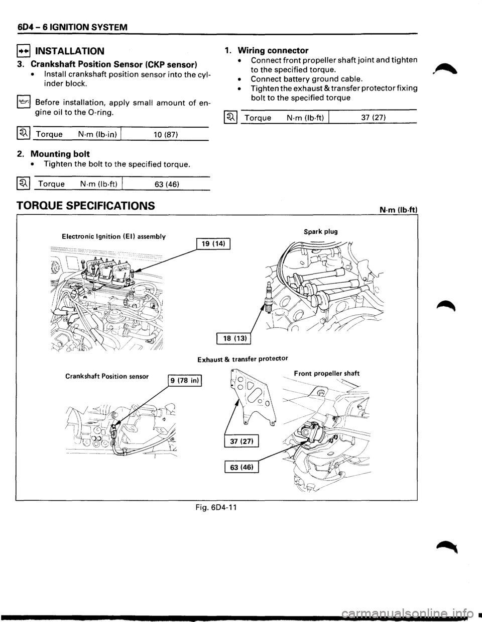
604-6 IGNITION SYSTEM
B INSTALLATION
3. Crankshaft Position Sensor (CKP sensor)
• Install crankshaft position sensor into the cyl
inder block.
1~1 Before installation, apply small amount of en
gine oil to the 0-ring.
~~~ Torque N-m (lb-in) I 10 (87)
2. Mounting bolt
• Tighten the bolt to the specified torque.
~~~ Torque N-m (lb·ft) I 63 (46)
TORQUE SPECIFICATIONS
Electronic Ignition (EI) assembly
1. Wiring connector
• Connect front propeller shaft joint and tighten
to the specified torque.
• Connect battery ground cable.
•
Tighten the exhaust & transfer protector fixing
bolt to the specified torque
~~~ Torque N-m (lb·ft) 37 (27)
N·m (lb·ftl
Spark plug
Exhaust & transfer protector
Crankshaft Position sensor
Fig. 604-11
•
Page 695 of 1928
IGNITION SYSTEM 604-7
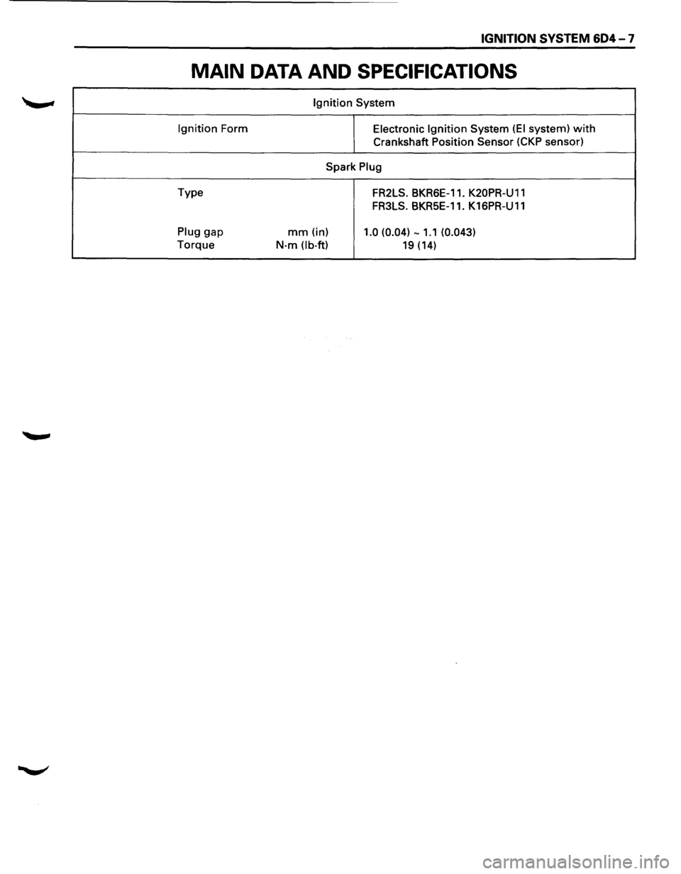
MAIN DATA AND SPECIFICATIONS
Ignition System
Ignition Form Electronic Ignition System (EI system) with
Crankshaft Position Sensor (CKP sensor)
Spark
Plug
Type FR2LS. BKRSE-11. K20PR-U 11
FR3LS. BKRSE-11. K 16PR-U 11
Plug gap mm (in) 1.0 (0.04) -1.1 (0.043)
Torque N·m Ob·ft) 19 (14)
Page 708 of 1928
6E2-12 DRIVEABILITY AND EMISSIONS
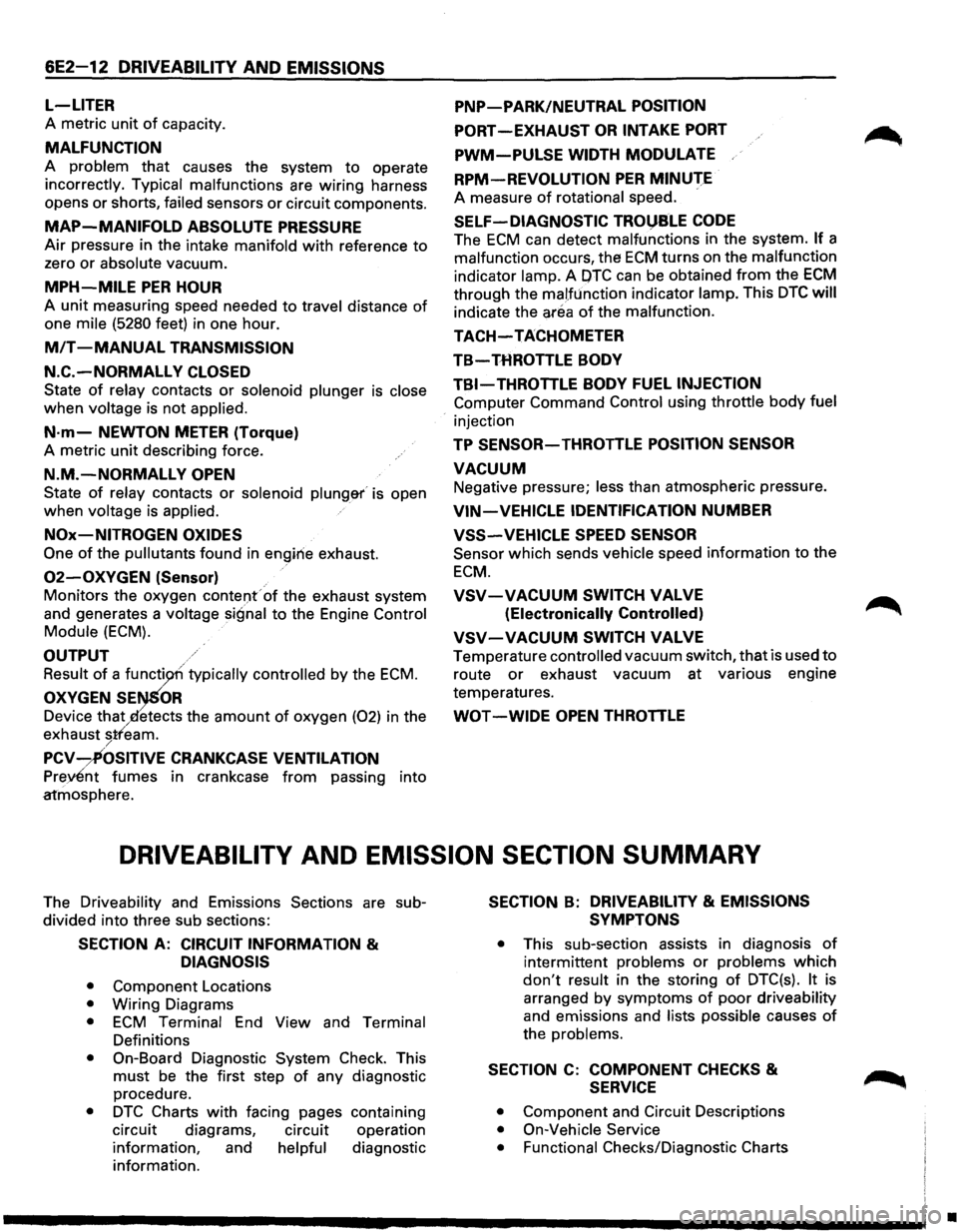
L-LITER
A metric unit of capacity.
MALFUNCTION
A problem that causes the system to operate
incorrectly. Typical malfunctions are wiring harness
opens
or shorts, failed sensors or circuit components.
MAP-MANIFOLD ABSOLUTE PRESSURE
Air pressure in the intake manifold with reference to
zero or absolute vacuum.
MPH-MILE PER HOUR
A unit measuring speed needed to travel distance of
one mile (5280 feet) in one hour.
MIT -MANUAL TRANSMISSION
N.C.-NORMALLY CLOSED
State of relay contacts or solenoid plunger is close
when voltage is not applied.
N·m-NEWTON METER (Torque)
A metric unit describing force.
N.M.-NORMALLY OPEN
State of relay contacts or solenoid plung&r' is open
when voltage is applied.
NOx-NITROGEN OXIDES
One of the pullutants found in engirie exhaust.
02-0XYGEN (Sensor)
Monitors the oxygen contel)f of the exhaust system
and generates a
voltage signal to the Engine Control
Module (ECM).
OUTPUT
Result of a functi typically controlled by the ECM.
OXYGEN SE OR
Device that etects the amount of oxygen (02) in the
exhaust
stfeam. /
PCV-~OSITIVE CRANKCASE VENTILATION
Prey£nt fumes in crankcase from passing into
atmosphere.
PNP-PARK/NEUTRAL POSITION
PORT-EXHAUST OR INTAKE PORT
PWM-PULSE WIDTH MODULATE
RPM-REVOLUTION PER MINUTE
A measure of rotational speed.
SELF-DIAGNOSTIC TROl)SLE CODE
The ECM can detect malfunctions in the system. If a
malfunction occurs, the ECM turns on the malfunction
indicator lamp. A OTC can be obtained from the ECM
through the malfunction indicator lamp. This DTC will
indicate the area of the malfunction.
TACH-TACHOMETER
TB-THROTTLE BODY
TBI-THROTTLE BODY FUEL INJECTION
Computer Command Control using throttle body fuel
injection
TP SENSOR-THROTTLE POSITION SENSOR
VACUUM
Negative pressure; less than atmospheric pressure.
VIN-VEHICLE IDENTIFICATION NUMBER
VSS-VEHICLE SPEED SENSOR
Sensor which sends vehicle speed information to the
ECM.
VSV-VACUUM SWITCH VALVE
(Electronically Controlled)
VSV-VACUUM SWITCH VALVE
Temperature controlled vacuum switch, that is used to
route or exhaust vacuum at various engine
temperatures.
WOT -WIDE OPEN THROTTLE
DRIVEABILITV AND EMISSION SECTION SUMMARY
The Driveability and Emissions Sections are sub
divided into three sub sections:
SECTION A: CIRCUIT INFORMATION &
DIAGNOSIS
• Component Locations
• Wiring Diagrams
• ECM Terminal End View and Terminal
Definitions
• On-Board Diagnostic System Check. This
must be the first step of any diagnostic
procedure.
• DTC Charts with facing pages containing
circuit diagrams, circuit operation
information, and
helpful diagnostic
information.
SECTION B: DRIVEABILITY & EMISSIONS
SYMPTONS
• This sub-section assists in diagnosis of
intermittent problems or problems which
don't result in the storing of DTC(s). It is
arranged
by symptoms of poor driveability
and emissions and lists possible causes of
the problems.
SECTION C: COMPONENT CHECKS &
SERVICE
• Component and Circuit Descriptions
• On-Vehicle Service
• Functional
Checks/Diagnostic Charts
•
Page 753 of 1928
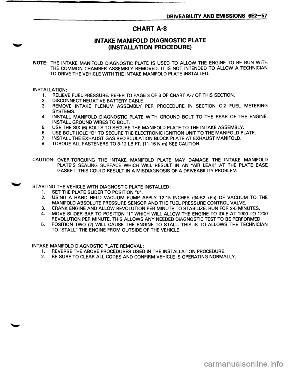
DRIVEABILITY AND EMISSIONS 6E2-57
CHART A-8
INTAKE MANIFOLD DIAGNOSTIC PLATE
(INSTALLATION PROCEDURE)
NOTE: THE INTAKE MANIFOLD DIAGNOSTIC PLATE IS USED TO ALLOW THE ENGINE TO BE RUN WITH
THE COMMON CHAMBER ASSEMBLY REMOVED. IT IS NOT INTENDED TO ALLOW A TECHNICIAN
TO
DRIVE THE VEHICLE WITH THE INTAKE MANIFOLD PLATE INSTALLED.
INSTALLATION:
1. RELIEVE FUEL PRESSURE. REFER TO PAGE 3 OF 3 OF CHART A-7 OF THIS SECTION.
2. DISCONNECT NEGATIVE BATTERY CABLE.
3. REMOVE INTAKE PLENUM ASSEMBLY PER PROCEDURE IN SECTION C-2 FUEL METERING
SYSTEMS.
4. INSTALL MANIFOLD DIAGNOSTIC PLATE WITH GROUND BOLT TO THE REAR OF THE ENGINE.
INSTALL
GROUND WIRES TO BOLT.
5. USE THE SIX (6) BOLTS TO SECURE THE MANIFOLD PLATE TO THE INTAKE ASSEMBLY.
6. USE BOLT HOLE "D" TO SECURE THE ELECTRONIC IGNITION UNIT TO THE MANIFOLD PLATE.
7. INSTALL THE EXHAUST GAS RECIRCULATION BLOCK PLATE AT EXHAUST MANIFOLD.
8. TORQUE ALL FASTENERS TO 8-12 LB.FT. (11-16 N·m) SEE CAUTION.
CAUTION: OVER-TORQUING
THE INTAKE MANIFOLD PLATE MAY DAMAGE THE INTAKE MANIFOLD
PLATE'S SEALING SURFACE WHICH WILL RESULT IN AN "AIR LEAK" AT THE PLATE BASE
GASKET. THIS COULD RESULT IN A MISDIAGNOSIS OF A DRIVEABILITY PROBLEM.
STARTING THE VEHICLE WITH DIAGNOSTIC PLATE INSTALLED:
1. SET THE PLATE SLIDER TO POSITION "0".
2. USING A HAND HELD VACUUM PUMP APPLY 12-15 INCHES (34-52 kPa) OF VACUUM TO THE
MANIFOLD ABSOLUTE PRESSURE SENSOR AND THE FUEL PRESSURE CONTROL VALVE.
3. CRANK ENGINE AND ALLOW REVOLUTION PER MINUTE TO STABILIZE. RUN FOR 2-5 MINUTES.
4. MOVE SLIDER BAR TO POSITION "1" WHICH WILL ALLOW THE ENGINE TO IDLE AT 1000 TO 1200
REVOLUTION
PER MINUTE. THIS ALLOWS ANY NEEDED DIAGNOSTIC TEST TO BE PERFORMED.
5. POSITION TWO (2) WILL CAUSE THE ENGINE TO STALL. THIS IS TO ALLOWS THE TECHNICIAN
TO "STALL"
THE ENGINE FROM OUTSIDE OF THE VEHICLE.
INTAKE MANIFOLD DIAGNOSTIC
PLATE REMOVAL:
1. REVERSE THE ABOVE PROCEDURES USED IN THE INSTALLATION PROCEDURE.
2. BE SURE TO CLEAR ALL CODES AND CONFIRM VEHICLE IS OPERATING NORMALLY.
Page 788 of 1928
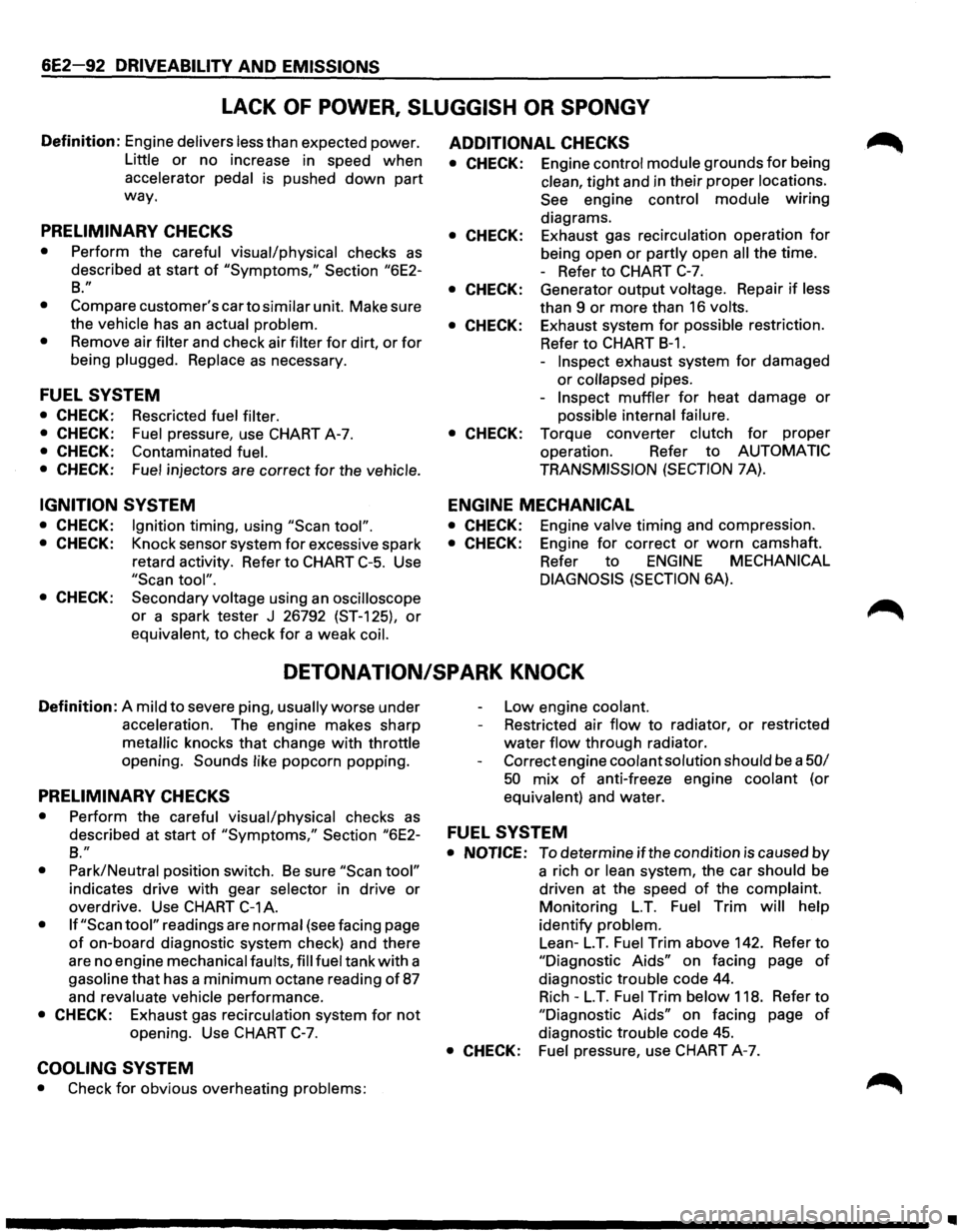
6E2-92 DRIVEABILITY AND EMISSIONS
LACK OF POWER, SLUGGISH OR SPONGY
Definition: Engine delivers less than expected power.
Little or no increase in speed when
accelerator
pedal is pushed down part
way.
PRELIMINARY CHECKS
• Perform the careful visual/physical checks as
described at start of "Symptoms," Section "6E2-
B."
•
Compare customer's car to similar unit. Make sure
the
vehicle has an actual problem.
• Remove air filter and check air filter for dirt, or for
being plugged. Replace as necessary.
FUEL SYSTEM
• CHECK: Rescricted fuel filter.
• CHECK: Fuel pressure, use CHART A-7.
• CHECK: Contaminated fuel.
• CHECK: Fuel injectors are correct for the vehicle.
IGNITION SYSTEM
• CHECK: Ignition timing, using "Scan tool".
• CHECK: Knock sensor system for excessive spark
retard activity. Refer to CHART
C-5. Use
"Scan tool".
• CHECK: Secondary voltage using an oscilloscope
or a spark tester J 26792 (ST-125), or
equivalent, to check for a weak coil.
ADDITIONAL CHECKS
• CHECK: Engine control module grounds for being
clean,
tight and in their proper locations.
See engine control module wiring
diagrams.
• CHECK: Exhaust gas recirculation operation for
being open or partly open all the time.
- Refer to CHART
C-7.
• CHECK: Generator output voltage. Repair if less
than 9
or more than 16 volts.
• CHECK: Exhaust system for possible restriction.
Refer
to CHART B-1.
-Inspect exhaust system for damaged
or collapsed pipes.
-
Inspect muffler for heat damage or
possible internal failure.
• CHECK: Torque converter clutch for proper
operation. Refer
to AUTOMATIC
TRANSMISSION
(SECTION 7A).
ENGINE MECHANICAL
• CHECK: Engine valve timing and compression.
• CHECK: Engine for correct or worn camshaft.
Refer
to ENGINE MECHANICAL
DIAGNOSIS
(SECTION 6A).
DETONATION/SPARK KNOCK
Definition: A mild to severe ping, usually worse under
acceleration. The engine makes sharp
metallic knocks that change with throttle
opening.
Sounds like popcorn popping.
PRELIMINARY CHECKS
• Perform the careful visual/physical checks as
Low engine coolant.
Restricted air
flow to radiator, or restricted
water flow through radiator.
Correct engine
coolant solution should be a 50/
50 mix of anti-freeze engine coolant (or
equivalent) and water.
described at start
of "Symptoms," Section "6E2-FUEL SYSTEM
B."
•
Park/Neutral position switch. Be sure "Scan tool"
indicates drive with gear selector in drive or
overdrive. Use
CHART C-1A.
• If "Scan tool" readings are normal (see facing page
of on-board diagnostic system check) and there
are no engine mechanical faults,
fill fuel tank with a
gasoline
that has a minimum octane reading of 87
and revaluate vehicle performance.
• CHECK: Exhaust gas recirculation system for not
opening. Use CHART C-7.
COOLING SYSTEM
• Check for obvious overheating problems:
• NOTICE: To determine if the condition is caused by
a rich
or lean system, the car should be
driven at the speed
of the complaint.
Monitoring
LT. Fuel Trim will help
identify problem.
Lean-
LT. Fuel Trim above 142. Refer to
"Diagnostic Aids" on facing page of
diagnostic trouble code 44.
Rich-LT. Fuel Trim below 118. Refer to
"Diagnostic Aids" on facing page of
diagnostic trouble code 45.
• CHECK: Fuel pressure, use CHART A-7.
..
Page 795 of 1928
DRIVEABILITV AND EMISSIONS 6E2-99
SECTION C
COMPONENTS SYSTEMS
CAUTION
When fasteners are removed, always reinstall them at the same location from which they were removed. If a
fastener needs
to be replaced, use the correct part number fastener for that application. If the correct part number
fastener is not available, a fastener of equal size and strength (or stronger) may be used. Fasteners that are not
reused, and those requiring thread locking compound will be called out. The correct torque value must be used
when installing fasteners that require it. If the above conditions are not followed, parts or system damage could
result.
Section
"C" provides information on the following:
• General description of components and sub-systems.
• On-vehicle service.
• Part names and group numbers.
• Diagnostic charts. These include a functional check of the system as well as diagnosis of any problem found in
the functional check.
For locations
of components, wiring diagrams, and engine control module terminal and view, refer to the front of
"Engine Components/Wiring Diagrams/Diagnostic Charts", Section "A".
Refer to the following sections for the appropriate sub-system information:
• C1 Engine Control Module (ECM) and Sensors ................................. Page 6E2-1 00
•
C2 Fuel Metering System .................................................. Page 6E2-116
• C3 Evaporative Emission (EVAP) Control System ............................... Page 6E2-134
• C4 Electronic Ignition (EI) System/Ignition Control (IC) ........................... Page 6E2-138
• C5 Knock Sensor (KS) System .............................................. Page 6E2-146
• C7 Exhaust Gas Recirculation (EGR) System ................................... Page 6E2-151
• C8 Shift Indicator Light (M/T Only) ........................................... Page 6E2-157
• C1 0 Air Conditioning (A/C) Compressor Clutch Control System ..................... Page 6E2-161
• C13 Positive Crankcase Ventilation (PCV) ....................................... Page 6E2-164
DIAGNOSTIC CHARTS
The following diagnostic charts can be found at the end of some of the sections.
• Chart C-1A Park/neutral Position (PNP) Switch Diagnosis (Auto Transmission only) .... Page 6E2-108
• Chart C-1 D Manifold Absolute Pressure (MAP) Output Check ...................... Page 6E2-11 0
•
Chart C-1 E Power Steering Pressure (PSP) Switch Diagnosis ...................... Page 6E2-112
• Chart C-1 F Heated Oxygen Sensor (H02S) Heater Check ......................... Page 6E2-114
• Chart C-2A Injector Balance Test ............................................. Page 6E2-128
• Chart C-2C Idle Air Control (lAC) System Check ................................. Page 6E2-130
• Chart C-2D Induction Air Control System Check (DOHC Only) ...................... Page 6E2-132
• Chart C-3 Evaporate Emission Canister Purge Valve Check ....................... Page 6E2-136
• Chart C-4D-1 Electronic Ignition (EI) Misfire at Idle ................................ Page 6E2-142
• Chart C-4D-2 Electronic Ignition (EI) Misfire Under Load ............................ Page 6E2-144
• Chart C-5 Knock Sensor (KS) System Check .................................. Page 6E2-148
• Chart C-7A Exhaust Gas Recirculation (EGR) System Check ....................... Page 6E2-154
• Chart C-8 Manual Transmission (MIT) Shift Light Check ......................... Page 6E2-158
• Chart C-1 0 Air Conditioning (A/C) System Functional Check ....................... Page 6E2-162
Page 802 of 1928
6E2-1 06 DRIVEABILITV AND EMISSIONS
1••1 REMOVAL
\f7 CAUTION:
Y/ Care must be taken when handling Engine
Coolant Temperature (ECT) sensor. Damage to
ECT sensor will affect proper operation of the fuel
injection system.
Preparation: • Negative battery cable.
•
Drain engine coolant system.
1. Inlet manifold assembly
• Refer to "Fuel metering system" section "6E2-
C2"
for removal procedure.
2. Electrical connector
3. ECT sensor
• Remove from rear of engine coolant transfer
tube.
I••IINSTALLATION
3. ECT sensor
• Apply sealer or equivalent to threads only.
•
Tighten the ECT sensor to the specified torque
~~~ Torque N·m (lb·ft) I 30 (22)
2. ECT sensor connector
1. Intake manifold assembly
• Refer to "Fuel metering system" section "6E2-
C2" for installation.
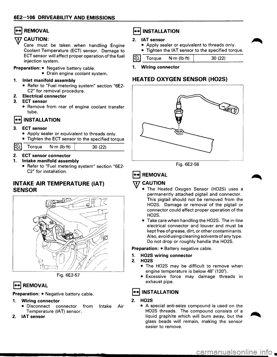
INTAKE AIR TEMPERATURE (IAT)
SENSOR
Fig. 6E2-57
1••1 REMOVAL
Preparation: • Negative battery cable.
1. Wiring connector
• Disconnect connector from Intake Air
Temperature (IAT) sensor.
2. IAT sensor
I••IINSTALLATION
2. IAT sensor
• Apply sealer or equivalent to threads only.
•
Tighten the IAT sensor to the specified torque.
~~~ Torque N·m (lb·ft) 30 (22)
1. Wiring
connector
HEATED OXYGEN SENSOR (H02S)
Fig. 6E2-58
1••1 REMOVAL
'fCAUTION
• The Heated Oxygen Sensor (H02S) uses a
permanently attached pigtail and connector.
This
pigtail should not be removed from the
H02S. Damage or removal of the pigtail or
connector
could affect proper operation of the
H02S.
•
Take care when handling the H02S. The in-line
electrical
connector and louver end must be
kept free
of grease, dirt, or other contaminants.
Also, avoid using cleaning solvents of any type.
Do not drop or roughly handle the H02S.
Preparation: • Battery negative cable.
1. H02S wiring connector
2. H02S
• The H02S may be difficult to remove when
engine temperature is
below 48• (120.).
•
Excessive force may damage threads in
exhaust pipe.
I••IINSTALLATION
2. H02S
• A special anti-seize compound is used on the
H02S threads. The compound consists of a
liquid graphite which will burn away, but the
glass beads will remain, making the sensor
easier
to remove.
•