ISUZU TROOPER 1995 Workshop Manual
Manufacturer: ISUZU, Model Year: 1995, Model line: TROOPER, Model: ISUZU TROOPER 1995Pages: 1928
Page 241 of 1928
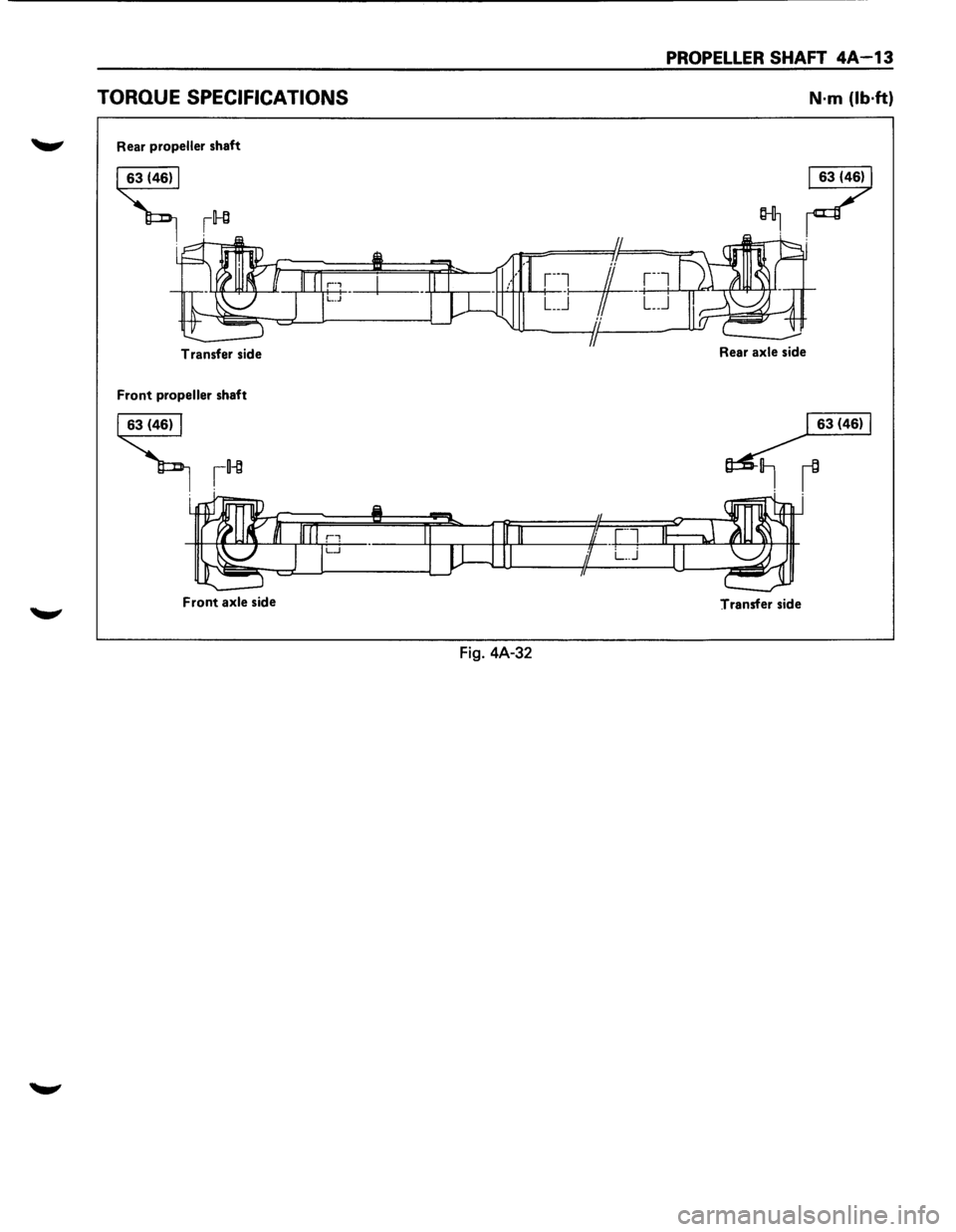
PROPELLER SHAFT 4A-13
TORQUE SPECIFICATIONS N·m (lb·ft)
....._., Rear propeller shaft
Transfer side
Front propeller shaft
~
Front axle side
Transfer side
Fig. 4A-32
Page 242 of 1928
MEMO
Page 243 of 1928
REAR AXLE 48-1
SECTION 48
REAR AXLE
\V CAUTION:
When fasteners are removed, always reinstall them at the same location from which they were removed.
If a fastener needs to be replaced, use the correct part number fastener for that application. If the correct
part number fastener is not available, a fastener of equal size and strength (or stronger) may be used.
Fasteners
that are not reused, and those requiring thread locking compound, will be called out. The
correct
torque values must be used when installing fasteners that require torque. If the above conditions
are not followed, parts or system damage could result.
CONTENTS
General Description . . . . . . . . . . . . . . . . . . . . 48-1
Diagnosis of Rear
Axle Noise . .
. . . . . . . . . . 48-3
On-Vehicle Service ..................... 48-4
Axle Housing . .
. . . . . . . . . . . . . . . . . . . . . 48-4
Axle Shaft . .
. . . . . . . . . . . . . . . . . . . . . . . . 48-7
Pinion
Oil Seal . .
. . . . . . . . . . . . . . . . . . . .
48-10
Differential Assembly
. .
. . . . . . . . . . . . . . 48-11 Unit
Repair . . . . . . . . . . . . . . . . . . . . . . . . . . . 48-13
Differential Assembly . .
. . . . . . . . . . . . . .
48-13 Differential Cage Assembly . . . . . . . . . . . . 48-23
Limited
Slip Differential . .
. . . . . . . . . . . . 48-27
Main Data and Specifications . . . . . . . . . . . . 48-33
General Specifications . .
. . . . . . . . . . . . . . 48-33
Torque Specifications
................ 48-34
Special Tools ......................... 48-35
GENERAL DESCRIPTION
The rear axle assembly is of the semi-floating type in
which the vehicle weight is carried on the axle
housing (Fig. 48-1).
The center
line of the pinion gear is below the center
line of the ring gear (hypoid drive).
All parts necessary to transmit power from the
propeller shaft to the rear wheels are enclosed in a
banjo type axle housing.
The 8.7 inch ring gear rear axle uses a conventional
ring and
pinion gear set to transmit the driving force
of the engine to the rear wheels. This gear set transfers
this driving force at a 90 degree angle from the
propeller shaft to the drive shafts. The
axle shafts
are supported at the wheel end of the
shaft by a roller bearing.
The
pinion gear is supported by two tapered roller
bearings. The pinion depth is set by a shim pack
located between the gear end of the pinion and the
roller bearing that is pressed onto the pinion. The
pinion bearing preload is set by crushing a collapsible
spacer between the bearings in the axle housing.
Page 244 of 1928
48-2 REAR AXLE
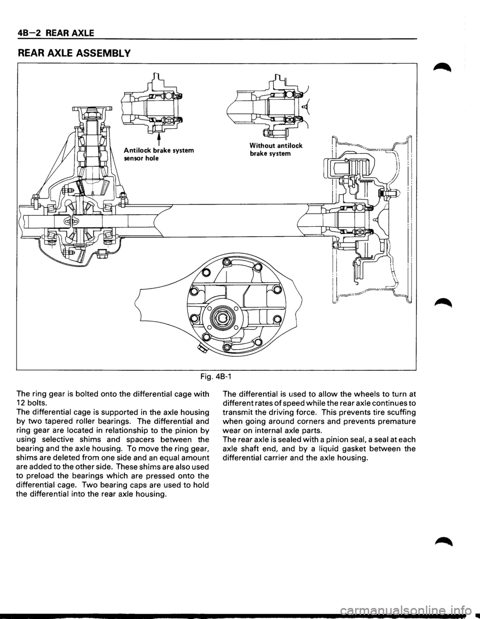
REAR AXLE ASSEMBL V
Antilock brake system
sensor
hole
Without antilock
brake system
Fig. 48-1
The ring gear
is bolted onto the differential cage with
12 bolts.
The differential cage is supported in the axle housing
by two tapered roller bearings. The differential and
ring gear are
located in relationship to the pinion by
using selective shims and spacers between the
bearing and the
axle housing. To move the ring gear,
shims are deleted from one side and an equal amount
are added to the other side. These shims are also used
to preload the bearings which are pressed onto the
differential cage. Two bearing caps are used to hold
the differential into the rear axle housing. The
differential is
used to allow the wheels to turn at
different rates
of speed while the rear axle continues to
transmit the driving force. This prevents tire scuffing
when going around corners and prevents premature
wear on internal axle parts.
The rear
axle is sealed with a pinion seal, a seal at each
axle shaft end, and by a liquid gasket between the
differential carrier and the axle housing.
II
Page 245 of 1928
REAR AXLE 48-3
DIAGNOSIS OF REAR AXLE NOISE
Many noises that seem to come from the rear axle
actually
originate from other sources such as tires,
road surface, wheel bearings, engine, transmission,
muffler,
or body drumming. Investigate to find the
source
ofthe noise before disassembling the rear axle.
Rear axles,
like any other mechanical device, are not
absolutely quiet but should be considered quiet unless
some abnormal noise is present.
To make a systematic check
for axle noise, observe the
following:
1. Select a level asphalt road to reduce tire noise and
body drumming.
2. Check rear axle lubricant level to assure correct
level, and then drive the vehicle far enough to
thoroughly warm up the rear axle lubricant.
3. Note the speed at which noise occurs. Stop the
vehicle and put the transmission in neutral. Run
the engine speed
slowly up and down to
determine if the noise is caused by exhaust,
muffler noise, or other engine conditions.
4. Tire noise changes with different road surfaces;
axle noises do not. Temporarily inflate all tires to
344
kPa (50 psi) (for test purposes only). This will
change noise caused by tires but will not affect
noise caused by the rear
axle.
Rear axle nose usually stops when coasting at
speeds under
48 km/h (30 mph); however, tire
noise continues
with a lower tone. Rear axle noise
usually changes when comparing pull and coast,
but tire noise stays about the same.
Distinguish between tire noise and rear
axle noise
by noting
if the noise changes with various
speeds
or sudden acceleration and deceleration.
Exhaust and
axle noise vary under these
conditions,
while tire noise remains constant and
is more pronounced at speeds
of 32 to 48 km/h
(20 to 30 mph). Further check for tire noise by
driving the vehicle
over smooth pavements or dirt
roads (not gravel) with the tires at normal
pressure.
If the noise is caused by tires, it will
change noticeably with changes in road surface.
5. Loose or rough front wheel bearings will cause
noise
which may be confused with rear axle
noise; however, front wheel bearing noise does
not change when comparing drive and coast.
Light application
of the brake while holding
vehicle speed steady
will often cause wheel
bearing noise to diminish. Front wheel bearings
may be checked for noise by jacking up the
wheels and spinning them
or by shaking the
wheels
to determine if bearings are loose.
6. Rear suspension rubber bushings and spring
insulators dampen
out rear axle noise when
correctly installed. Check to see that there is no
link or rod loosened or metal-to-metal contact.
7. Make sure that there is no metal-to-metal contact
between the
floor and the frame.
After the noise has been determined to be in the axle,
the type of axle noise should be determined, in order to
make any necessary repairs.
GEAR NOISE
Gear noise (whine) is audible from 32 to 89 km/h (20 to
55 mph) under four driving conditions.
1. In drive under acceleration or heavy pull.
2. Driving under load or under constant speed.
3. When using enough throttle to keep the vehicle
from driving the engine while the vehicle slows
down gradually (engine still pulls slightly).
4. When coasting with the vehicle in gear and the
throttle closed. The gear noise is
usually more
noticeable between 48 and 64
km/h (30 and 40
mph) and 80 and 89 km/h (50 and 55 mph).
BEARING NOISE
Bad bearings generally produce a rough growl or
grating sound, rather than the whine typical of gear
noise. Bearing noise frequently
"wow-wows" at
bearing rpm, indicating a bad pinion
or rear axle side
bearing. This noise can
be confused with rear wheel
bearing noise.
REAR WHEEL BEARING NOISE
Rear wheel bearing noise continues to be heard while
coasting at low speed with transmission in the neutral.
Noise may diminish by gentle braking. Jack up the rear
wheels, spin them by hand and
listen for noise at the
hubs. Replace any faulty
wheel bearings.
KNOCK AT LOW SPEEDS
Low speed knock can be caused by worn universal
joints or a side gear hub counter bore in the cage that is
worn oversize. Inspect and replace universal joints or
cage and side gears as required.
BACKLASH CLUNK
Excessive clunk on acceleration and deceleration can
be caused by a worn rear axle pinion shaft, a worn
cage, excessive clearance between the axle and the
side gear splines, excessive clearance between the
side gear hub and the counterbore in the cage,
worn
pinion and side gear teeth, worn thrust washers, or
excessive drive pinion and ring gear backlash.
Remove
worn parts and replace as required. Select
close-fitting parts when possible. Adjust pinion and
ring gear backlash.
Page 246 of 1928
48-4 REAR AXLE
ON-VEHICLE SERVICE
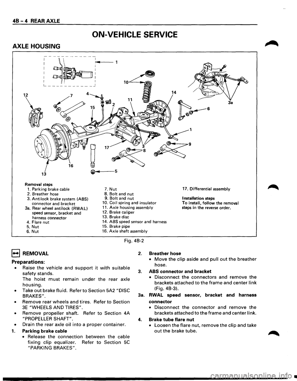
AXLE HOUSING
; ~~:r~4 ,
L ___________ j
12 14
3a
1
• 3
~
~·
13 5
Removal steps
1. Parking brake cable 7. Nut 17.
Differential assembly
2. Breather hose 8.
Bolt and nut 9. Bolt and nut Installation steps
3. Anti lock brake system (ABS)
connector and bracket 10. Coil spring and insulator To install, follow the removal
steps in the reverse order.
3a. Rear wheel antilock (RWAL)
speed sensor, bracket and
harness connector 11.
Axle housing assembly
12. Brake caliper
13. Brake disc
4. Flare
nut 14. ABS speed sensor and harness
5. Nut 15.
Brake pipe
6. Nut 16.
Axle shaft assembly
Fig. 4B-2
1••1 REMOVAL
Preparations:
• Raise the vehicle and support it with suitable
safety stands.
The
hoist must remain under the rear axle
housing.
• Take out brake fluid. Refer to Section 5A2 "DISC
BRAKES".
•
Remove rear wheels and tires. Refer to Section
3E "WHEELS AND TIRES".
•
Remove propeller shaft. Refer to Section 4A
"PROPELLER SHAFT".
•
Drain the rear axle oil into a proper container.
1. Parking brake cable
•
Release the connection between the cable
fixing clip equalizer. Refer to Section 5C
"PARKING BRAKES".
2. Breather hose
• Move the clip aside and pull out the breather
hose.
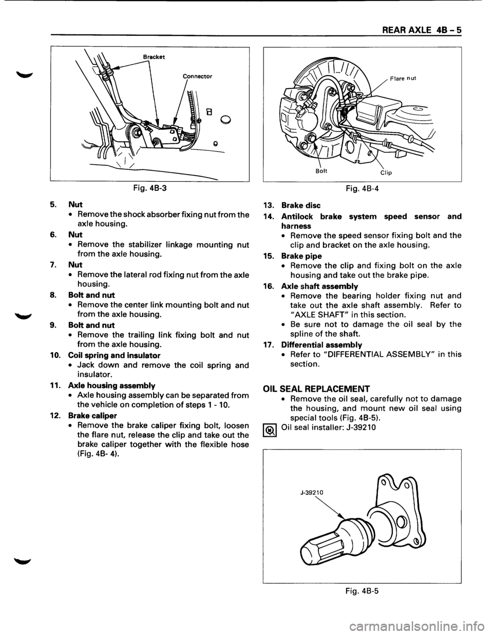
3. ABS connector and bracket
• Disconnect the connectors and remove the
brackets attached to the frame and center link
(Fig. 4B-3).
3a. RWAL speed sensor,
bracket and harness
connector
• Disconnect the connector and remove the
brackets attached to the frame and center link.
4. Brake tube flare nut
• Loosen the flare nut, remove the clip and take
out the brake tube.
•
Page 247 of 1928
5.
6.
7.
8.
........,
9.
10.
11.
12.
B 0
g
Fig. 48-3
Nut
• Remove the shock absorber fixing nut from the
axle housing.
Nut
• Remove the stabilizer linkage mounting nut
from the axle housing.
Nut
• Remove the lateral rod fixing nut from the axle
housing.
Bolt and nut
• Remove the center link mounting bolt and nut
from the axle housing .
Bolt and nut
• Remove the trailing link fixing bolt and nut
from the axle housing.
Coil spring and insulator
• Jack down and remove the coil spring and
insulator.
Axle housing assembly
• Axle
housing assembly can be separated from
the vehicle on completion of steps 1 -10.
Brake caliper
•
Remove the brake caliper fixing bolt, loosen
the
flare nut, release the clip and take out the
brake caliper
together with the flexible hose
(Fig. 48-
4).
REAR AXLE 48 - 5
Bolt Clip
Fig. 48-4
13. Brake disc
14.
Antilock brake system speed sensor and
harness
• Remove the speed sensor fixing bolt and the
clip and bracket on the axle housing.
15. Brake
pipe
• Remove the clip and fixing bolt on the axle
housing and take out the brake pipe.
16.
Axle shaft assembly
• Remove the bearing holder fixing nut and
take
out the axle shaft assembly. Refer to
"AXLE SHAFT" in this section.
• Be sure not to damage the oil seal by the
spline of the shaft.
17. Differential
assembly
• Refer to "DIFFERENTIAL ASSEMBLY" in this
section.
OIL SEAL REPLACEMENT
• Remove the oil seal, carefully not to damage
the housing, and mount new oil seal using
special tools (Fig. 48-5).
1®.1 Oil seal installer: J-39210
Fig. 48-5
Page 248 of 1928
48-6 REAR AXLE
1••1 INSTALLATION
17. Differential assembly
• Refer to "DIFFERENTIAL ASSEMBLY" in this
section.
16.
Axle shaft assembly
• Tighten the bearing holder mounting nut to the
specified torque.
~~~ Torque N·m (lb·ft) 74 (54)
• Be sure not to damage the oil seal by the spline
of the shaft.
15. Brake
pipe
14. Antilock brake system (ABS) speed sensor and
harness
• Refer to Section 5A4 "4-WHEEL ANTI-LOCK
BRAKE SYSTEM (ABS)".
13. Brake disc
12. Brake
caliper
• Refer to Section 5A2 "DISC BRAKES".
11.
Axle housing assembly
10. Coil spring and insulator
9. Bolt and nut
• For the procedures in Items 9-5, refer to Section
3D "REAR SUSPENSION".
8. Bolt and nut
7. Nut
6. Nut
5. Nut
4. Brake tube flare nut
• Refer to Section 5A2 "DISC BRAKES".
3a. Rear Wheel Antilock (RWAL) speed sensor,
bracket and harness connector
• Tighten the speed sensor bolt to the specified
torque.
1~1 Torque N-m (lb·ft) j 24 (18)
3. ABS connector and bracket
2. Breather hose
1. Parking brake cable
• Refer to Section 5C "PARKING BRAKES".
Page 249 of 1928
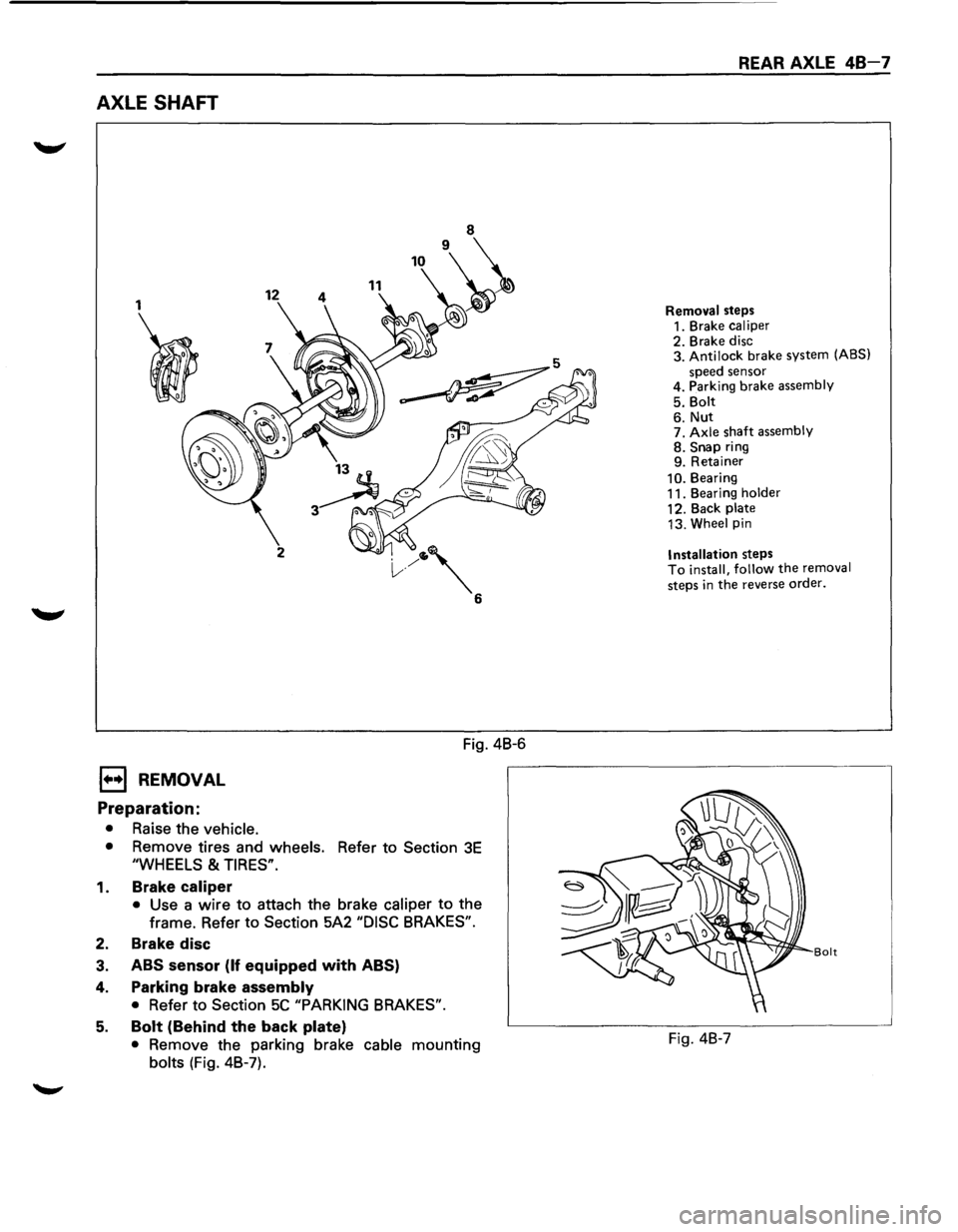
AXLE SHAFT
1
I
1••1 REMOVAL
Preparation:
• Raise the vehicle.
12 11
2
Fig. 4B-6
• Remove tires and wheels. Refer to Section 3E
"WHEELS & TIRES".
1. Brake caliper
• Use a wire to attach the brake caliper to the
frame. Refer to
Section 5A2 "DISC BRAKES".
2. Brake disc
3. ABS sensor (If equipped with ABS)
4. Parking brake assembly
• Refer to Section 5C "PARKING BRAKES".
5. Bolt (Behind the back plate)
• Remove the parking brake cable mounting
bolts (Fig. 4B-7).
REAR AXLE 48-7
Removal steps
1. Brake caliper
2. Brake disc
3. Antilock brake system (ABS)
speed sensor
4. Parking brake assembly
5. Bolt
6. Nut 7. Axle shaft assembly 8. Snap ring
9. Retainer
10. Bearing
11. Bearing holder
12. Back plate
13. Wheel pin
Installation steps To install, follow the removal
steps
in the reverse order.
Bolt
Fig. 4B-7
Page 250 of 1928
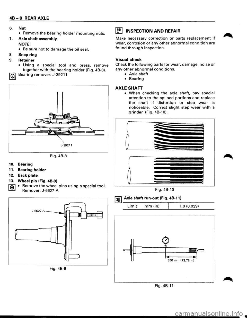
48 - 8 REAR AXLE
6. Nut
• Remove the bearing holder mounting nuts.
7. Axle shaft assembly
NOTE:
• Be sure not to damage the oil seal.
8. Snap ring
9. Retainer
• Using a special tool and press, remove
together with the bearing holder (Fig. 4B-8).
1 ®I Bearing remover: J-39211
J-39211
Fig. 4B-8
10. Bearing
11. Bearing
holder
12. Back plate
13. Wheel pin (Fig. 4B-9)
1®.1 • Remove the wheel pins using a special tool.
Remover: J-6627-A
J-6627-A
Fig. 4B-9
I L•l INSPECTION AND REPAIR
Make necessary correction or parts replacement if
wear, corrosion or any other abnormal condition are
found through inspection.
Visual check
Check the following parts for wear, damage, noise or
any other abnormal conditions.
• Axle shaft
• Bearing
AXLE SHAFT
• When checking the axle shaft, pay special
attention to the splined portions and replace
the shaft if distortion or step wear is
noticeable. Correct slight step wear with a
grinder (Fig. 4B-10).
Fig. 4B-10
~~~ Axle shaft run-out (Fig. 4B-11)
Limit mm(in) 1.0 (0.039)
350 mm (13.78 in)
Fig. 4B-11
•