lock ISUZU TROOPER 1995 Workshop Manual
[x] Cancel search | Manufacturer: ISUZU, Model Year: 1995, Model line: TROOPER, Model: ISUZU TROOPER 1995Pages: 1928
Page 489 of 1928
ILLUSTRATION
'~ ~··
J -
~
. .
"
~
"f'38~
0
~~ '~
--~ S::S.·f
-~; -~b'
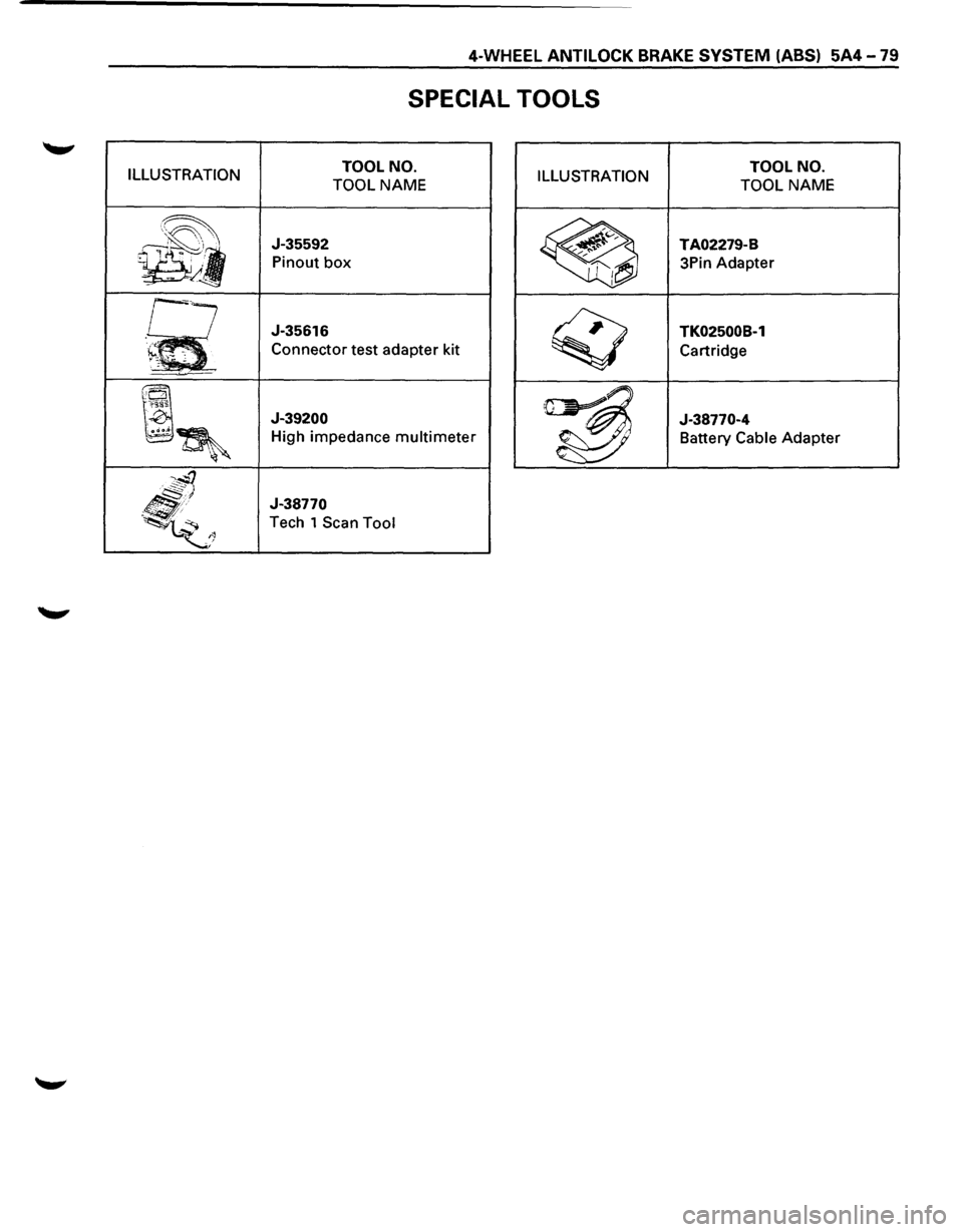
SPECIAL TOOLS
TOOL NO.
TOOL
NAME ILLUSTRATION
J-35592
Pinout box
J-35616
Connector test adapter kit
J-39200
High impedance multimeter
J-38770
Tech 1 Scan Tool
TOOL NO.
TOOL
NAME
TA02279-B
3Pin Adapter
TK02500B-1
Cartridge
J-38770-4 Battery
Cable Adapter
Page 491 of 1928
PARKING BRAKES 5C-1
SECTION 5C
PARKING BRAKES
'\f7 CAUTION:
Yf All brake attaching fasteners are an important attaching part in that they could affect performance of vital
parts and systems, and/or could result in major repair expense. They must be replaced with one ofthe same
part number
or with and equivalent part if replacement becomes necessary. Do not use replacement parts of
lesser quality or substitute design. Torque values must be used as specified during reassembly to assure
proper retention
of these parts.
CONTENTS
General Description ..................... 5C-1
Operation . . . . . . . . . . . . . . . . . . . . . . . . . . . . . 5C-2
On-Vehicle Service
..................... 5C-3
Parking Brake Lever Replacement . .
. . . . .
5C-3
Parking Brake Front Cable . .
. . . . . . . . . . .
5C-4
Parking Brake Rear Cable . .
. . . . . . . . . . . .
5C-5
Parking Brake Lining Inspection ......... 5C-6
Parking Brake Rotor (Drum) Inspection ... 5C-6
Parking Brake Adjustment .............. 5C-7
Main Data and Specifications ............. 5C-8
General
Specifications ................. 5C-8
Torque Specifications ................. 5C-8
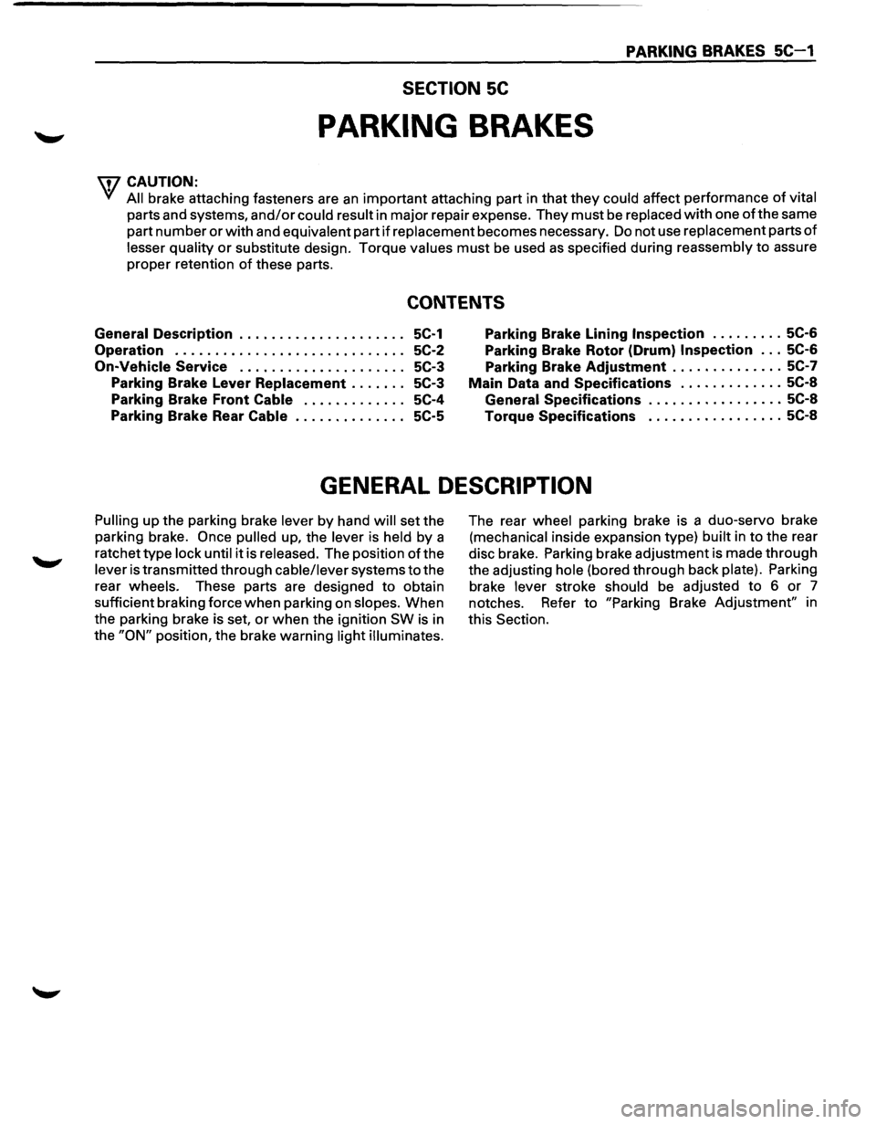
GENERAL DESCRIPTION
Pulling up the parking brake lever by hand will set the
parking brake.
Once pulled up, the lever is held by a
ratchet type
lock until it is released. The position of the
lever is transmitted through cable/lever systems to the
rear
wheels. These parts are designed to obtain
sufficient braking force
when parking on slopes. When
the parking brake is set,
or when the ignition SW is in
the
"ON" position, the brake warning light illuminates.
The rear wheel parking brake is a duo-servo brake
(mechanical inside expansion type) built in to the rear
disc brake. Parking brake adjustment is made through
the adjusting
hole (bored through back plate). Parking
brake
lever stroke should be adjusted to 6 or 7
notches. Refer
to "Parking Brake Adjustment" in
this Section.
Page 497 of 1928
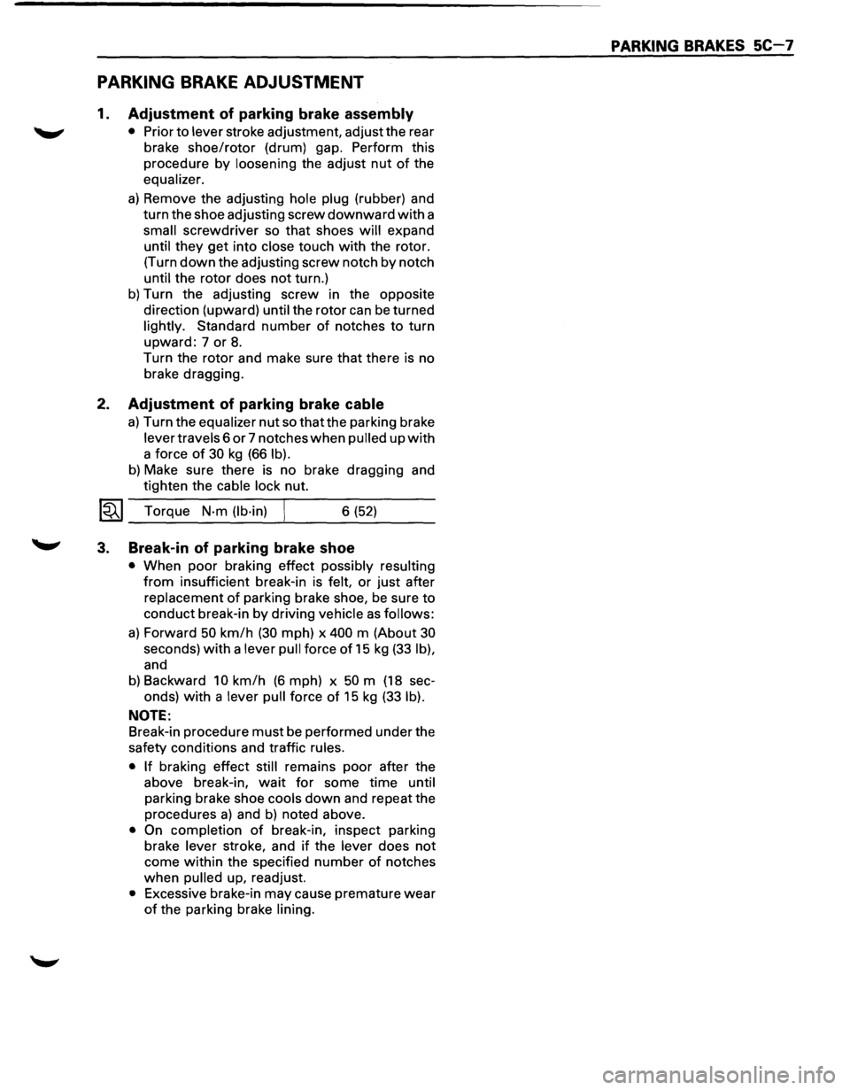
PARKING BRAKE ADJUSTMENT
1. Adjustment of parking brake assembly
• Prior to lever stroke adjustment, adjust the rear
brake
shoe/rotor (drum) gap. Perform this
procedure
by loosening the adjust nut of the
equalizer.
a) Remove the adjusting hole plug (rubber) and
turn the shoe adjusting screw
downward with a
small screwdriver so that shoes will expand
until
they get into close touch with the rotor.
(Turn
down the adjusting screw notch by notch
until the rotor does not turn.)
b) Turn the adjusting screw in the opposite
direction (upward) until the rotor can
be turned
lightly. Standard
number of notches to turn
upward: 7 or 8.
Turn the rotor and make sure that there is no
brake dragging.
2. Adjustment of parking brake cable
a) Turn the equalizer nut so that the parking brake
lever travels 6
or 7 notches when pulled up with
a force of 30 kg (66 lb).
b) Make sure there is no brake dragging and
tighten the cable lock nut.
l~l Torque N·m (lb·in) 6 (52)
3. Break-in of parking brake shoe
• When poor braking effect possibly resulting
from insufficient break-in is felt, or just after
replacement
of parking brake shoe, be sure to
conduct break-in by driving vehicle as follows:
a) Forward 50 km/h (30 mph) x 400 m (About 30
seconds) with a lever pull force of 15 kg (33 lb),
and
b) Backward 10 km/h (6 mph) x 50 m (18 sec-
onds)
with a lever pull force of 15 kg (33 lb).
NOTE:
Break-in procedure must be performed under the
safety conditions and traffic rules.
• If braking effect still remains poor after the
above break-in,
wait for some time until
parking brake shoe cools
down and repeat the
procedures
a) and b) noted above.
• On completion of break-in, inspect parking
brake lever stroke, and
if the lever does not
come within the specified number of notches
when pulled up, readjust.
• Excessive brake-in may cause premature wear
of the parking brake lining.
PARKING BRAKES SC-7
Page 499 of 1928
ENGINE DIAGNOSIS S-1
ENGINE
CONTENTS
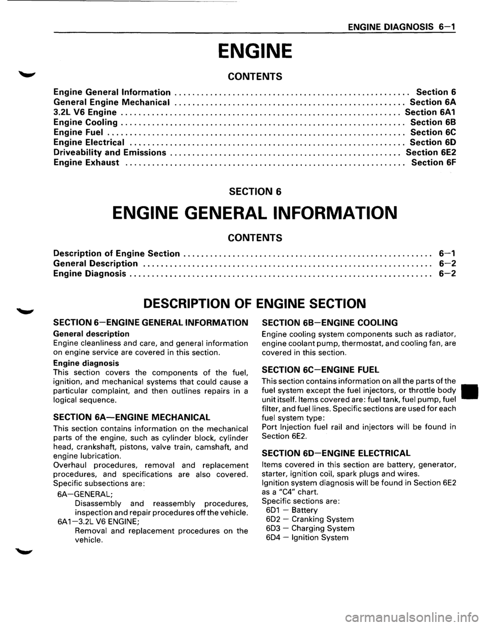
Engine General Information . . . . . . . . . . . . . . . . . . . . . . . . . . . . . . . . . . . . . . . . . . . . . . . . . . . . . Section S
General
Engine Mechanical .................................................... Section SA
3.2L VS Engine ............................................................... Section SA1
Engine Cooling . . . . . . . . . . . . . . . . . . . . . . . . . . . . . . . . . . . . . . . . . . . . . . . . . . . . . . . . . . . . . . . . Section S8
Engine Fuel . . . . . . . . . . . . . . . . . . . . . . . . . . . . . . . . . . . . . . . . . . . . . . . . . . . . . . . . . . . . . . . . . . . Section SC
Engine Electrical . . . . . . . . . . . . . . . . . . . . . . . . . . . . . . . . . . . . . . . . . . . . . . . . . . . . . . . . . . . . . . Section SD
Driveability and Emissions . . . . . . . . . . . . . . . . . . . . . . . . . . . . . . . . . . . . . . . . . . . . . . . . . . . . Section SE2
Engine Exhaust . . . . . . . . . . . . . . . . . . . . . . . . . . . . . . . . . . . . . . . . . . . . . . . . . . . . . . . . . . . . . . . Section SF
SECTION 6
ENGINE GENERAL INFORMATION
CONTENTS
Description of Engine Section . . . . . . . . . . . . . . . . . . . . . . . . . . . . . . . . . . . . . . . . . . . . . . . . . . . . . . . . S-1
General Description . . . . . . . . . . . . . . . . . . . . . . . . . . . . . . . . . . . . . . . . . . . . . . . . . . . . . . . . . . . . . . . . . S-2
Engine Diagnosis . . . . . . . . . . . . . . . . . . . . . . . . . . . . . . . . . . . . . . . . . . . . . . . . . . . . . . . . . . . . . . . . . . . . S-2
DESCRIPTION OF ENGINE SECTION
SECTIONS-ENGINE GENERAL INFORMATION SECTION S8-ENGINE COOLING
General description
Engine cleanliness and care, and general information
on engine service are covered in this section.
Engine diagnosis
This section covers the components of the fuel,
ignition, and mechanical systems that could cause a
particular complaint, and then outlines repairs in a
logical sequence.
SECTION SA-ENGINE MECHANICAL
This section contains information on the mechanical
parts of the engine, such as cylinder block, cylinder
head, crankshaft, pistons, valve train, camshaft, and
engine
lubrication.
Overhaul
procedures, removal and replacement
procedures, and specifications are also covered.
Specific subsections are:
SA-GENERAL;
Disassembly and reassembly procedures,
inspection and repair procedures
off the vehicle.
6A 1-3.2L V6 ENGINE;
Removal
and replacement procedures on the
vehicle.
Engine cooling system components such as radiator,
engine
coolant pump, thermostat, and cooling fan, are
covered
in this section.
SECTION SC-ENGINE FUEL
This section contains information on all the parts of the
fuel system except the fuel injectors, or throttle body II
unit itself. Items covered are: fuel tank, fuel pump, fuel
filter,
and fuel lines. Specific sections are used for each
fuel system type:
Port
Injection fuel rail and injectors will be found in
Section
6E2.
SECTION SD-ENGINE ELECTRICAL
Items covered in this section are battery, generator,
starter, ignition
coil, spark plugs and wires.
Ignition system diagnosis will be found in Section 6E2
as a "C4" chart.
Specific sections are:
601 -Battery
602 - Cranking System
603 -Charging System
604 -Ignition System
Page 517 of 1928
GENERAL ENGINE MECHANICAL 6A-1
SECTION 6A
GENERAL ENGINE MECHANICAL
CONTENTS
Cylinder Head . . . . . . . . . . . . . . . . . . . . . . . . 6A-1
Valve Springs,
Oil Controller, Valve,
Valve Guide, (and HLA for
DOHC) . .
. . .
6A-4
Camshaft . .
. . . . . . . . . . . . . . . . . . . . . . . . . . GA-11
Rocker Arm Assembly . . . . . . . . . . . . . . . . .
GA-17
Oil Pump ............................ GA-20
Crankshaft ........................... GA-23
Piston and Connecting Rod ............. GA-30
Cylinder Block ........................ GA-37
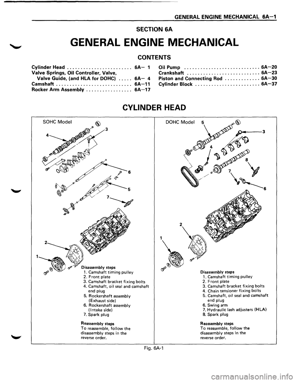
CYLINDER HEAD
SOHC Model
2
Disassembly steps
1. Camshaft timing pulley 2. Front plate
3. Camshaft bracket fixing bolts 4. Camshaft, oil seal and camshaft end plug
5. Rockershaft assembly (Exhaust side)
6. Rockershaft assembly (Intake side) 7. Spark plug
Reassembly steps
To reassemble, follow the disassembly steps in the reverse order.
DOHC Model
2
1
~
Fig. 6A-1
Disassembly steps
1. Camshaft timing pulley 2. Front plate 3. Camshaft bracket fixing bolts 4. Chain tensioner fixing bolts
5. Camshaft, oil seal and camshaft end plug
6. Swing arm 7. Hydraulic lash adjusters (HLA)
8.
Spark plug
Reassembly steps To reassemble, follow the disassembly steps in the reverse order.
Page 525 of 1928
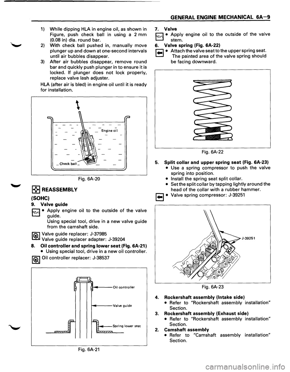
1) While dipping HLA in engine oil, as shown in
Figure, push check
ball in using a 2 mm
(0.08 in) dia. round bar.
2) With check ball pushed in, manually move
plunger up and down at one-second intervals
until
air bubbles disappear.
3) After air bubbles disappear, remove round
bar and
quickly push plunger in to ensure it is
locked. If plunger does not lock properly,
replace valve lash adjuster.
HLA (after air is
bled) in engine oil until it is ready
for installation.
-_ Engine oil
_Check ball_
Fig. 6A-20
l•!•l REASSEMBL V
(SOHC)
9. Valve guide
C1 • Apply engine oil to the outside of the valve
t..::::.l guide.
Using
special tool, drive in a new valve guide
from the camshaft side.
li5\l Valve guide replacer: J-37985
~ Valve guide replacer adapter: J-39204
8. Oil controller and spring lower seat (fig. 6A·21)
• Using special tool, drive in a new oil controller.
1®.1 Oil controller replacer: J-38537
~---Valve guide
Fig. 6A-21
GENERAL ENGINE MECHANICAL 6A-9
7. Valve
C1 • Apply engine oil to the outside of the valve
t..::::.l stem.
6. Valve spring (fig. 6A-22)
r=l • Attach the valve seatto the upper spring seat.
1.=.1 The painted area of the valve spring should
be facing downward.
Fig. 6A-22
5. Split collar and upper spring seat (Fig. 6A-23)
• Use a spring compressor to push the valve
spring into position.
• Install the spring seat split collar.
• Set
the split collar by tapping lightly around the
head
of the collar with a rubber hammer.
, ... ,. Valve spring compressor: J-39251
J·39251
Fig. 6A-23
4. Rockershaft assembly (Intake side)
• Refer to "Rockershaft assembly installation"
Section.
3. Rockershaft assembly (Exhaust side)
• Refer to "Rockershaft assembly installation"
Section.
2. Camshaft assembly
• Refer to "Camshaft assembly installation"
Section.
Page 527 of 1928
GENERAL ENGINE MECHANICAL 6A-11
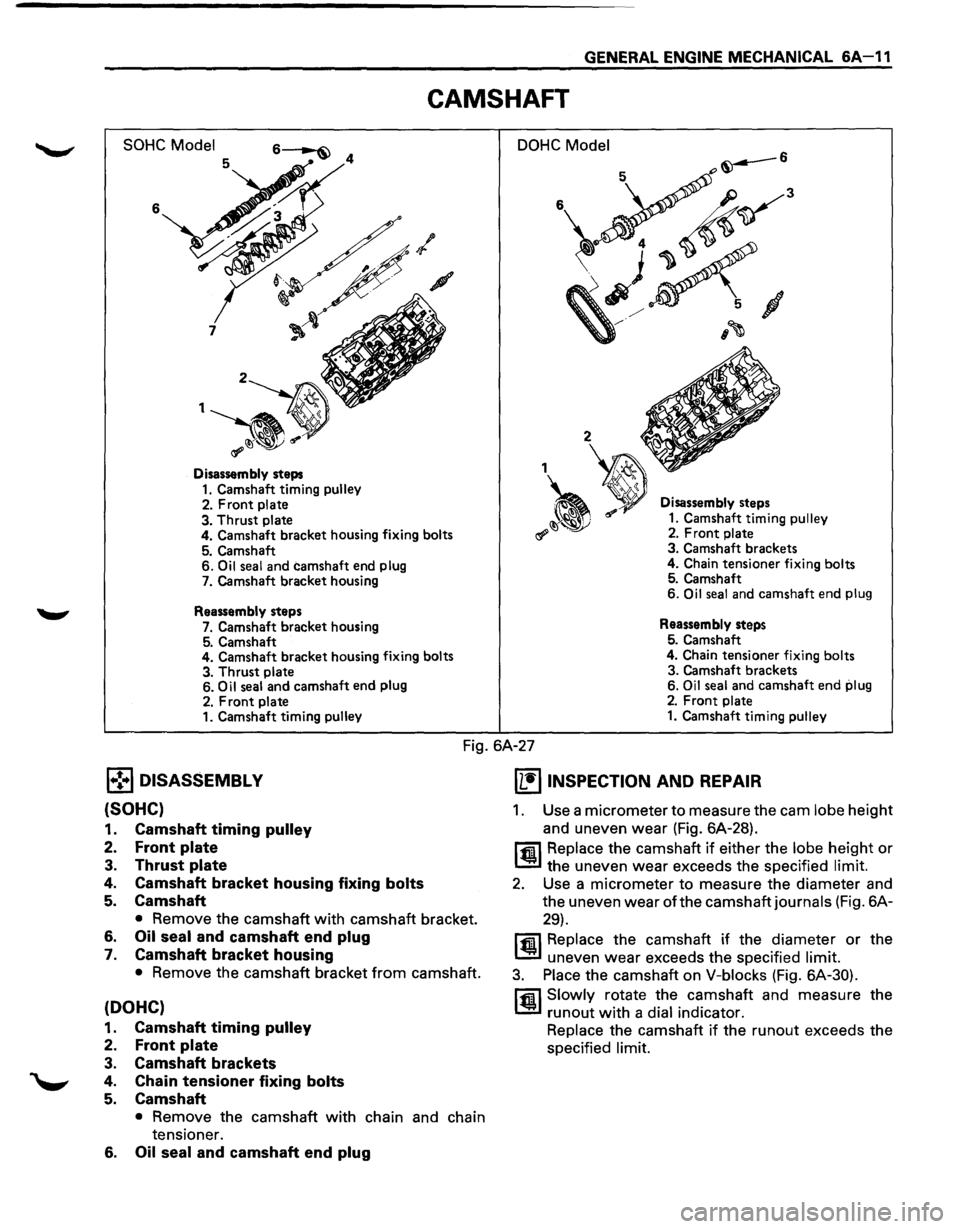
CAMSHAFT
SOHC Model
6 7
1
Disassembly steps
1. Camshaft timing pulley
2. Front plate
3. Thrust plate 4. Camshaft bracket housing fixing bolts
5. Camshaft 6. Oil seal and camshaft end plug
7. Camshaft bracket housing
Reassembly steps
7. Camshaft bracket housing 5. Camshaft
4. Camshaft bracket housing fixing bolts
3.
Thrust plate
6. Oil seal and camshaft end plug
2. Front plate 1. Camshaft timing pulley
DOHC Model
Disassembly steps
1. Camshaft timing pulley 2. Front plate
3. Camshaft brackets
4. Chain tensioner fixing bolts
5. Camshaft
6. Oil seal and camshaft end plug
Reassembly steps
5. Camshaft
4. Chain tensioner fixing bolts
3. Camshaft brackets
6.
Oil seal and camshaft end plug 2. Front plate
1. Camshaft timing pulley
Fig. 6A-27
1.-!•l DISASSEMBLY
(SOHC)
1. Camshaft timing pulley
2. Front plate
3. Thrust plate
4. Camshaft bracket housing fixing bolts
5. Camshaft
• Remove the camshaft with camshaft bracket.
6. Oil seal and camshaft end plug
7. Camshaft bracket housing
• Remove the camshaft bracket from camshaft.
(OOHC)
1. Camshaft timing pulley
2. Front plate
3. Camshaft brackets
4. Chain tensioner fixing bolts
5. Camshaft
• Remove the camshaft with chain and chain
tensioner.
6. Oil seal and camshaft end plug
IL•IINSPECTION AND REPAIR
1. Use a micrometer to measure the cam lobe height
and uneven
wear (Fig. 6A-28).
Hffil Replace the camshaft if either the lobe height or
l..!:l the uneven wear exceeds the specified limit.
2. Use a micrometer to measure the diameter and
the uneven wear
of the camshaft journals (Fig. 6A-
29).
Hffil Replace the camshaft if the diameter or the
l..!:l uneven wear exceeds the specified limit.
3. Place the camshaft on V-blocks (Fig. 6A-30).
rfiil Slowly rotate the camshaft and measure the
l..!:l runout with a dial indicator.
Replace the camshaft if the runout exceeds the
specified
limit.
Page 534 of 1928
6A-18 GENERAL ENGINE MECHANICAL
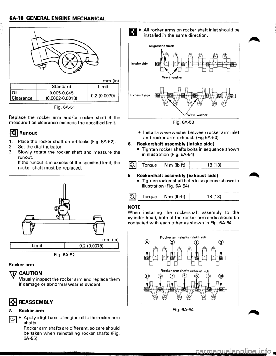
Oil
Clearance
Standard
0.005-0.045
(0.0002-0.0018)
Fig. 6A-51
mm (in)
Limit
0.2 (0.0079)
Replace the rocker arm and/or rocker shaft if the
measured
oil clearance exceeds the specified limit.
1~1 Runout
1. Place the rocker shaft on V-blocks (Fig. 6A-52).
2. Set the dial indicator.
3. Slowly rotate the rocker shaft and measure the
run out.
If the run out is in excess of the specified limit, the
rocker shaft
must be replaced.
mm (in)
Limit o.2 (o.oo79)
I
Fig. 6A-52
Rocker arm
wcAUTION
' Visually inspect the rocker arm and replace them
if damage or abnormal wear is evident.
l•!•l REASSEMBLY
7. Rocker arm
l'e::r.l • Apply a light coat of engine oil to the rocker arm
shafts.
Rocker arm shafts are different, so care
should
be taken when reinstalling rocker shafts (Fig.
6A-55).
All rocker arms on rocker shaft inlet should be
installed in the same direction.
AI ignment mark
Intake side
Wave washer
Exhaust side
6.
Fig. 6A-53
• Install a wave washer between rocker arm inlet
and rocker arm exhaust. (Fig 6A-53)
Rockershaft assembly (Intake side)
• Tighten rocker shafts bolts in sequence shown
in
illustration (Fig. 6A-54).
I~I __ To_r_q_ue ___ N_·_m_(_lb_·ft_)~l ______ 18_(_1_3) ____ _
5. Rockershaft assembly (Exhaust side) ~
• Tighten rocker shaft bolts in sequence shown in
illustration (Fig. 6A-54)
~~~ Torque N·m (lb·ft) I 18 (13)
NOTE
When installing the rockershaft assembly to the
cylinder head, both of the rocker arm ends should be
contacted
with each other as shown in Fig. 6A-54.
Rocker arm shafts intake side
Rocker arm shafts exhaust side
Fig. 6A-54
•
Page 538 of 1928
.r Ti
6A-22 GENERAL ENGINE MECHANICAL
6. Plug
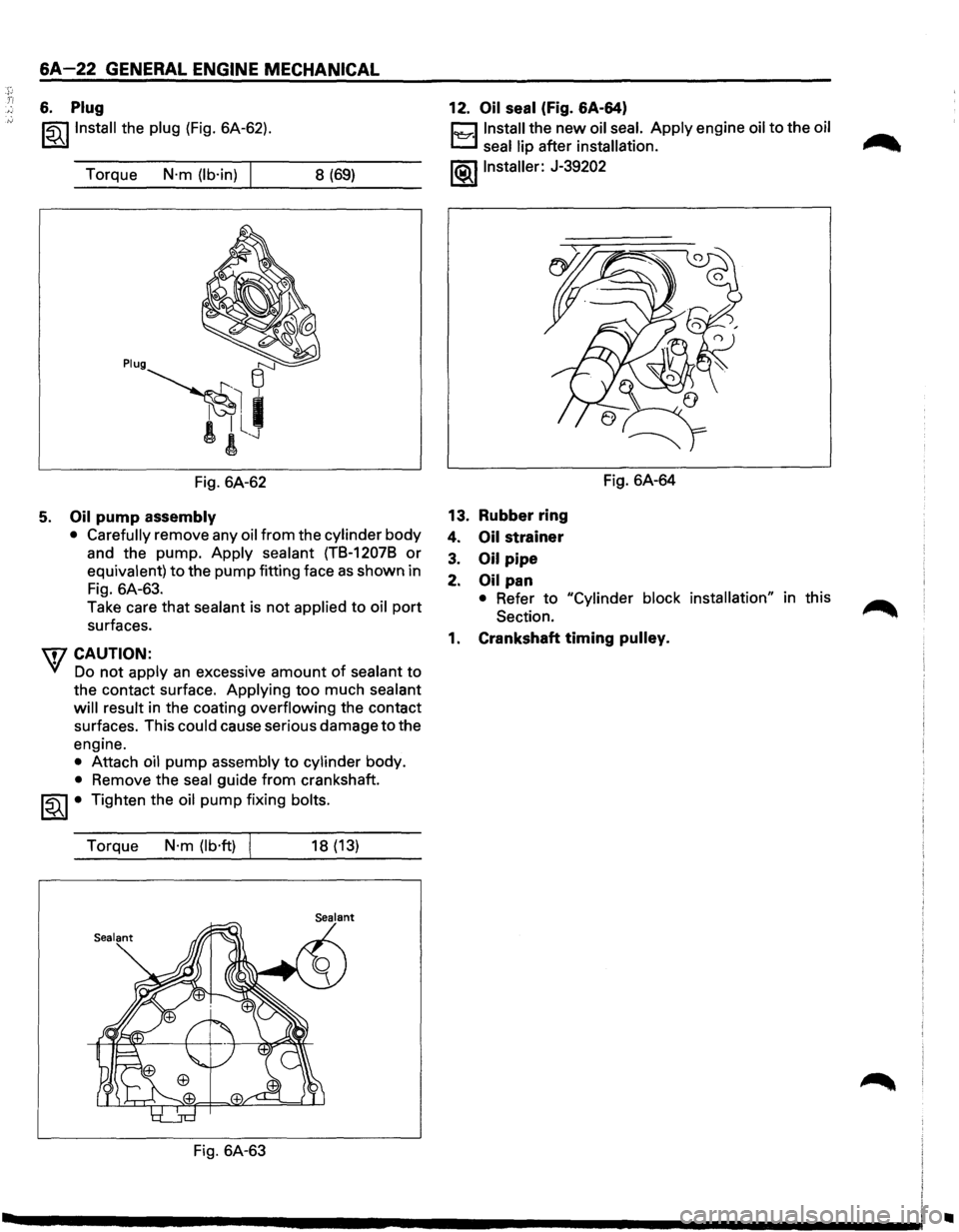
~~~Install the plug (Fig. 6A-62).
Torque
N·m (lb·in) 8 (69)
Fig. 6A-62
5. Oil pump assembly
• Carefully
remove any oil from the cylinder body
and the pump. Apply sealant (TB-12078 or
equivalent) to the pump fitting face as shown in
Fig. 6A-63.
Take care that sealant is
not applied to oil port
surfaces.
\fl CAUTION:
VI Do not apply an excessive amount of sealant to
the contact surface. Applying
too much sealant
will result in the coating overflowing the contact
surfaces. This could cause serious damage
to the
engine.
• Attach oil pump assembly to cylinder body.
• Remove the seal guide from crankshaft.
~~~ • Tighten the oil pump fixing bolts.
Torque
N·m (lb·ft) 18 (13)
Fig. 6A-63 12.
Oil
seal (Fig. 6A-64)
Cl Install the new oil seal. Apply engine oil to the oil
t..:::::::.l seal lip after installation.
~~~Installer: J-39202
13. Rubber ring
4. Oil strainer
3. Oil pipe
2. Oil pan Fig.
6A-64
• Refer to "Cylinder block installation" in this
Section.
1. Crankshaft timing pulley.
..
Page 541 of 1928
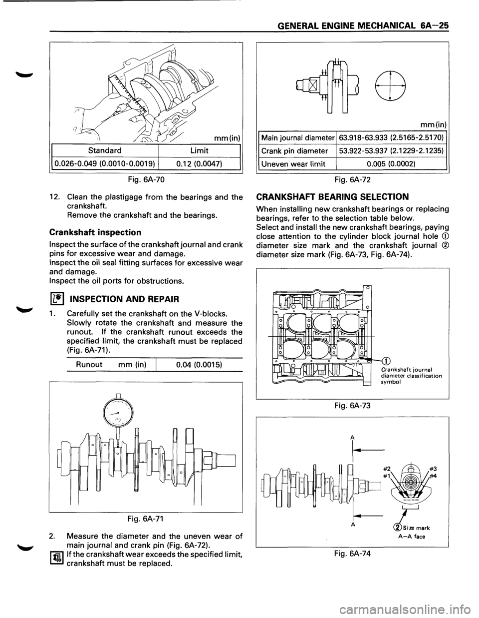
mm(in)
Standard Limit
0.026-0.049 (0.001 0-0.0019) 0.12 (0.0047)
Fig. 6A-70
12. Clean the plastigage from the bearings and the
crankshaft.
Remove the crankshaft and the bearings.
Crankshaft inspection
Inspect the surface ofthe crankshaft journal and crank
pins
for excessive wear and damage.
Inspect the oil seal fitting surfaces for excessive wear
and damage.
Inspect the oil ports for obstructions.
(L!] INSPECTION AND REPAIR
1. Carefully set the crankshaft on the V-blocks.
Slowly
rotate the crankshaft and measure the
runout.
If the crankshaft runout exceeds the
specified
limit, the crankshaft must be replaced
(Fig. 6A-71).
Runout
mm (in) 0.04 (0.0015)
Fig. 6A-71
2. Measure the diameter and the uneven wear of
main journal and crank pin (Fig. 6A-72).
l'fil If the crankshaft wear exceeds the specified limit,
~ crankshaft must be replaced.
GENERAL ENGINE MECHANICAL &A-25
mm(in)
Main
journal diameter 63.918-63.933 (2.5165-2.5170)
Crank pin diameter 53.922-53.937 (2.1229-2.1235)
Uneven wear
limit 0.005
(0.0002)
Fig. 6A-72
CRANKSHAFT BEARING SELECTION
When installing new crankshaft bearings or replacing
bearings, refer to the selection table below.
Select
and install the new crankshaft bearings, paying
close attention to the cylinder block journal hole
diameter size mark (Fig. 6A-73, Fig. 6A-74).
Fig. 6A-73
Crankshaft journal diameter classification symbol
1-----
#2~#3 #1 #4
~ --:--
A ;:.,,
A-A face
Fig. 6A-74