lock ISUZU TROOPER 1995 Workshop Manual
[x] Cancel search | Manufacturer: ISUZU, Model Year: 1995, Model line: TROOPER, Model: ISUZU TROOPER 1995Pages: 1928
Page 543 of 1928
l•!•l REASSEMBL V
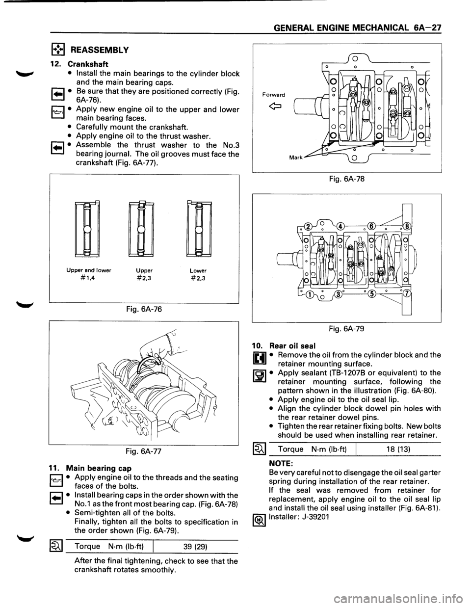
12. Crankshaft
• Install the main bearings to the cylinder block
and the main bearing caps.
1 .. 1• Be sure that they are positioned correctly (Fig.
6A-76).
1~1· Apply new engine oil to the upper and lower
main bearing faces.
• Carefully mount the crankshaft.
• Apply engine oil to the thrust washer.
1 .. 1• Assemble the thrust washer to the No.3
bearing
journal. The oil grooves must face the
crankshaft (Fig. 6A-77).
Upper and lower
#1.4
~
~
IH
t=
Upper
#2,3
Fig. 6A-76
Fig. 6A-77
11. Main bearing cap
Lower
#2,3
B • Apply engine oil to the
threads and the seating
' faces
of the bolts.
r=1 • Install bearing caps in the order shown with the
L:::.l No.1 as the front most bearing cap. (Fig. 6A-78)
• Semi-tighten all of the bolts.
Finally,
tighten all the bolts to specification in
the
order shown (Fig. 6A-79).
1~1 Torque N·m (lb·ft) 39 (29)
After the final tightening, check to see that the
crankshaft rotates
smoothly.
GENERAL ENGINE MECHANICAL 6A-27
Forward
Fig. 6A-78
Fig. 6A-79
10. Rear oil seal
liill • Re~ove the oil_from the cylinder block and the
U retainer mounting surface.
rEil • Apply sealant (TB-1207B or equivalen_t) to the
1.:::!!.1 retainer mounting surface, follow~ng the
pattern shown in the
illustration (Fig. 6A-80).
• Apply engine oil to the oil seal lip.
• Align
the cylinder block dowel pin holes with
the rear retainer dowel pins.
• Tighten the rear retainer fixing bolts. New bolts
should
be used when installing rear retainer.
~~~ Torque N·m (lb·ft) 18 (13)
NOTE:
Be very careful notto disengage the oil seal garter
spring during
installation of the rear retainer.
If the seal was removed from retainer for
replacement, apply engine oil to the oil seal lip
and install the oil seal using installer (Fig. 6A-81).
l®llnstaller: J-39201
Page 544 of 1928
6A-28 GENERAL ENGINE MECHANICAL
Fig. 6A-80
/
Fig. 6A-81
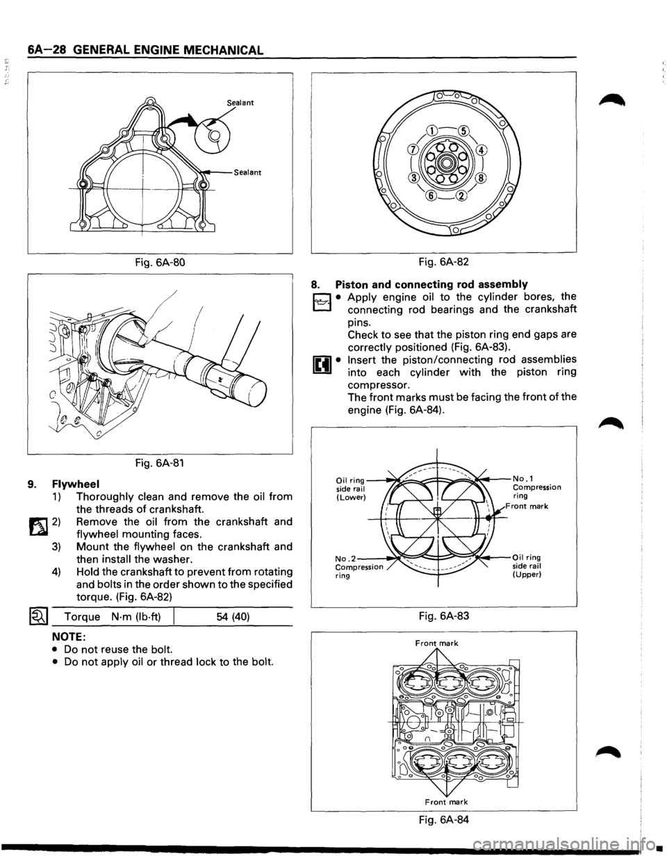
9. Flywheel
1) Thoroughly clean and remove the oil from
the threads
of crankshaft.
1!t1 2) Remove the oil from the crankshaft and
LQI flywheel mounting faces.
3) Mount the flywheel on the crankshaft and
then
install the washer.
4) Hold the crankshaft to prevent from rotating
and
bolts in the order shown to the specified
torque. (Fig. 6A-82)
~~~ Torque N·m (lb·ft) I ___ ___,_ ___ _ 54 (40)
NOTE:
• Do not reuse the bolt.
•
Do not apply oil or thread lock to the bolt.
Fig. 6A-82
8. Piston and connecting rod assembly
D • Apply engine oil to the cylinder bores, the
l:J connecting rod bearings and the crankshaft
pins. Check to see that the piston ring end gaps are
correctly positioned (Fig. 6A-83).
Insert the piston/connecting rod assemblies
into each cylinder with the piston ring
compressor. The
front marks must be facing the front of the
engine (Fig. 6A-84).
Oil ring ---~====-~::F::::::.===~~t---No. 1
side rail Compression (Lower) ring Front mark
No .2--~~:::::=:e!::::!-;::::!!;~~·-Oil ring
Compression side rail ring (Upper)
Fig. 6A-83
Front mark
Front mark
Fig. 6A-84
•
Page 547 of 1928
J-24086-SA ~---Press ram
Fig. 6A-90
10. Piston
11. Connecting rod
[1!) INSPECTION AND REPAIR
PISTON
AND PISTON RING
Pistons
Piston
Carefully clean away all the carbon adhering to the
piston head and the piston ring grooves.
NOTE:
Never use a wire brush to clean the pistons. Damage
will result.
Visually
check each piston for cracking, scoring, and
other signs
of excessive wear.
If any of the above conditions are present, the piston
must be replaced.
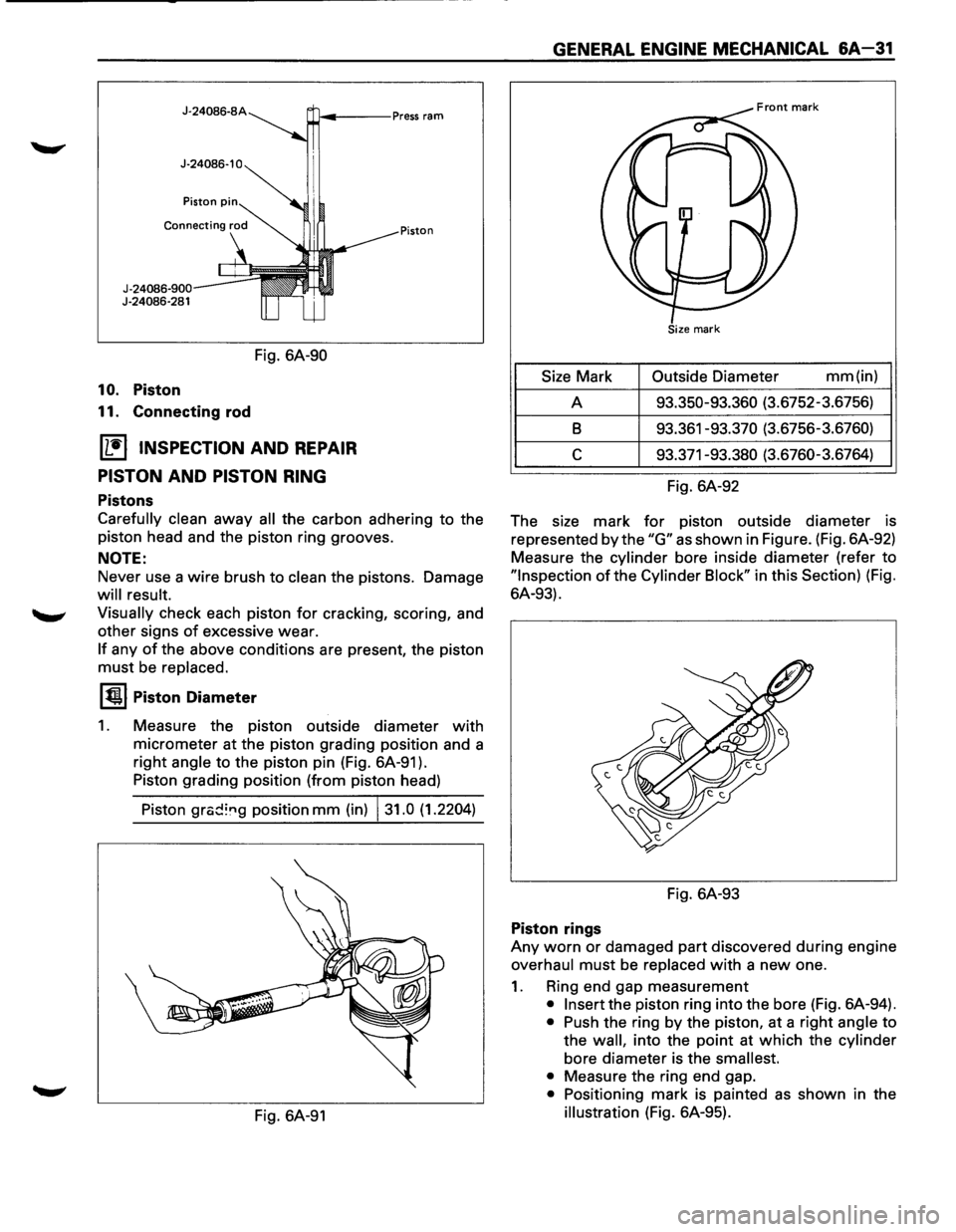
1~1 Piston Diameter
1. Measure the piston outside diameter with
micrometer at the piston grading position and a
right
angle to the piston pin (Fig. 6A-91 ).
Piston grading position (from piston head)
Piston
grc;d~"g position mm (in) 131.0 (1.2204)
Fig. 6A-91
GENERAL ENGINE MECHANICAL &A-31
Size Mark Outside
Diameter mm (in)
A 93.350-93.360 (3.6752-3.6756)
8 93.361 -93.370 (3.6756-3.6760)
c 93.371-93.380 (3.6760-3.6764)
Fig. 6A-92
The size mark
for piston outside diameter is
represented
by the "G" as shown in Figure. (Fig. 6A-92)
Measure the
cylinder bore inside diameter (refer to
"Inspection of the Cylinder Block" in this Section) (Fig.
6A-93).
Fig. 6A-93
Piston rings
Any worn or damaged part discovered during engine
overhaul must be replaced with a new one.
1. Ring end gap measurement
• Insert the piston ring into the bore (Fig. 6A-94).
• Push the ring by the piston, at a right angle to
the
wall, into the point at which the cylinder
bore diameter is the smallest.
•
Measure the ring end gap.
• Positioning mark is painted as shown in the
illustration (Fig. 6A-95).
Page 553 of 1928
GENERAL ENGINE MECHANICAL 6A-37
CYLINDER BLOCK
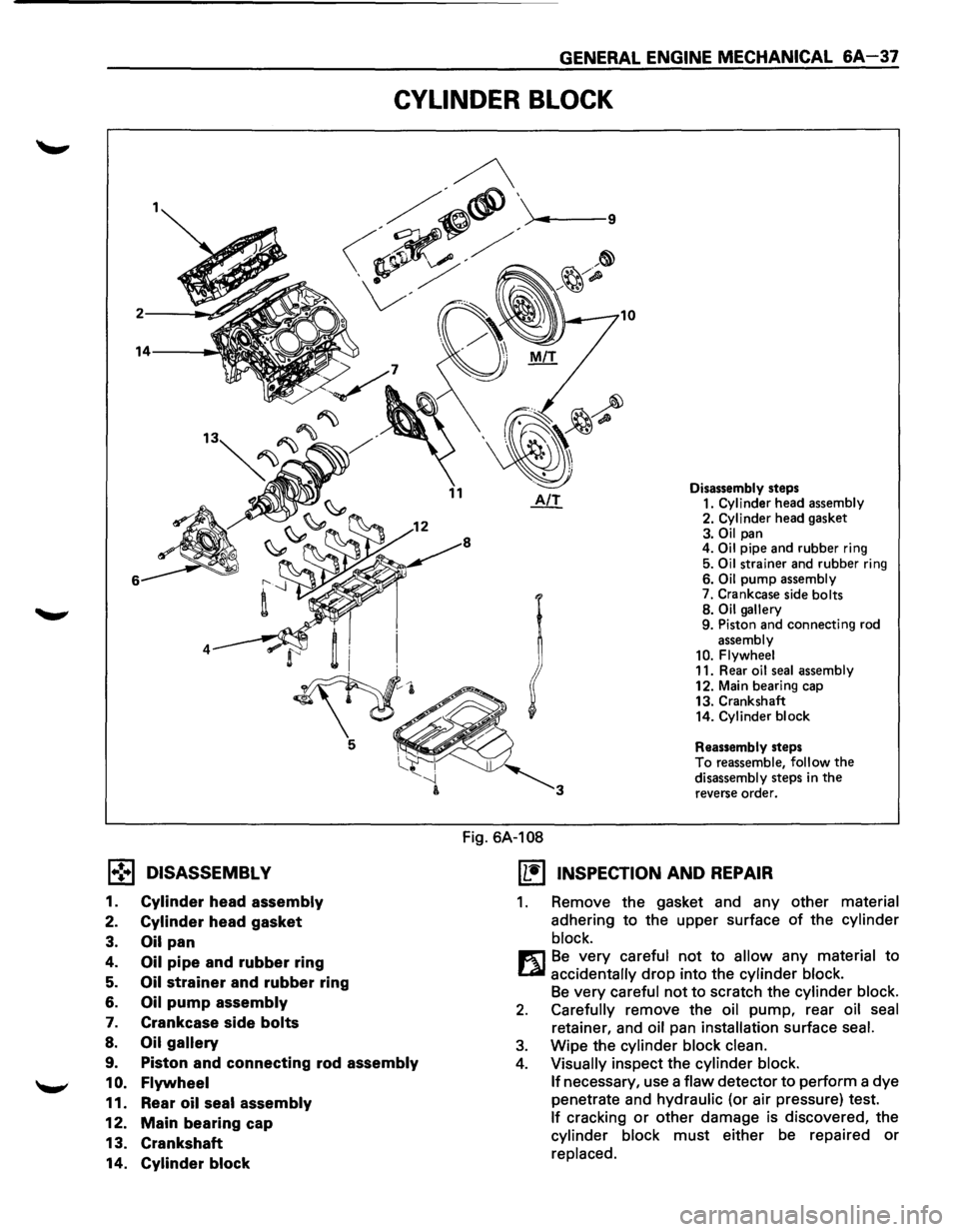
1.,!•1 DISASSEMBL V
1. Cylinder head assembly
2. Cylinder head gasket
3. Oil pan
4. Oil pipe and rubber ring
5. Oil strainer and rubber ring
6. Oil pump assembly
7. Crankcase side bolts
8. Oil gallery
9. Piston and connecting rod assembly
1 0. Flywheel
11. Rear oil seal assembly
12. Main bearing cap
13. Crankshaft
14.
Cylinder block
Fig. 6A-108
Disassembly steps
1. Cylinder head assembly
2. Cylinder head gasket
3. Oil pan
4. Oil pipe and rubber ring
5.
Oil strainer and rubber ring
6. Oil pump assembly
7. Crankcase side bolts
8.
Oil gallery
9. Piston and connecting rod
assembly
10. Flywheel
11. Rear oil seal assembly
12. Main bearing cap
13. Crankshaft
14.
Cylinder block
Reassembly steps
To reassemble, follow the disassembly steps in the reverse order.
(1!] INSPECTION AND REPAIR
1. Remove the gasket and any other material
adhering to the upper surface of the cylinder
block.
m Be very careful not to allow any material to
LQI accidentally drop into the cylinder block.
Be very careful not to scratch the cylinder block.
2. Carefully remove the oil pump, rear oil seal
retainer, and oil pan installation surface seal.
3. Wipe the cylinder block clean.
4. Visually inspect the cylinder block.
If
necessary, use a flaw detector to perform a dye
penetrate and
hydraulic (or air pressure) test.
If cracking or other damage is discovered, the
cylinder block must either be repaired or
replaced.
Page 554 of 1928
L
6A-38 GENERAL ENGINE MECHANICAL
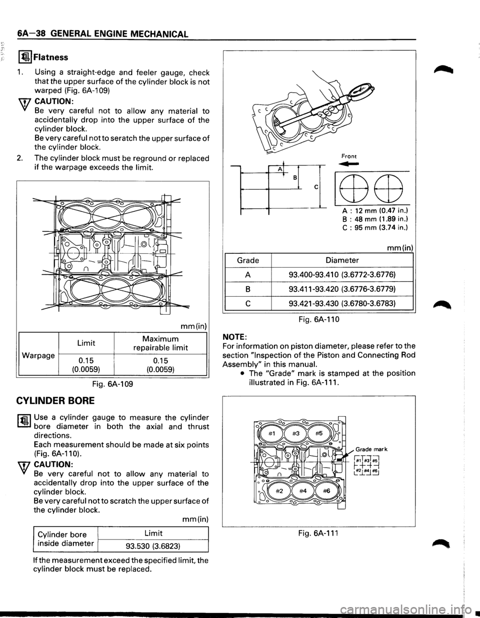
I @.I Flatness
1. Using a straight-edge and feeler gauge, check
that the upper surface of the cylinder block is not
warped (Fig.
6A-109)
\fl CAUTION:
VI Be very careful not to allow any material to
accidentally drop into the upper surface of the
cylinder block.
Be very careful not to seratch the upper surface of
the cylinder block.
2. The cylinder block must be reground or replaced
if the warpage exceeds the limit.
Warpage Limit 0.15
(0.0059)
mm(in)
Maximum
repairable limit
0.15
(0.0059)
Fig. 6A-1 09
CYLINDER BORE
l'fil Use a cylinder gauge to measure the cylinder
1..!:.1 bore diameter in both the axial and thrust
directions.
Each measurement
should be made at six points
(Fig. 6A-110).
\fl CAUTION:
VI Be very careful not to allow any material to
accidentally drop into the upper surface of the
cylinder block.
Be very careful not to scratch the upper surface of
the cylinder block.
Cylinder
bore
inside diameter Limit
93.530 (3.6823) mm(in)
lfthe measurement
exceed the specified limit, the
cylinder block must be replaced.
j -A] I B
c
--~ lED ED
A : 12 mm (0.47 in.)
B : 48 mm (1.89 in.)
C : 95 mm (3.74 in.)
mm(in)
Grade Diameter
A 93.400-93.41
0 (3.6772-3.6776)
B 93.411-93.420 (3.6776-3.6779)
c 93.421-93.430 (3.6780-3.6783)
Fig.
6A-110
NOTE:
For information on piston diameter, please refer to the
section
"Inspection of the Piston and Connecting Rod
Assembly" in this manual.
•
The "Grade" mark is stamped at the position
illustrated in Fig. 6A-111.
Grade mark
-+lllf++---+-+1-'--"--tt.:-H----:!+--~=rt--r;,T#;T ;1 ~+=+=J ~~~
Fig. 6A-111
•
Page 555 of 1928
1,.!.,1 REASSEMBLY
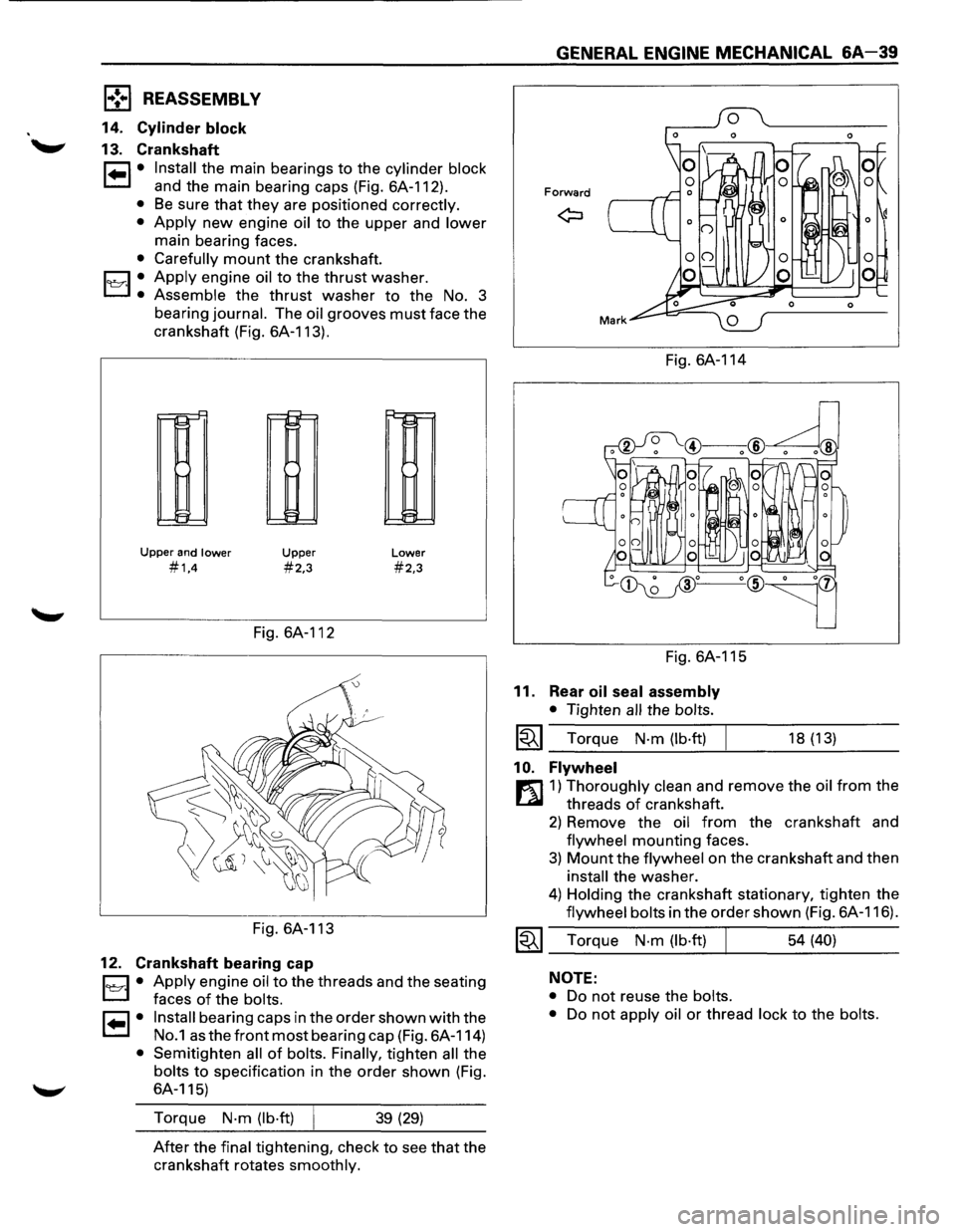
14. Cylinder block
13. Crankshaft
1•1• Install the main bearings to the cylinder block
and the main bearing caps (Fig. 6A-112).
• Be sure that they are positioned correctly.
•
Apply new engine oil to the upper and lower
main bearing faces.
• Carefully mount the crankshaft.
1~·1 .• Apply engine oil to the thrust washer.
Assemble the thrust washer to the No. 3
bearing
journal. The oil grooves must face the
crankshaft (Fig. 6A-113).
r--!::"
11-1
~
Upper and lower
#1,4
Upper
#2,3
Fig. 6A-112
Fig. 6A-113
12. Crankshaft bearing cap
Lower
#2,3
D • Apply engine oil to the threads and the seating
L:J faces of the bolts.
I• I• Install bearing caps in the order shown with the
No.1 as the front most bearing cap (Fig. 6A-114)
• Semitighten all of bolts. Finally, tighten all the
bolts to specification in the order shown (Fig.
6A-115)
Torque
N·m (lb·ft) 39 (29)
After the final tightening, check to see that the
crankshaft rotates
smoothly.
GENERAL ENGINE MECHANICAL &A-39
Forward
Fig. 6A-114
Fig. 6A-115
11. Rear oil seal assembly
• Tighten all the bolts.
~~~ Torque N·m (lb·ft)
1 0. Flywheel
18 (13)
r:l]1) Thoroughly clean and remove the oil from the
threads
of crankshaft.
2) Remove the oil from the crankshaft and
flywheel mounting faces.
3) Mount the flywheel on the crankshaft and then
install the washer.
4) Holding the crankshaft stationary, tighten the
flywheel bolts in the order shown (Fig. 6A-116).
~~~ Torque N·m (lb·ft) 54 (40)
NOTE:
•
Do not reuse the bolts.
•
Do not apply oil or thread lock to the bolts.
Page 559 of 1928
ENGINE (V6 3.2L DOHC AND SOHC) 6A 1-1
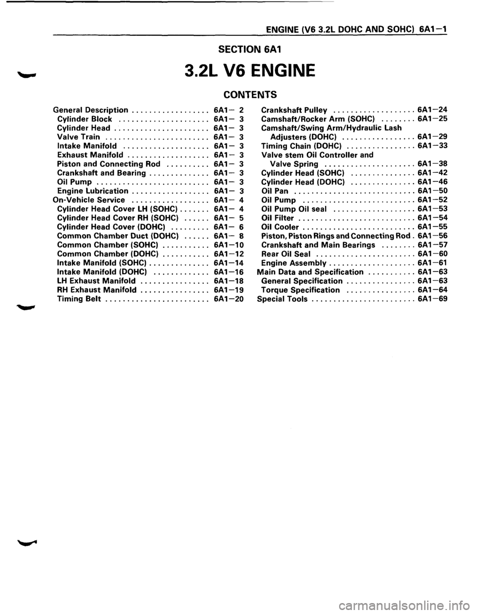
SECTION 6A1
3.2L V6 ENGINE
CONTENTS
General Description .................. 6A1-2 Crankshaft Pulley ................... 6A1-24
Cylinder Block . . . . . . . . . . . . . . . . . . . . . 6A 1-3 Camshaft/Rocker Arm (SOHC) ........ 6A1-25
Cylinder Head ...................... 6A1-3 Camshaft/Swing Arm/Hydraulic Lash
Valve Train ........................ 6A1-3 Adjusters (DOHC) ................. 6A1-29
Intake Manifold .................... 6A1-3 Timing Chain (DOHC) ................ 6A1-33
Exhaust Manifold ................... 6A1-3 Valve stem Oil Controller and
Piston and
Connecting Rod .......... 6A1-3 Valve Spring ..................... 6A1-38
Crankshaft and Bearing .............. 6A1-3 Cylinder Head (SOHC) ............... 6A1-42
Oil Pump .......................... 6A1-3 Cylinder Head (DOHC) ............... 6A1-46
Engine Lubrication . . . . . . . . . . . . . . . . . . 6A 1-3 Oil Pan ............................ 6A 1-50
On-Vehicle Service . . . . . . . . . . . . . . . . . . 6A1-4 Oil Pump .......................... 6A 1-52
Cylinder Head Cover LH (SOHC) ....... 6A1-4 Oil Pump Oil seal ................... 6A 1-53
Cylinder Head Cover RH (SOHC) ...... 6A1-5 Oil Filter ........................... 6A 1-54
Cylinder Head Cover (DOHC) . . . . . . . . . 6A 1-6 Oil Cooler .......................... 6A 1-55
Common Chamber Duct (DOHC) ...... 6A1-8 Piston, Piston Rings and Connecting Rod . 6A 1-56
Common Chamber (SOHC) ........... 6A1-10 Crankshaft and Main Bearings ........ 6A1-57
Common Chamber (DOHC) ........... 6A1-12 Rear Oil Seal ....................... 6A1-60
Intake Manifold (SOHC) .............. 6A1-14 Engine Assembly .................... 6A1-61
Intake Manifold (DOHC) ............. 6A1-16 Main Data and Specification ........... 6A1-63
LH Exhaust Manifold . . . . . . . . . . . . . . . . 6A 1-18 General Specification ................ 6A 1-63
RH Exhaust Manifold ................ 6A1-19 Torque Specification ................ 6A1-64
Timing Belt ........................ 6A1-20 Special Tools ........................ 6A1-69
Page 561 of 1928
CYLINDER BLOCK
The cylinder block is made of aluminum die-cast
casting
for 75° V-type six cylinders. It has a rear plate
integrated structure and employs a deep skirt. The
cylinder liner is cast and the liner inner diameter and
crankshaft
journal diameter are classified into grades.
The crankshaft is supported by four bearings
of which
width is different between No.2, No.3 and No.1, No.4;
the
width of No.3 bearing on the body side is different
in order
to support the thrust bearing. The bearing cap
is made
of nodular cast iron and each bearing cap uses
four bolts and two side bolts.
CYLINDER HEAD
The cylinder head, made of aluminum alloy casting
employs a pent-roof type combustion chamber with a
spark
plug in the center.
The intake and exhaust
valves are placed in V-type
design. The ports are cross-flow type.
VALVE TRAIN
SOHC: The camshafts on both banks are driven by a
timing
belt to operate the valves via rocker arm.
No
further valve clearance adjustment is
required, due
to the Hydraulic lash adjuster
attachedtotherockerarm.
DOHC: Intake camshaft on the both sides of banks are
driven through a
timing belt, while exhaust
camshaft are driven by the both sides
of intake
camshaft through chains.
The driven camshafts open and
close valves
through swing arms.
Valve clearance is automatically adjusted by
means
of HLA built in the cylinder head.
INTAKE MANIFOLD
SOHC: The intake manifold system is composed ofthe
aluminum cast common chamber and intake
manifold attached with six fuel injectors.
DOHC: The intake manifold system is composed of the
aluminum cast common chamber duct having
the induction
control valve, common chamber
and intake
manifold attached with six fuel
injectors.
EXHAUST MANIFOLD
The exhaust manifold is made of nodular cast iron.
PISTONS AND CONNECTING RODS
Aluminum pistons are used after selecting the grade
that meets the cylinder bore diameter. Each piston has
two compression rings and one oil ring. The piston pin
made
of chromium steel is offset 1 mm toward the
thrust side, and the thrust pressure
of piston to the
cylinder wall varies gradually as the piston travels. The
connecting rods are made
of forged steel. The
connecting rod bearings are graded
for correct size
selection.
ENGINE (V6 3.2L DOHC AND SOHC) 6A1-3
CRANKSHAFT AND BEARINGS
The crankshaft is made of Ductile cast-iron.Pins and
journals are graded for correct size selection for their
bearing.
OIL PUMP
The trochoid-type oil pump is driven by crankshaft.
Operation and service procedures are described in this
section.
ENGINE LUBRICATION
The oil discharged by a trochoid-type oil pump driven
by the crankshaft is fed through full-flow oil filter and
engine
coolant cooled oil cooler up to the oil gallery
provided under the crankshaft bearing cap. The oil is
then
led to the crankshaft journals and cylinder head.
The crank pins are
lubricated with oil from crankshaft
journals through oil holes. Also, an oil jet is fed to each
cylinder from crankshaft journals on the connecting
rod
for piston cleaning. The oil pan flange is sealed with
liquid packing only; do not deform or damage the
flange surface during removal or installation.
Page 580 of 1928
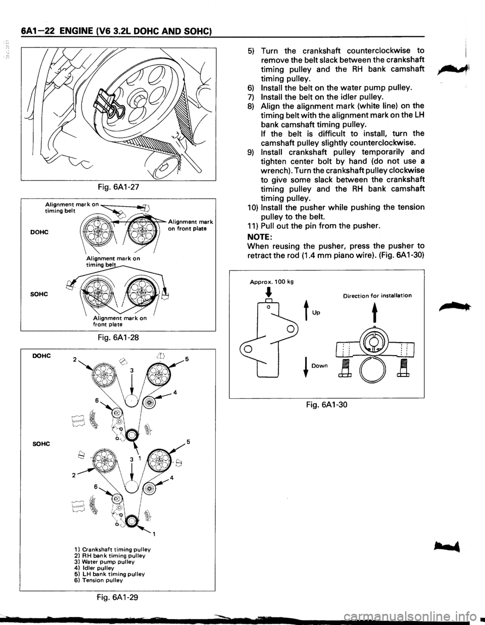
&A 1-22 ENGINE (V& 3.2L DOHC AND SOHC)
Fig. 6A1-27
Alignment mark on ~ timing belt ~
DOHC " ' on front plate
~~
Alignment mark
_","'
SOHC
DOHC
SOHC
/ Alignment mark on timing belt
Fig. 6A1-28
1) Crankshaft timing pulley 2) RH bank timing pulley 3) Water pump pulley 4) Idler pulley 5) LH bank timing pulley 6) Tension pulley
fig. 6A1-29
5) Turn the crankshaft counterclockwise to
remove the belt slack between the crankshaft
timing
pulley and the RH bank camshaft ,.......,,
timing pulley.
6) Install the belt on the water pump pulley.
7) Install the belt on the idler pulley.
8) Align the alignment mark (white line) on the
timing belt with the alignment mark on the
LH
bank camshaft timing pulley.
If
the belt is difficult to install, turn the
camshaft
pulley slightly counterclockwise.
9) Install crankshaft pulley temporarily and
tighten center bolt by hand (do
not use a
wrench). Turn the crankshaft
pulley clockwise
to give some slack between the crankshaft
timing
pulley and the RH bank camshaft
timing
pulley.
1 0) Install the pusher while pushing the tension
pulley to the belt.
11) Pull out the pin from the pusher.
NOTE:
When reusing the pusher, press the pusher to
retract the rod (1.4 mm piano wire). (Fig. 6A 1-30)
Approx. 100 kg
... Direction for installation
Fig. 6A1-30
,.. ..
•
Page 581 of 1928
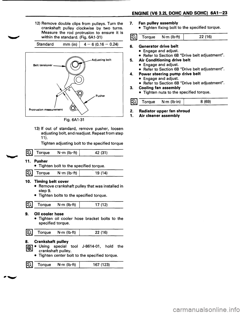
12) Remove double clips from pulleys. Turn the
crankshaft
pulley clockwise by two turns.
Measure the rod protrusion to ensure
it is
within the standard. (Fig. 6A 1-31)
Standard
mm (in) I 4 - 6 (0.16 -0.24)
Adjusting bolt
Pusher
Fig. 6A1-31
13) If out of standard, remove pusher, loosen
adjusting bolt, and readjust. Repeat from step
11 ).
Tighten adjusting bolt to the specified torque
1~1 Torque N·m (lb·ft) I 42 (31)
11. Pusher
• Tighten bolt to the specified torque.
1~1 Torque N·m (lb·ft) I 19 (14)
10. Timing belt cover
• Remove crankshaft pulley that was installed in
step
9.
• Tighten bolts to the specified torque.
~~~ Torque N·m (lb·ft) I 17 (12)
9. Oil cooler hose
• Tighten oil cooler hose bracket bolts to the
specified torque.
~~~ Torque N·m (lb·ft) I 22 (16)
8. Crankshaft pulley
l"iQ\1 • Using special tool J-8614-01, hold the
~ crankshaft pulley.
•
Tighten center bolt to the specified torque.
1~1 Torque N·m (lb·ft) 167 (123)
ENGINE (V6 3.2L DOHC AND SOHC) 6A1-23
7. Fan pulley assembly
• Tighten fixing bolt to the specified torque.
~~~ Torque N·m (lb·ft) 22 (16)
6. Generator drive belt
• Engage and adjust.
• Refer to Section 68 "Drive belt adjustment".
5. Air Conditioning drive belt
• Engage and adjust.
• Refer to Section 68 "Drive belt adjustment".
4. Power steering pump drive belt
• Engage and adjust.
• Refer to Section 68 "Drive belt adjustment".
3. Cooling fan assembly
• Tighten nuts to the specified torque.
~~~ Torque N·m (lb·in) I 8 (69)
2. Radiator upper fan shroud
1. Air cleaner assembly