sensor ISUZU TROOPER 1995 Workshop Manual
[x] Cancel search | Manufacturer: ISUZU, Model Year: 1995, Model line: TROOPER, Model: ISUZU TROOPER 1995Pages: 1928
Page 1237 of 1928
CHASSIS ELECTRICAL 8-47
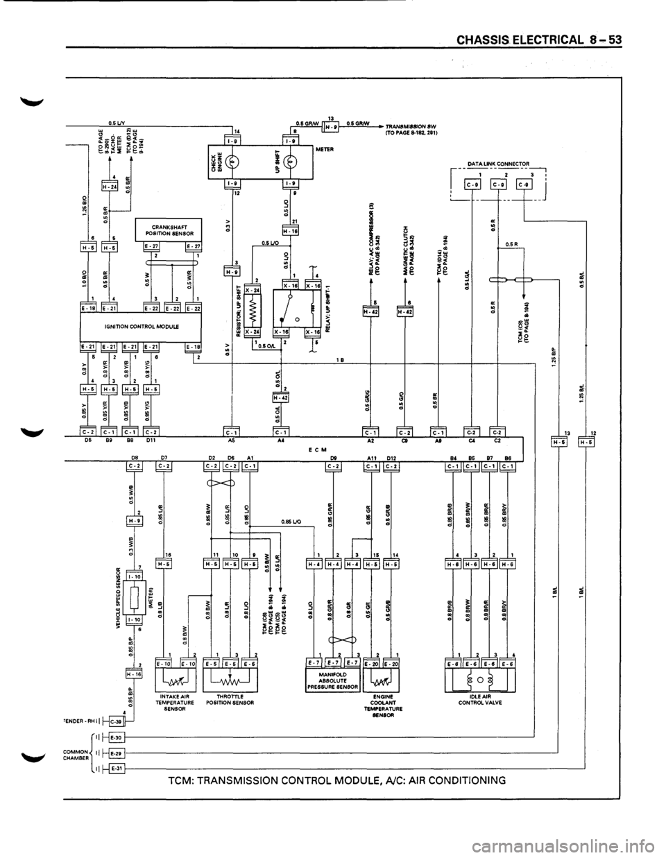
ENGINE CONTROL MODULE (ECM)
GENERAL DESCRIPTION
The ECM is used to control the fuel system of the
vehicle, especially in controlling the following items.
1. FUEL CONTROL
The amount of fuel and air sent into the combus
tion chamber is controlled by controlling the fuel
sent through the injector.
2. ELECTRIC FUEL PUMP (INSTALLED IN
THE FUEL TANK)
The in-tank fuel pump is controlled by the ECM.
When starter switch is turned on, the pump will
run for 2 seconds, then stop unless the engine is
cranking
or running.
3. IGNITION CONTROL
The system is controlled by the spark timing con
trol function of the ECM.
4. CIRCULATION OF EXHAUST GAS
The system controls the formation of NOx by
returning a small amount of exhaust gas to the
intake manifold
through the control valve.
'-" lAC: Idle air control
5. CONTROL OF AIR CONDITIONING (A/C)
For improved engine idling performance, the sys
tem controls the operation of the air conditioner
by regulating the
clutch operation ofthe A/C com
pressor in accordance
with changes in operation.
6. IDLE AIR CONTROL
The system controls the lAC Valve for the desired
idle speed in accordance
with changes in
operation.
7. DIAGNOSIS OF TROUBLES
When a sensor detects any signal that the ECM is
in
an abnormal condition, the ECM turns on the
malfunction
indicator (CHECK ENGINE) light in
the meter, and stores at the same
time the corre
sponding diagnostic
trouble code (DTC) in the
memory to indicate to which system or circuit the
trouble represented by the
DTC belongs.
The ECM inspection connector (data link connec
tor) is used
to retrieve the DTCs stored from the
ECM.
Refer to Section 6 "ENGINE DIAGNOSIS" for de
tails.
Page 1238 of 1928
.~·-
, ca· CIO I O'l O'l
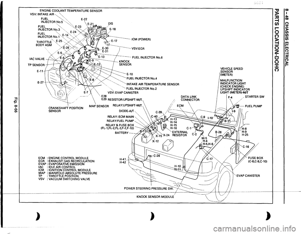
ENGINE
COOLANT TEMPERATURE SENSOR
VSV:
INTAKE
AIR~""-"-,
FUEL
~,
'"-
E-22
INJECTOR
No.5
'~~
FUEL
~
"':·.E-23
INJECTOR
No.3
"-
'"<
FUEL
"-
·,,,
E-~
4 /'
INJECTOR
No.'1'~-
1~4 "...
.......
. .......
' '
/
BODY
ASM
"-..'-
>
DIS / / E-18
ICM !POWER)
THROTILE '
E-~5·.-..,
.. '-, ·,/
r
E-2~,,
/E-5v~~;>o~~
--vsv:EGR
FUEL
INJECTOR
No.6
E-11
~E-10 ~FUEL
INJECTOR
No.4
E-27-+
"'
:1
~
.........
_
'-......
"·INTAKE
AIR TEMPERATURE SENSOR
ECM EGR EVAP
lAC
ICM MAP TP vsv )
X
·"
~
FUEL
INJECTOR
No.2
VSV: EVAP CANISTER
E28
E29
RESISTOR:UPSHIFT-M/T
CRANKSHAFT
POSITION
SENSOR
MAP
SENSOR RELAY:UPSHIFT-M/T ,
ENGINE
CONTROL
MODULE
EXHAUST GAS RECIRCULATION
EVAPORATIVE EMISSION IDLE
AIR CONTROL
IGNITION CONTROL
MODULE
MANIFOLD ABSOLUTE PRESSURE
THROTILE POSITION VACUUM
SWITCHING
VALVE
DIODE-AfT
'...,
RELAY:
ECM
MAIN
~"'-.,'...,
RELAY:FUEL
PUMP
'....
'
RELAY
& FUSE BOX
(FL-1,FL-2,FL-3,F-2,F-10)
BATIERY~
H-41 H-42~
KNOCK SENSOR
MODULE
)
DATA
LINK
CONNECTOR
VEHICLE
SPEED
SENSOR
(METER)
MALFUNCTION INDICATOR LIGHT (CHECK ENGINE) UPSHIFT INDICATOR LIGHT
(METER)-M/T
STARTER
SW
·~FUEL
PUMP
EVAP CANISTER
)
~
co I
~
~ co
(/)
0
r-
:::t
0
)> C/)
0
C/)
~
Cii
-
m
0
r-m
2
0
I
~
c
:a
0
0 )>
J:
r-
0
Page 1239 of 1928
!! (Q
(
FUEL INJECTOR
No.1
/
FUEL INJECTOR
No.5
FUEL INJECTOR
No.3
I
\/.
ICM
CPOWERl
_/
E-27
cp
I
CRANKSHAFT
~
POSITION SENSOR
ECM
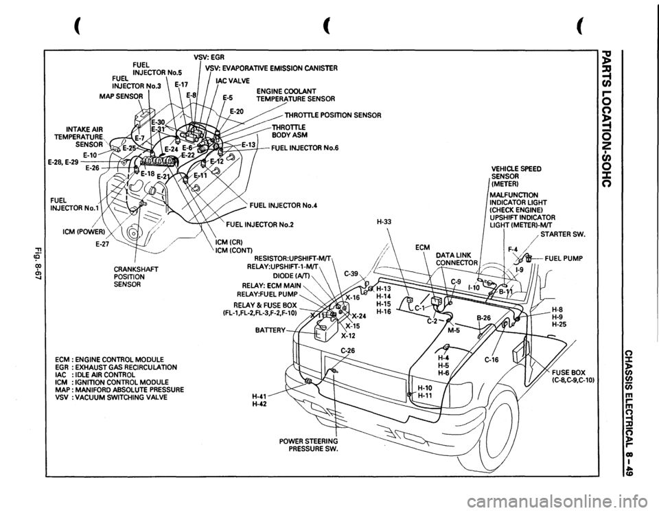
: ENGINE
CONTROL
MODULE
EGR
:EXHAUST
GAS
RECIRCULATION
lAC
: IDLE
AIR
CONTROL
ICM
: IGNmON
CONTROL
MODULE
MAP
: MAN
I FORD
ABSOLUTE
PRESSURE
VSV
:VACUUM
SWITCHING
VALVE
(
VSV:EGR I VSV:
EVAPORATIVE
EMISSION
CANISTER
THROTTLE
POSmON
SENSOR
~FUEL
INJECTOR
No.6
FUEL
INJECTOR
No.4
FUEL
INJECTOR
No.2
ICMCCRl ICMCCONTl
RESISTOR:UPSHIFT-MIT RELAY:UPSHIFT-1-MIT
DIODECAITl
RELAY:
ECM
MAIN
RELAY:FUEL
PUMP
RELAY
& FUSE
BOX
CFL-1,FL-2,FL-3,F-2,F-10l
H-41 H-42
POWER
STEERING
PRESSURE
SW.
H-33
VEHICLE
SPEED
SENSOR (METER) MALFUNCTION INDICATOR
LIGHT
(CHECK
ENGINE)
UPSHIFT
INDICATOR
LIGHT
CMETERl-MfT
(
/STARTER
SW.
F-4
/
DATA
LINK
I
d .
'v_AR__
FUEL
PUMP
CONNECTOR~
!P
~;~·
/~
,,
1-9
~ ~ r-0 n ~ 0 2 • en 0 X n
(") ::::1: )> CJ)
CJ) Cii m rm ~ :D ~ r-01) I fD
Page 1241 of 1928
w " ~~ O.SLJY ~ ..
2"' a~ u$ ~f~ ~~ ~g~
FENDER-RH II
DUCT II
~~~~~II
DUCT II
INTAKE AIR TEMPERATURE SENSOR
~~ 0~
a; d
0.89
C-1 A&
THROTTLE POSITION
SENSOR
... 5! ., .. ::> 0: ~
m
0.85LIO
~ a d d
li~Ui"o:i UOlUCJI> i;i;i:b ~wuw "'"" ~ ~ g g
"' il " Ill
13
§
; w 0 0: .. 5N ~;:; 8<:1 d~ u"' ~~ ~~ ~~ z< ., .. ~g ~g
~ § :;1 ~ d
0: " Ill d
ENGINE COOLANT
TEMPERATURE
SENSOR
CHASSIS ELECTRICAL 8-51
~ ~ ~w _.,
i£ ~g
~ i ;zf d
d
IIi ~ d .. :b
~~ ~g
~
"' ~ 5I d "'
13 12 H-6 H-6
.. ~ "' ~ il il
!
! ! ~
~ ~ I ~ CD ! ! ~
i
i
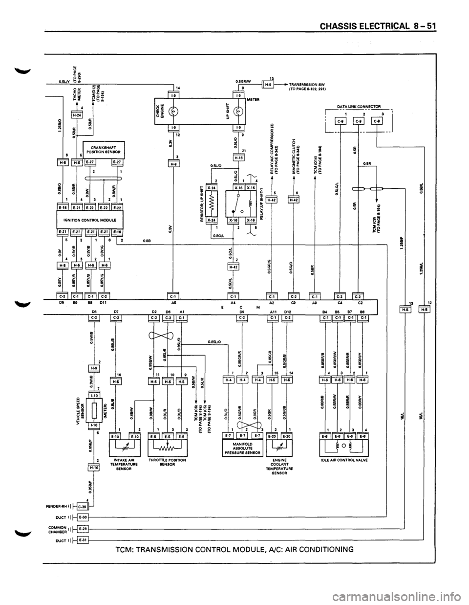
TCM: TRANSMISSION CONTROL MODULE, A/C: AIR CONDITIONING
Page 1243 of 1928
0.5 LJV
E C M
.. ~ ~ g ~ ::r <3 ::! ~ ~ IB Ill d 0 d 0.85 LJO d
16 10 ~ ~ H-6 ~ ~
: : 3 ~ ~ ;;; ;;; .. 3~ ~~ ~ " 0 ~ I -f -:
~I
~g~g
INTAKE AIR THROTTLE TEMPERATURE POSITION SENSOR
SENSOR
'ENDER-RH II
f-'0""·5,;G,RIN!!!!.__,~ TRANSMISSION SW (TO PAGE 8-182. 281)
a
~ .. % IE u 21<1 3~ i 8<=~
~= u .. ;;;
~~ '"'" ~~
_.., j§L e.~ 2o ll!g ig l:!t::
a: ~ i <3 <3 IB .. IB d
d
d
a: a: ~ ~ <3 " .. .. .. d d ~ ~
CHASSIS ELECTRICAL 8 ... 53
~ ... .. d
~ ..
~
~ .. ~
i IB d
~ .. ~
a: .. d
13 1Z H-5 H-5
i IB d
iil iil
~ .. .. 0
COMMON{::~------------------------------------------------------------------------------------------~ CHAMBER r·-l::.:!!J
II E-311-'----------------------------------------------------------------------------------------------~
TCM: TRANSMISSION CONTROL MODULE, A/C: AIR CONDITIONING
Page 1362 of 1928
8 -172 CHASSIS ELECTRICAL
CRUISE CONTROL
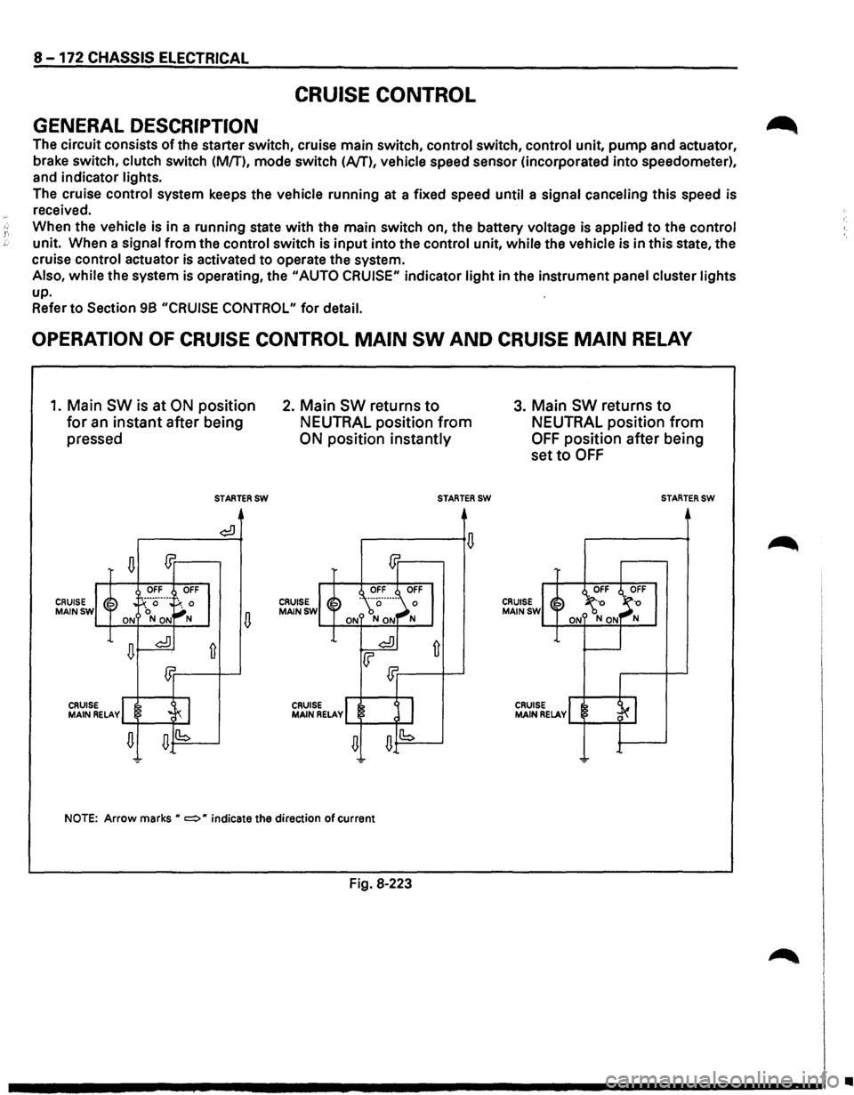
GENERAL DESCRIPTION
The circuit consists of the starter switch, cruise main switch, control switch, control unit, pump and actuator,
brake switch, clutch switch (M/T),
mode switch (Nf), vehicle speed sensor (incorporated into speedometer),
and indicator lights.
The cruise
control system keeps the vehicle running at a fixed speed until a signal canceling this speed is
received.
When the vehicle is in a running state with the main switch on, the battery voltage is applied to the control
unit. When a signal from the control switch is input into the control unit, while the vehicle is in this state, the
cruise control actuator is activated
to operate the system.
Also,
while the system is operating, the "AUTO CRUISE" indicator light in the instrument panel cluster lights
up.
Refer
to Section 98 "CRUISE CONTROL" for detail.
OPERATION OF CRUISE CONTROL MAIN SW AND CRUISE MAIN RELAY
1. Main SW is at ON position
for an instant after being
pressed
CRUISE MAINSW
n m
OFF OFF
~~ . !-':··a··---
~: 0 ON NON
n~
£Jr
CRUIS MAIN ~ELAvl .c~ I
n n(b
-
STARTERSW
¢:!)
fi
2. Main SW returns to
NEUTRAL position from
ON position instantly
CRUISE MAINSW
CRUISE MAIN RELAY
STARTERSW
NOTE: Arrow marks H c:::::> H indicate the direction of current
Fig. 8·223
3. Main SW returns to
NEUTRAL position from
OFF position after being
set
to OFF
CRUISE MAINSW
CRUISE MAIN RELAY
STARTERSW
..
Page 1363 of 1928
"TI ~· 00 I N N .,..
(
(
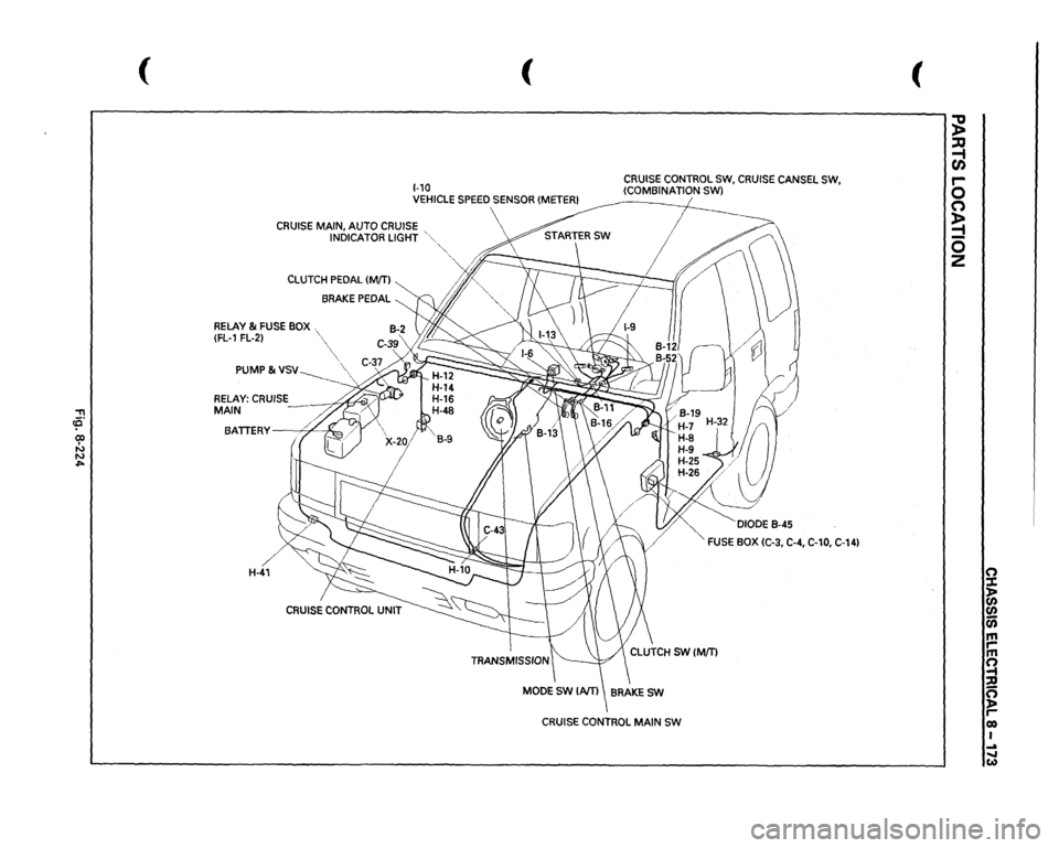
1-10 VEHICLE
SPEED
SENSOR
(METER!
CRUISE
CONTROL
SW,
CRUISE
CANSEL
SW,
(COMBINATION SWl
CRUISE
MAIN, AUTO
CRUISE
INDICATOR
LIGHT
'"
CLUTCH
PEDAL
(MfTI
BRAKE
PEDAL
RELAY
& FUSE
BOX
(FL-1
FL-2) PUMP
& VSV-------__
BATTERY
. '/
)",...
H-41
CRUISE
CONTROL
UNIT
·""·
'~~/{' /l/
'
4/
·,,_
DIODE
B-45
FUSE
BOX
(C-3,
C-4,
C-10,
C-14)
CRUISE
CONTROL
MAIN
SW
(
~ ::u ~ r-0 (") ~ 0 z
0 ::t > (/) (/) a; m ,.. m !l ::D 0 )> reo I ... ..... w
Page 1368 of 1928
8 -178 CHASSIS ELECTRICAL
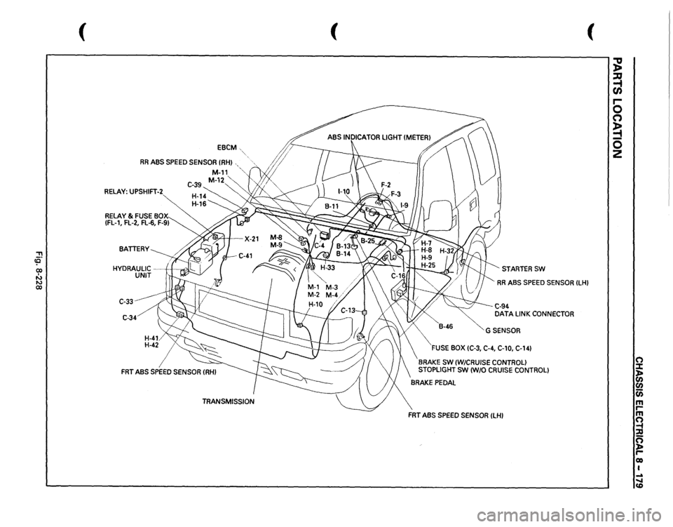
ANTI-LOCK BRAKE SYSTEM (ABS)
GENERAL DESCRIPTION
The circuit consists of the starter switch, stoplight switch (vehicle w/o cruise control), brake switch (vehicle
with cruise control), hydraulic unit, electronic brake control module, wheel speed sensor, G sensor, ABS and
4WD indicator, 4WD switch and data link connector.
When the service brake is applied while in the running mode,
the EBCM (Electronic Brake Control Module)
judges
which wheel is about to lock by using the wheel rotation speed signals sent from the four ABS speed
sensors at the
front and rear wheels. And the brake fluid pressure applied to the four wheels is controlled by
a hydraulic unit to prevent the wheels from locking.
Based on the wheel rotation speed signals
input from the ABS sensor, the EBCM sends out signals to the
solenoid valve in the hydraulic unit
to increase, maintain or decrease the brake fluid pressure. The solenoid
valve uses this signal
to control the fluid pressure which is applied to the calipers of the disk brakes of the
front wheels. (The system also controls at the same time the fluid pressure applied to the rear wheels.)
• EBCM (Electronic brake control module)
The EBCM uses the signals sent from the speed sensor to control the operation of the hydraulic unit.
When any malfunction occurs in the ABS, the
EBCM activates the fail-safe fuction while turning on the
ABS warning light.
• Hydraulic unit
The hydraulic unit consists of the motor, plunger pump, solenoid valve, and fluid pressure control
valves. The exterior
of the unit has a relay box consisting of the motor relay and valve relay. Three
solenoid valves, the
two of which are provided at the front wheels and the one at the rear wheels, control
the fluid pressure
of these wheels.
• Speed sensor
The speed sensor consists of the sensor and the rotor. It sends the EBCM the AC voltage generated by
the rotation of the rotor as the vehicle speed signal. ~
• G-sensor
The G-sensor, installed inside the center console, sends out signals to the EBCM by detecting the
decelerating speed
of the vehicle.
• ABS warning light
The ABS warning light in the instrument panel, lights up when any malfunction occurs in the ABS. It also
lights up
with the starter key at the "ON" position, as a self-check.
Refer
to Section 5A4, "ANTI-LOCK BRAKE SYSTEM" for detail.
II
Page 1369 of 1928
::!! (Q 00 I N N 00
(
EBCM
RR
ABS
SPEED
SENSOR
(RHI
RELAY:
UPSHIFT-2
C-33 C-34
(
(
STARTERSW RR
ABS
SPEED
SENSOR
ILHI
C-94 DATA
LINK
CONNECTOR
GSENSOR
FUSE
BOX
(C-3,
C-4,
C-10,
C-141
BRAKE
SW
(W/CRUISE
CONTROL)
STOPLIGHT
SW
IW/0
CRUISE
CONTROL)
FRT
ABS
SPEED
SENSOR
ILHI
~ :a -t CJ) r-0 (") ~ 0 z
(") :::t ln en (i) m rm ~ :;g n ~ r-eo I ..a ..... CD
Page 1375 of 1928
CHASSIS ELECTRICAL 8-185
REAR WHEEL ANTI-LOCK BRAKE SYSTEM (RWAL)
GENERAL DESCRIPTION
The circuit consists of the starter switch, stoplight switch (vehicle w/o cruise control), brake switch (vehicle
w/cruise control). RWAL controller, RWAL speed sensor, RWAL valve, brake differential switch, 4WD switch,
parking brake
SW, indicator light (RWAL, 4WD, BRAKE), and test connector.
In this system, when the service brake is applied the RWAL controller judges the wheel rotation difference
signals which have been sent from the RWAL speed sensor at the rear axle differential. The anti-lock valves
control
the brake fluid pressure which is applied to the rear wheels to prevent the wheels from locking.
When starting the engine, the RWAL indicator in the instrument panel lights up at the same time as the brake
indicator
to inform the driver that the system is operating normally. (The light goes off after two seconds.)
Refer
to Section 5A3, "RWAL (REAR WHEEL ANTI-LOCK BRAKE SYSTEM)" for detail.