sensor ISUZU TROOPER 1995 Workshop Manual
[x] Cancel search | Manufacturer: ISUZU, Model Year: 1995, Model line: TROOPER, Model: ISUZU TROOPER 1995Pages: 1928
Page 1382 of 1928
8-192 CHASSIS ELECTRICAL
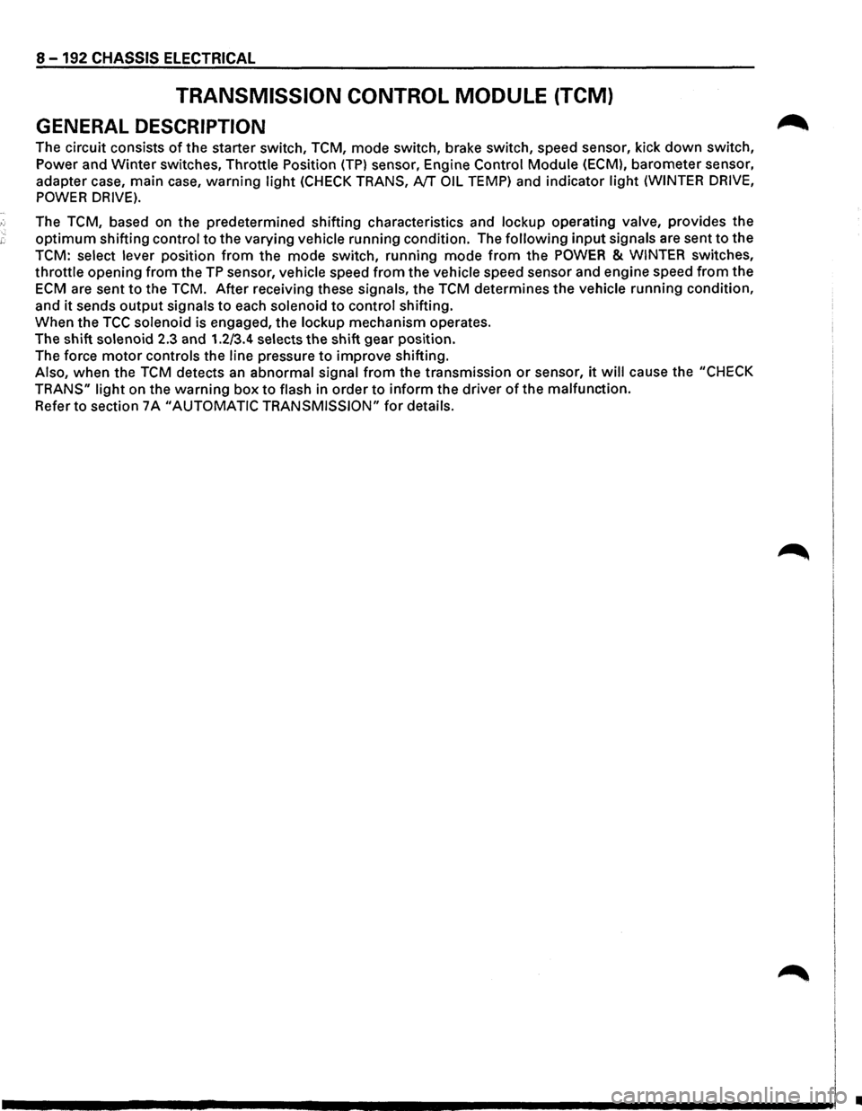
TRANSMISSION CONTROL MODULE (TCM)
GENERAL DESCRIPTION
The circuit consists of the starter switch, TCM, mode switch, brake switch, speed sensor, kick down switch,
Power and
Winter switches, Throttle Position (TP) sensor, Engine Control Module (ECM), barometer sensor,
adapter case, main case,
warning light (CHECK TRANS, NT OIL TEMP) and indicator light (WINTER DRIVE,
POWER DRIVE).
The TCM, based on the predetermined shifting characteristics and lockup operating valve, provides the
optimum shifting control to the varying vehicle running condition. The following input signals are sent to the
TCM: select lever position from the mode switch, running mode from the POWER & WINTER switches,
throttle opening from the TP sensor, vehicle speed from the vehicle speed sensor and engine speed from the
ECM are sent to the TCM. After receiving these signals, the TCM determines the vehicle running condition,
and
it sends output signals to each solenoid to control shifting.
When the
TCC solenoid is engaged, the lockup mechanism operates.
The shift
solenoid 2.3 and 1.2/3.4 selects the shift gear position.
The force
motor controls the line pressure to improve shifting.
Also, when the TCM detects an abnormal signal from the transmission or sensor, it will cause the "CHECK
TRANS"
light on the warning box to flash in order to inform the driver of the malfunction.
Refer to section 7 A "AUTOMATIC TRANSMISSION" for details.
•
Page 1383 of 1928
, cE" 00 I I'J w 00
(
FRONT
CONSOLE
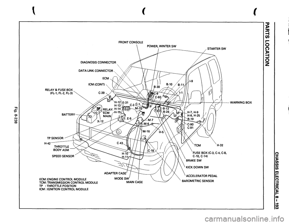
DIAGNOSIS
CONNECTOR
"~",
DATA
LINK
CONNECTOR,
·~
RELAY
& FUSE
BOX
(FL-1,
FL-2,
FL-3)
TPSENSOR H-42-
SPEED
SENSOR
ECM:
ENGINE
CONTROL
MODULE
ICM(CONT)
TCM:
TRANSMISSION
CONTROL
MODULE
TP
: THROTTLE
POSITION
ICM
: IGNITION
CONTROL
MODULE
~;
t I:;::==PI
v
/)
WARNING
BOX
' .
!I
/;;'
H-32
FUSE
BOX
(C-3,
C-4, C-8,
C-10,
C-14)
BRAKESW
KICKDOWNSW ACCELERATOR
PEDAL
BAROMETRIC
SENSOR
(
;g ~ en r-0 (") ~ 0 2
0 :::1: )> (I) (I) c;; m rm ~ :;Q ~ co I .... (D w
Page 1478 of 1928
8-288 CHASSIS ELECTRICAL
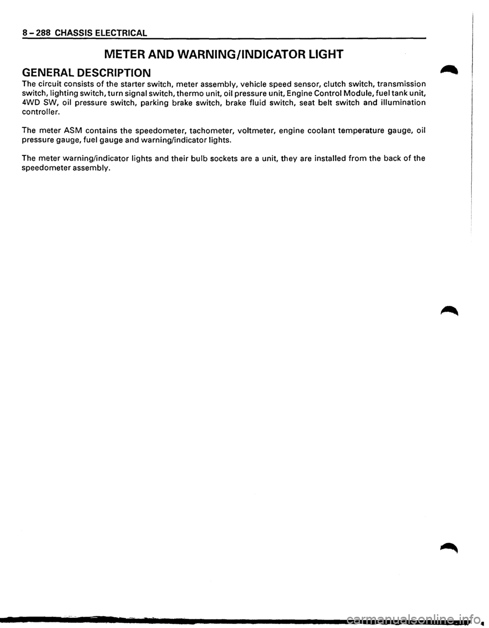
METER AND WARNING/INDICATOR LIGHT
GENERAL DESCRIPTION
The circuit consists of the starter switch, meter assembly, vehicle speed sensor, clutch switch, transmission
switch, lighting switch,
turn signal switch, thermo unit, oil pressure unit, Engine Control Module, fuel tank unit,
4WD
SW, oil pressure switch, parking brake switch, brake fluid switch, seat belt switch and illumination
controller.
The meter ASM contains the speedometer, tachometer, voltmeter, engine coolant temperature gauge, oil
pressure gauge, fuel gauge and warning/indicator lights.
The meter warning/indicator lights and
their bulb sockets are a unit, they are installed from the back of the
speedometer assembly.
Page 1479 of 1928
::!!
(
(
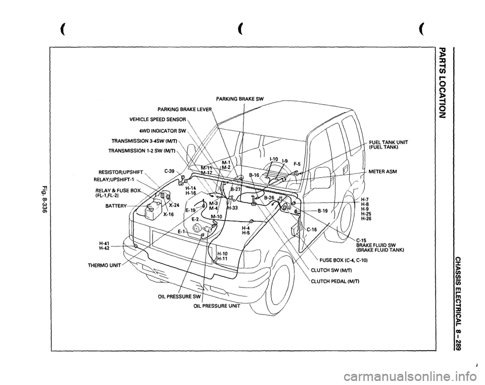
PARKING
BRAKE
SW
PARKING
BRAKE
LEVER
VEHICLE
SPEED
SENSOR
4WD
INDICATOR
SW,
~
' '
/;~>
TRANSMISSION
3-4SW
IMJT)
"vf;/
RESISTOR;UPSHIFT
."
RELAY;UPSHIFT-1
~":'""
RELAY
& FUSE
BOX-_
(FL-1
,FL-21 BA.
TTERY--.;:;4"~
H-41 H-42
-----;1-"'.,.,-~
THERMO
UNIT
FUEL
TANK
UNIT
(FUEL
TANK)
METERASM
~
16)
1 /
1
(
H-7
/'1'-J
? I n
H-8 H-9 H-25
H-26 C..15 BRAKE
FLUID
SW
(BRAKE
FLUID
TANK}
FUSE
BOX
IC-4,
C-10}
\CLUTCH
SW
(M/T)
CLUTCH
PEDAL
(Mm
(
~ ::xs ~ r-0 0 ~ -0 2
(") :X: ~ en (i) m rm (") ~ g roo I ~
Page 1484 of 1928
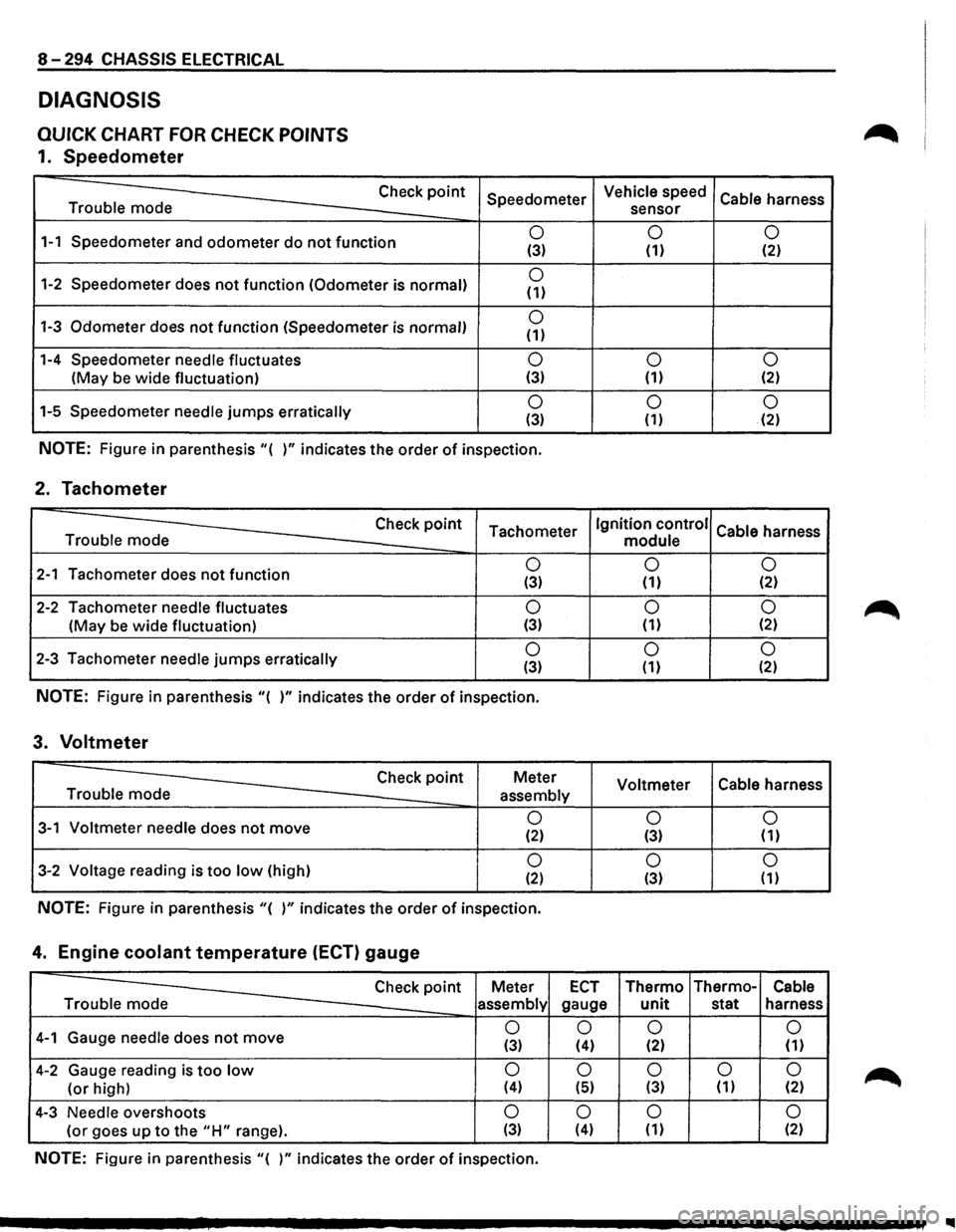
8-294 CHASSIS ELECTRICAL
DIAGNOSIS
QUICK CHART FOR CHECK POINTS
1. Speedometer
Trouble mode Check
point
1-1 Speedometer
and odometer do not function
1-2 Speedometer does not function (Odometer is normal)
1-3 Odometer does not function (Speedometer is normal)
1-4 Speedometer needle fluctuates
(May be wide fluctuation)
1-5 Speedometer
needle jumps erratically Speedometer
0 (3)
0 (1)
0 (1)
0 (3)
0 (3)
NOTE: Figure
in parenthesis "( )" indicates the order of inspection.
2. Tachometer
Check point Tachometer Trouble mode
2-1 Tachometer does not function 0 (3)
2-2 Tachometer needle fluctuates 0
(May be wide fluctuation) (3)
2-3 Tachometer needle jumps erratically 0 (3)
NOTE: Figure in parenthesis "( )" indicates the order of inspection.
3. Voltmeter
Check point Meter
Trouble mode
assembly
3-1 Voltmeter needle does not move 0 (2)
3-2 Voltage reading is too low (high) 0 (2)
NOTE: Figure in parenthesis "( )" indicates the order of inspection.
4. Engine coolant temperature (ECT) gauge
Vehicle speed
Cable harness
sensor
0 0 (1) (2)
0
0 (1) (2)
0 0 (1) (2)
Ignition control
Cable harness
module
0 0
(1) (2)
0 0 (1) {2)
0 0 (1) (2)
Voltmeter Cable
harness
0 0 (3) (1)
0
0 (3) (1)
Check point Meter ECT Thermo Thermo-Cable
Trouble mode
assembly gauge unit stat harness
4-1 Gauge needle does not move 0
0 0
0
(3) (4) (2) (1)
4-2 Gauge reading is too low 0 0 0 0 0
(or high) (4) (5) (3) (1) (2)
4-3 Needle overshoots 0 0 0 0
(or goes up to the "H" range). (3) (4) (1) (2)
NOTE: Figure in parenthesis "( )" indicates the order of inspection.
..
Page 1486 of 1928
8-296 CHASSIS ELECTRICAL
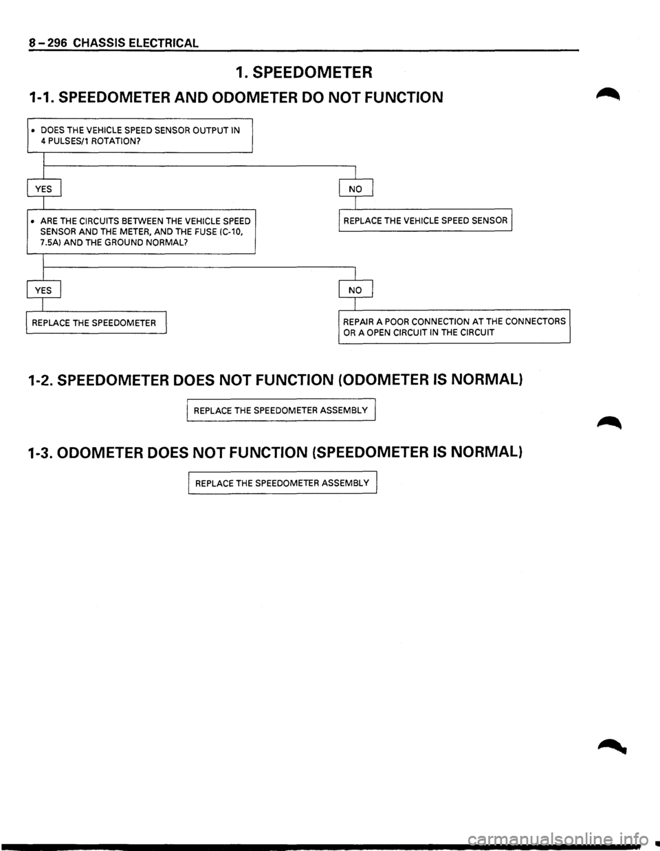
1. SPEEDOMETER
1-1. SPEEDOMETER AND ODOMETER DO NOT FUNCTION
• DOES THE VEHICLE SPEED SENSOR OUTPUT IN
4 PULSES/1 ROTATION?
I
I I
YES I NO I
I
I
• ARE
THE CIRCUITS BETWEEN THE VEHICLE SPEED REPLACE
THE VEHICLE SPEED SENSOR I
SENSOR AND THE METER, AND THE FUSE (C-10,
7.5A) AND THE GROUND NORMAL?
I
j I
YES I NO I
I I
REPLACE
THE SPEEDOMETER I REPAIR A POOR CONNECTION AT THE CONNECTORS
OR A OPEN CIRCUIT IN THE CIRCUIT
1-2. SPEEDOMETER DOES NOT FUNCTION (ODOMETER IS NORMAL)
I REPLACE THE SPEEDOMETER ASSEMBLY I
1-3. ODOMETER DOES NOT FUNCTION (SPEEDOMETER IS NORMAL)
I REPLACE THE SPEEDOMETER ASSEMBLy I
..
Page 1487 of 1928
CHASSIS ELECTRICAL 8-297
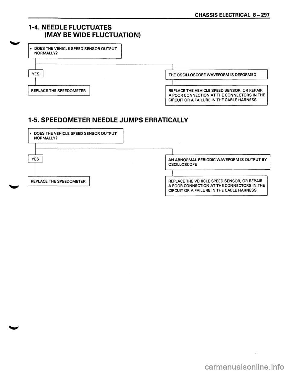
1-4. NEEDLE FLUCTUATES
(MAY
BE WIDE FLUCTUATION)
• DOES THE VEHICLE SPEED SENSOR OUTPUT
NORMALLY?
I
I
l
YES ~ THE OSCILLOSCOPE WAVEFORM IS DEFORMED
I r
REPLACE THE SPEEDOMETER I REPLACE THE VEHICLE SPEED SENSOR, OR REPAIR
A POOR CONNECTION AT THE CONNECTORS IN THE
CIRCUIT OR A FAILURE IN THE CABLE HARNESS
1-5. SPEEDOMETER NEEDLE JUMPS ERRATICALLY
• DOES THE VEHICLE SPEED SENSOR OUTPUT
NORMALLY?
I
YES I AN ABNORMAL PERIODIC WAVEFORM IS OUTPUT BY
OSCILLOSCOPE
I
REPLACE THE SPEEDOMETER I REPLACE THE VEHICLE SPEED SENSOR, OR REPAIR A POOR CONNECTION AT THE CONNECTORS IN THE CIRCUIT OR A FAILURE IN THE CABLE HARNESS
Page 1508 of 1928
8-318 CHASSIS ELECTRICAL
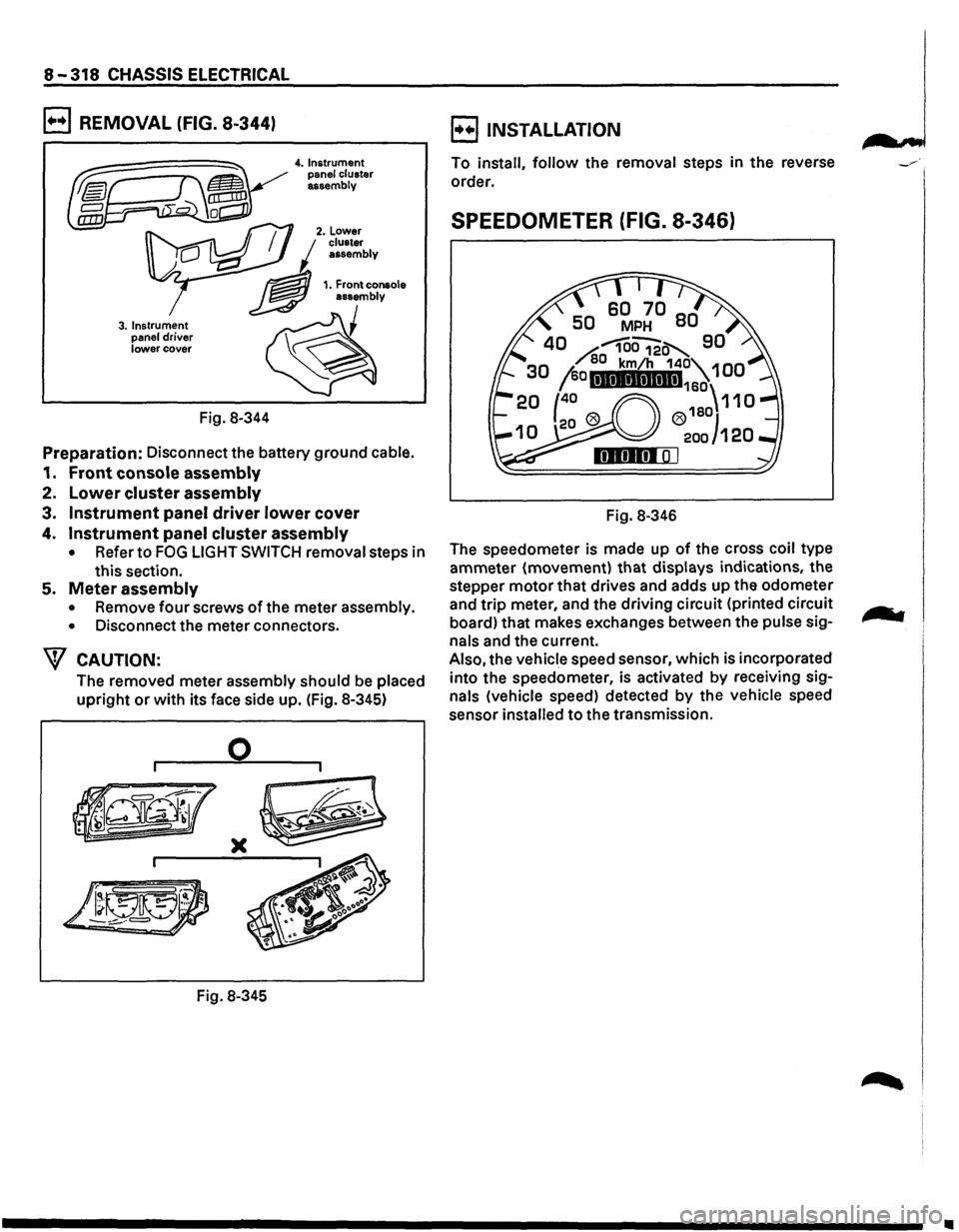
B REMOVAL (FIG. 8-344)
3. Instrument
panel driver lower cover
Fig. 8-344
4. Instrument
panel cluster
assembly
Preparation: Disconnect the battery ground cable.
1. Front console assembly
2. Lower cluster assembly
3. Instrument panel driver lower cover
4. Instrument panel cluster assembly
• Refer to FOG LIGHT SWITCH removal steps in
this section.
5. Meter assembly
• Remove four screws of the meter assembly.
•
Disconnect the meter connectors.
W CAUTION:
The removed meter assembly should be placed
upright or with its face side up. (Fig. 8-345)
0
)(
Fig. 8-345
B INSTALLATION
To install, follow the removal steps in the reverse
order.
SPEEDOMETER (FIG. 8-346)
Fig. 8-346
The speedometer is made up
of the cross coil type
ammeter (movement)
that displays indications, the
stepper
motor that drives and adds up the odometer
and
trip meter, and the driving circuit (printed circuit
board) that makes exchanges between the
pulse sig
nals and the current.
Also, the vehicle speed sensor, which is incorporated
into the speedometer, is activated
by receiving sig
nals (vehicle speed) detected by the vehicle speed
sensor
installed to the transmission.
•
Page 1510 of 1928
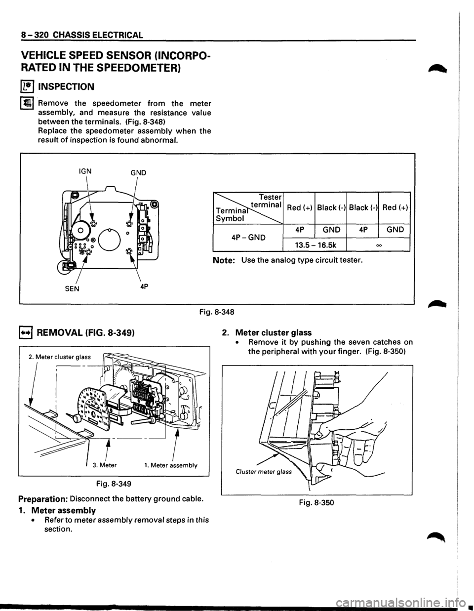
8-320 CHASSIS ELECTRICAL
VEHICLE SPEED SENSOR (INCORPO
RATED IN THE SPEEDOMETER)
~ INSPECTION
I tml Remove the speedometer from the meter
assembly, and measure the resistance value
between the terminals. (Fig. 8-348)
Replace the speedometer assembly
when the
result
of inspection is found abnormal.
IGN GND
SEN
Red(+) Black(-) Black(-) Red(+)
4P GND 4P GND
4P-GND 13.5-16.5k 00
Note: Use the analog type circuit tester.
Fig. 8-348
B REMOVAL (FIG. 8-349)
Fig. 8-349
Preparation: Disconnect the battery ground cable.
1.
Meter assembly
• Refer to meter assembly removal steps in this
section. 2.
Meter cluster glass
• Remove it by
pushing the seven catches on
the peripheral
with your finger. (Fig. 8-350)
Fig. 8-350
•
Page 1518 of 1928
8-328 CHASSIS ELECTRICAL
A/T INDICATOR LIGHT BULB
B REMOVAL
Preparation: Disconnect the battery ground cable.
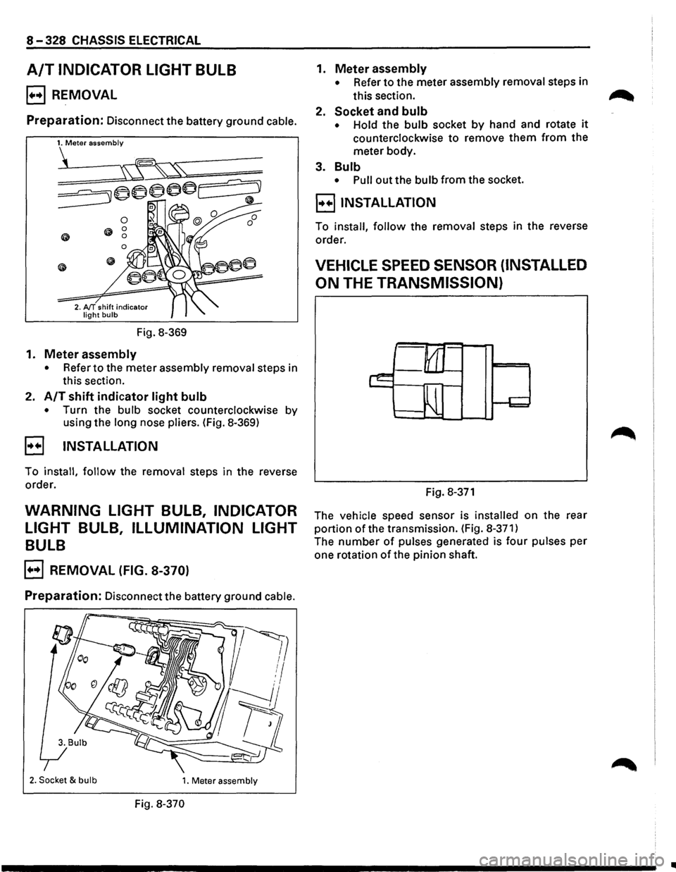
Fig.
8-369
1. Meter assembly
• Refer to the meter assembly removal steps in
this section.
2.
A/T shift indicator light bulb
• Turn the bulb socket counterclockwise by
using the
long nose pliers. (Fig. 8-369)
B INSTALLATION
To install, follow the removal steps in the reverse
order.
WARNING LIGHT BULB, INDICATOR
LIGHT
BULB, ILLUMINATION LIGHT
BULB
B REMOVAL (FIG. 8-370)
Preparation: Disconnect the battery ground cable.
2. Socket & bulb 1. Meter assembly
Fig. 8-370
1. Meter assembly
• Refer to the meter assembly removal steps in
this section.
2.
Socket and bulb
• Hold the bulb socket by hand and rotate it
counterclockwise to remove them from the
meter body.
3.
Bulb
• Pull out the bulb from the socket.
B INSTALLATION
To install, follow the removal steps in the reverse
order.
VEHICLE SPEED SENSOR (INSTALLED
ON
THE TRANSMISSION)
Fig. 8-371
The vehicle speed sensor is installed on the rear
portion of the transmission. (Fig. 8-371)
The number of pulses generated is four pulses per
one rotation
of the pinion shaft.
..