transmission ISUZU TROOPER 1995 Owner's Manual
[x] Cancel search | Manufacturer: ISUZU, Model Year: 1995, Model line: TROOPER, Model: ISUZU TROOPER 1995Pages: 1928
Page 245 of 1928
REAR AXLE 48-3
DIAGNOSIS OF REAR AXLE NOISE
Many noises that seem to come from the rear axle
actually
originate from other sources such as tires,
road surface, wheel bearings, engine, transmission,
muffler,
or body drumming. Investigate to find the
source
ofthe noise before disassembling the rear axle.
Rear axles,
like any other mechanical device, are not
absolutely quiet but should be considered quiet unless
some abnormal noise is present.
To make a systematic check
for axle noise, observe the
following:
1. Select a level asphalt road to reduce tire noise and
body drumming.
2. Check rear axle lubricant level to assure correct
level, and then drive the vehicle far enough to
thoroughly warm up the rear axle lubricant.
3. Note the speed at which noise occurs. Stop the
vehicle and put the transmission in neutral. Run
the engine speed
slowly up and down to
determine if the noise is caused by exhaust,
muffler noise, or other engine conditions.
4. Tire noise changes with different road surfaces;
axle noises do not. Temporarily inflate all tires to
344
kPa (50 psi) (for test purposes only). This will
change noise caused by tires but will not affect
noise caused by the rear
axle.
Rear axle nose usually stops when coasting at
speeds under
48 km/h (30 mph); however, tire
noise continues
with a lower tone. Rear axle noise
usually changes when comparing pull and coast,
but tire noise stays about the same.
Distinguish between tire noise and rear
axle noise
by noting
if the noise changes with various
speeds
or sudden acceleration and deceleration.
Exhaust and
axle noise vary under these
conditions,
while tire noise remains constant and
is more pronounced at speeds
of 32 to 48 km/h
(20 to 30 mph). Further check for tire noise by
driving the vehicle
over smooth pavements or dirt
roads (not gravel) with the tires at normal
pressure.
If the noise is caused by tires, it will
change noticeably with changes in road surface.
5. Loose or rough front wheel bearings will cause
noise
which may be confused with rear axle
noise; however, front wheel bearing noise does
not change when comparing drive and coast.
Light application
of the brake while holding
vehicle speed steady
will often cause wheel
bearing noise to diminish. Front wheel bearings
may be checked for noise by jacking up the
wheels and spinning them
or by shaking the
wheels
to determine if bearings are loose.
6. Rear suspension rubber bushings and spring
insulators dampen
out rear axle noise when
correctly installed. Check to see that there is no
link or rod loosened or metal-to-metal contact.
7. Make sure that there is no metal-to-metal contact
between the
floor and the frame.
After the noise has been determined to be in the axle,
the type of axle noise should be determined, in order to
make any necessary repairs.
GEAR NOISE
Gear noise (whine) is audible from 32 to 89 km/h (20 to
55 mph) under four driving conditions.
1. In drive under acceleration or heavy pull.
2. Driving under load or under constant speed.
3. When using enough throttle to keep the vehicle
from driving the engine while the vehicle slows
down gradually (engine still pulls slightly).
4. When coasting with the vehicle in gear and the
throttle closed. The gear noise is
usually more
noticeable between 48 and 64
km/h (30 and 40
mph) and 80 and 89 km/h (50 and 55 mph).
BEARING NOISE
Bad bearings generally produce a rough growl or
grating sound, rather than the whine typical of gear
noise. Bearing noise frequently
"wow-wows" at
bearing rpm, indicating a bad pinion
or rear axle side
bearing. This noise can
be confused with rear wheel
bearing noise.
REAR WHEEL BEARING NOISE
Rear wheel bearing noise continues to be heard while
coasting at low speed with transmission in the neutral.
Noise may diminish by gentle braking. Jack up the rear
wheels, spin them by hand and
listen for noise at the
hubs. Replace any faulty
wheel bearings.
KNOCK AT LOW SPEEDS
Low speed knock can be caused by worn universal
joints or a side gear hub counter bore in the cage that is
worn oversize. Inspect and replace universal joints or
cage and side gears as required.
BACKLASH CLUNK
Excessive clunk on acceleration and deceleration can
be caused by a worn rear axle pinion shaft, a worn
cage, excessive clearance between the axle and the
side gear splines, excessive clearance between the
side gear hub and the counterbore in the cage,
worn
pinion and side gear teeth, worn thrust washers, or
excessive drive pinion and ring gear backlash.
Remove
worn parts and replace as required. Select
close-fitting parts when possible. Adjust pinion and
ring gear backlash.
Page 322 of 1928
SA-2 HYDRAULIC BRAKES
BRAKE SYSTEM DIAGNOSIS
ROAD TESTING THE BRAKES
Brake Test
Brakes should be tested on a dry, clean, reasonably
smooth and
level roadway. A true test of brake
performance cannot be made
if the roadway is
wet, greasy
or covered with loose dirt so that all
tires do not grip the road equally. Testing will also
be adversely affected if the roadway is crowned so
as to throw the weight of the vehicle toward
wheels on one side or if the roadway is so rough
that wheels tend to bounce. Test the brakes at dif
ferent vehicle speeds with both light and heavy
pedal pressure; however, avoid locking the wheels
and sliding the tires. Locked wheels and sliding
tires do not indicate brake efficiency, since heavily
braked but turning wheels will stop the vehicle in
less distance than locked wheels. More tire-to-road
friction is present
with a heavily braked turning tire
then
with a sliding tire.
The standard brake system is designed and
balanced
to avoid locking the wheels except at very high
deceleration
levels.
It
is designed this way because the shortest stopping
distance and best
control is achieved without brake
lock-up.
Because of high deceleration capability, a firmer pedal
may be felt at higher deceleration levels.
External Conditions That Affect Brake
Performance
1.
2.
3.
Tires: Tires having unequal contact and grip on
the road
will cause unequal braking. Tires must
be equally inflated, identical in size, and the tread
pattern
of right and left tires must be approxi
mately equal.
Vehicle loading:
A heavily loaded vehicle requires
more braking effort.
Wheel Alignment: Misalignment of the wheels,
particularly
in regard to excessive camber and
caster,
will cause the brakes to pull to one side.
BRAKE FLUID LEAKS
With engine running at idle and the transmission in
"Neutral", depress the brake pedal and hold a constant
foot pressure on the pedal. If pedal gradually falls
away with the constant pressure, the hydraulic system
may be leaking.
Check the master cylinder fluid level. While a slight
drop in reservoir level will result from normal lining
wear, an abnormally low level in reservoir indicates a
leak in the system. The hydraulic system may be
leaking internally as well as externally. Refer to
"Master Cylinder Inspection". Also, the system may
appear
to pass this test but still have slight leakage. If
fluid level
is normal, check the vacuum booster
push rod
length. If an incorrect length push rod is
found, adjust
or replace the push rod. Check the
brake
pedal travel and the parking brake adjust
ment.
When checking the
fluid level, the master cylinder fluid
level
may be low from the "MAX" mark if the front and
rear
linings are worn. This is not abnormal.
WARNING LIGHT OPERATION
When the ignition switch is in the START position,
the
"BRAKE" warning light should glow and go off
when the ignition switch returns to the ON position.
The
following conditions will activate the "BRAKE"
light:
1. Parking brake applied. The light should be on
whenever the parking brake is applied and the
ignition switch is on.
2. Low fluid level. A low fluid level in the master
cylinder will turn the "BRAKE" light on (Except
Rear
Wheel Antilock Brake System (RWAL)
model).
3. During engine cranking the "BRAKE" light
should
remain on. This notifies the driver that
the warning circuit is operating properly.
4. In the event of a front or rear system malfunc
tion (RWAL model only).
5. In the event of RWAL malfunction (RWAL
model only. Refer to Section 5A3).
ANTILOCK BRAKE SYSTEM (RWAL or
ABS}
Refer to Section 5A3 or 5A4 for inspection and di
agnosis procedure of the hydraulic unit.
..
Page 411 of 1928
4-WHEEL ANTILOCK BRAKE SYSTEM (ABS) 5A4-1
SECTION 5A4
'--' 4-WHEEL ANTILOCK BRAKE SYSTEM (ABS)
CAUTION
All
brake attaching fasteners are an important attaching part in that they could affect performance of
vital parts and systems, and/or could result in major repair expense. They must be replaced with one
of the same part number or with an equivalent part if replacement becomes necessary. Do not use
replacement parts
of lesser quality or substitute design. Torque values must be used as specified
during reassembly to assure proper retention of these parts.
CONTENTS
General Description .................... 5A4-3
System Components ................. 5A4-3
Electronic Brake
Control Module ·
(EBCM) .......................... 5A4-3
Hydraulic Unit ...................... 5A4-3
ABS Warning Light .................. 5A4-4
Wheel
Speed Sensor ................. 5A4-4
G-Sensor
........................... 5A4-4
Normal and Antilock Braking .......... 5A4-4
Brake Pedal Travel
................... 5A4-4
Abbreviation ........................ 5A4-4
Diagnosis
............................. 5A4-5
General
Information ................. 5A4-5
ABS
System Service Precautions ....... 5A4-5
Computer System Service
Precautions
....................... 5A4-5
General Service Precautions
........... 5A4-5
Note on lntermittents ................ 5A4-6
Test Driving ABS Complaint Vehicles ... 5A4-6
II ABS11 Warning Light ................ 5A4-6
Normal Operation ................... 5A4-6
Basic
Diagnostic Flow Chart ........... 5A4-7
Basic
Inspection Procedure ............ 5A4-8
TECH 1
TOOL. ......................... 5A4-10
1. What can be done with TECH 1 ...... 5A4-10
2. How to Use TECH 1 ................ 5A4-11
3. Explanation of Modes .............. 5A4-15
Mode FO: Data List ................... 5A4-16
Mode F2: Trouble Code ............... 5A4-18
Mode F3: Snapshot .................. 5A4-19
Mode F4: Clear Code ................. 5A4-20
Mode F5: Actuator Test ............... 5A4-21
Mode F6: Wheel Sensors ............. 5A4-31
Pin-Out Checks ........................ 5A4-33
Circuit Diagram ..................... 5A4-34
Part Location ....................... 5A4-37
Symptom Diagnosis .................... 5A4-38
CHART A-1 1) ABS Works Frequently
but Vehicle does not Decelerate ...... 5A4-39
CHART TA-1 1) ABS Works Frequently
but Vehicle does not Decelerate ...... 5A4-40
CHART A-2 2) Uneven Braking Occurs
while ABS Works .................. 5A4-41
CHART TA-2 2) Uneven Braking Occurs
while ABS Works .................. 5A4-42
CHART A-3, T A-3 3) The Wheels are
Locked
........................... 5A4-43
CHART A-4 4) Brake Pedal Feel is
Abnormal ........................ 5A4-44
CHART A-5 , T A-5 5) Braking Sound
(from Hydraulic Unit) is Heard while
not Braking ....................... 5A4-45
Diagnosis by 11 ABS11 Warning Light
Illumination Pattern .................. 5A4-46
Diagnostic Trouble Codes (DTCs) ....... 5A4-47
1. How to Display and Erase DTCs ... 5A4-47
2. Diagnostic Trouble Codes ........ 5A4-49
CHART B-1 With the Key in the ON
Position (before Starting the Engine),
Warning Light (W /L) is not
•
Actuated ........................ 5A4-50
CHART B-2 II ABSII Light Flashes
Twice with Key ON ................ 5A4-51
CHART B-3 EBCM Abnormality (Diagnostic
Trouble Code 14) .................. 5A4-52
CHART B-4 Power Voltage Drop (Diagnostic
Trouble Code 15) .................. 5A4-53
CHART B-5 G-Sensor Circuit (Diagnostic
Trouble Code 21) .................. 5A4-54
CHART B-6 Brake Switch Trouble
(Diagnostic Trouble Code 22) ........ 5A4-55
CHART B-7 Abnormal Transmission Input
(A/T Modei)(Diagnostic Trouble
Code 23) ......................... 5A4-56
CHART B-7 Abnormal Transmission Input
(M/T Modei)(Diagnostic Trouble
Code 23) ......................... 5A4-57
CHART B-8 Hydraulic Unit (HU) Pump
Motor and Motor Relay Circuit
(Diagnostic Trouble Code 32) ........ 5A4-58
CHART B-9 Solenoid Valve Abnormality
(Diagnostic Trouble Code 41, 42,
& 44) ............................ 5A4-59
CHART B-10 Valve Relay Abnormality
(Diagnostic Trouble Code 45) ........ 5A4-60
Page 412 of 1928
5A4-2 4-WHEEL ANTILOCK BRAKE SYSTEM (ABS)
CHART B-11 Speed Sensor Disconnection
(Diagnostic
Trouble Code
51, 52, 53, & 54) ................... 5A4-61
CHART B-12 Speed Sensor Short Circuit
(Diagnostic Trouble Code
61, 62,
63,
& 64) ................... 5A4-62
CHART B-13, TB-13 Sensor Signal Input
Abnormality (Diagnostic Trouble
Code
65) ......................... 5A4-63
Unit Inspection Procedure ............... 5A4-64
CHART C-1 G-Sensor Unit Inspection
Procedure ........................ 5A4-65
CHART C-2 Sensor Output Inspection
Procedure ........................ 5A4-66
CHART TC-2 Sensor Output Inspection
Procedure ........................ 5A4-67
CHART C-3 4WD Switch Inspection
Procedure ........................ 5A4-68
CHART TC-3 4WD Switch Inspection
Procedure ........................ 5A4-69
CHART C-4 Transmission Input
Inspection Procedure (A/T Modell .... 5A4-70
CHART C-4 Transmission Input
Inspection Procedure (M/T Model) .... 5A4-71
CHART TC-4 Transmission Input
Inspection Procedure ............... 5A4-72
On-Vehicle Service ..................... 5A4-73
Hydraulic Unit ...................... 5A4-73
Electronic Brake Control Module
(EBCMI .......................... 5A4-74
G-Sensor ........................... 5A4-75
Front Wheel Speed Sensor ............ 5A4-76
Rear
Wheel Speed Sensor ............ 5A4-78
Special Tools .......................... 5A4-79
..
Page 417 of 1928
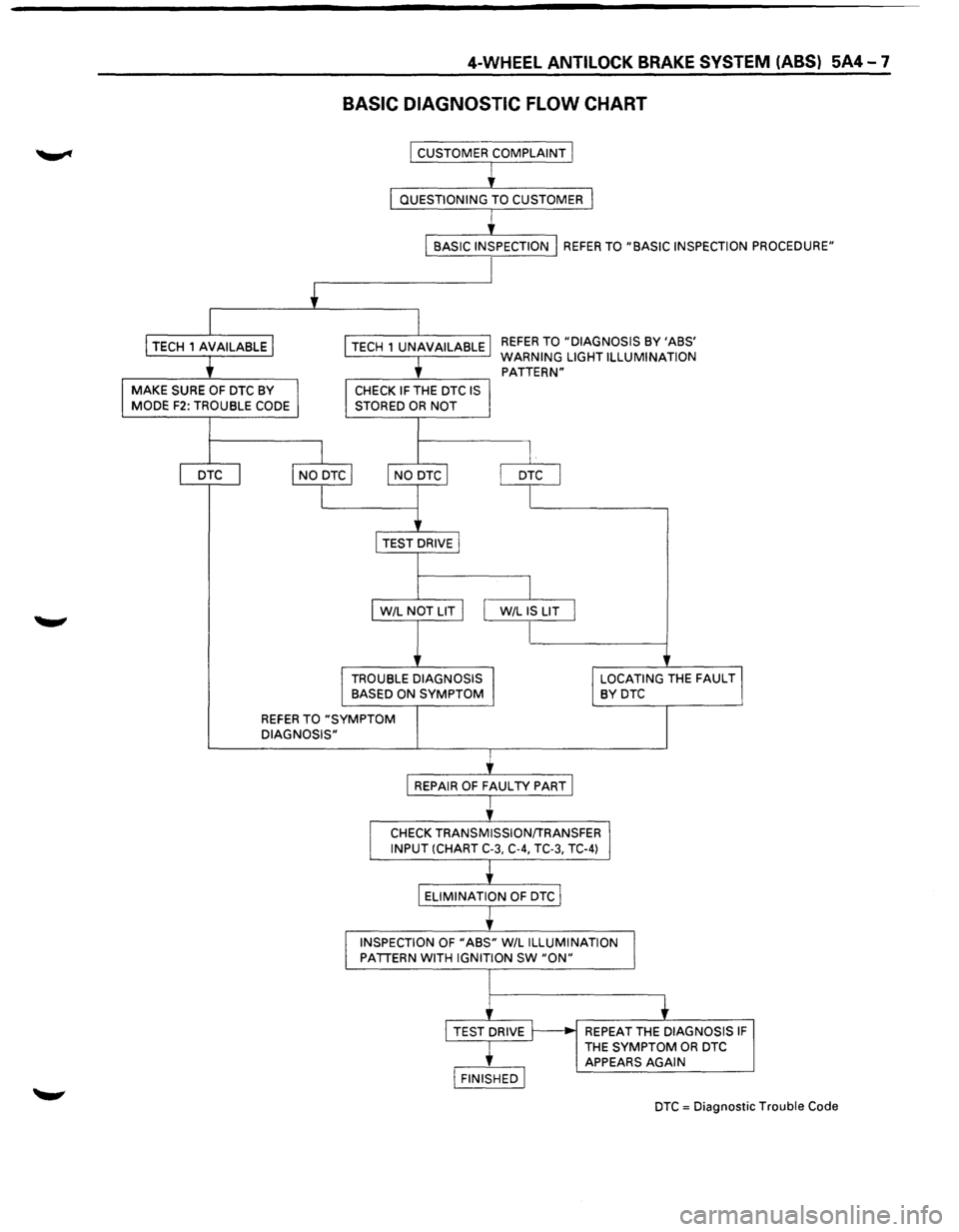
4-WHEEL ANTILOCK BRAKE SYSTEM (ABS) 5A4-7
BASIC DIAGNOSTIC FLOW CHART
I CUSTOMER COMPLAINT I
I
' I QUESTIONING TO CUSTOMER 1
I
BASIC INSPECTION I REFER TO "BASIC INSPECTION PROCEDURE"
+
I
I TECH 1 AVAILABLE I
I TECH 1 UNAVAILABLE REFER TO "DIAGNOSIS BY 'ABS'
t
WARNING LIGHT ILLUMINATION
PATTERN"
I MAKE SURE OF DTC BY I MODE F2: TROUBLE CODE I CHECK IF THE DTC IS STORED OR NOT
I I
I DTC I I NO DTC I I NO
DTC I
I DTC I
I I
I TEST
DRIVEl
I
I W/L NOT LIT I I W/L IS LIT I
I
I TROUBLE DIAGNOSIS I BASED ON SYMPTOM I LOCATING THE FAUL Tj BYDTC
REFER TO "SYMPTOM
DIAGNOSIS"
I REPAIR OF FAUL TV PART I
I
CHECK TRANSMISSION/TRANSFER~ INPUT (CHART C-3, C-4, TC-3, TC-4)
ELIMINATION
OF DTC I
I
INSPECTION OF "ABS" W/L ILLUMINATION
1 PATTERN WITH IGNITION SW "ON"
+ I TEST DRIVE ~ REPEAT THE DIAGNOSIS IF
THE SYMPTOM OR DTC
APPEARS AGAIN
I FINISHED I
DTC = Diagnostic Trouble Code
Page 420 of 1928
5A4-10 4-WHEEL ANTILOCK BRAKE SYSTEM (ABS)
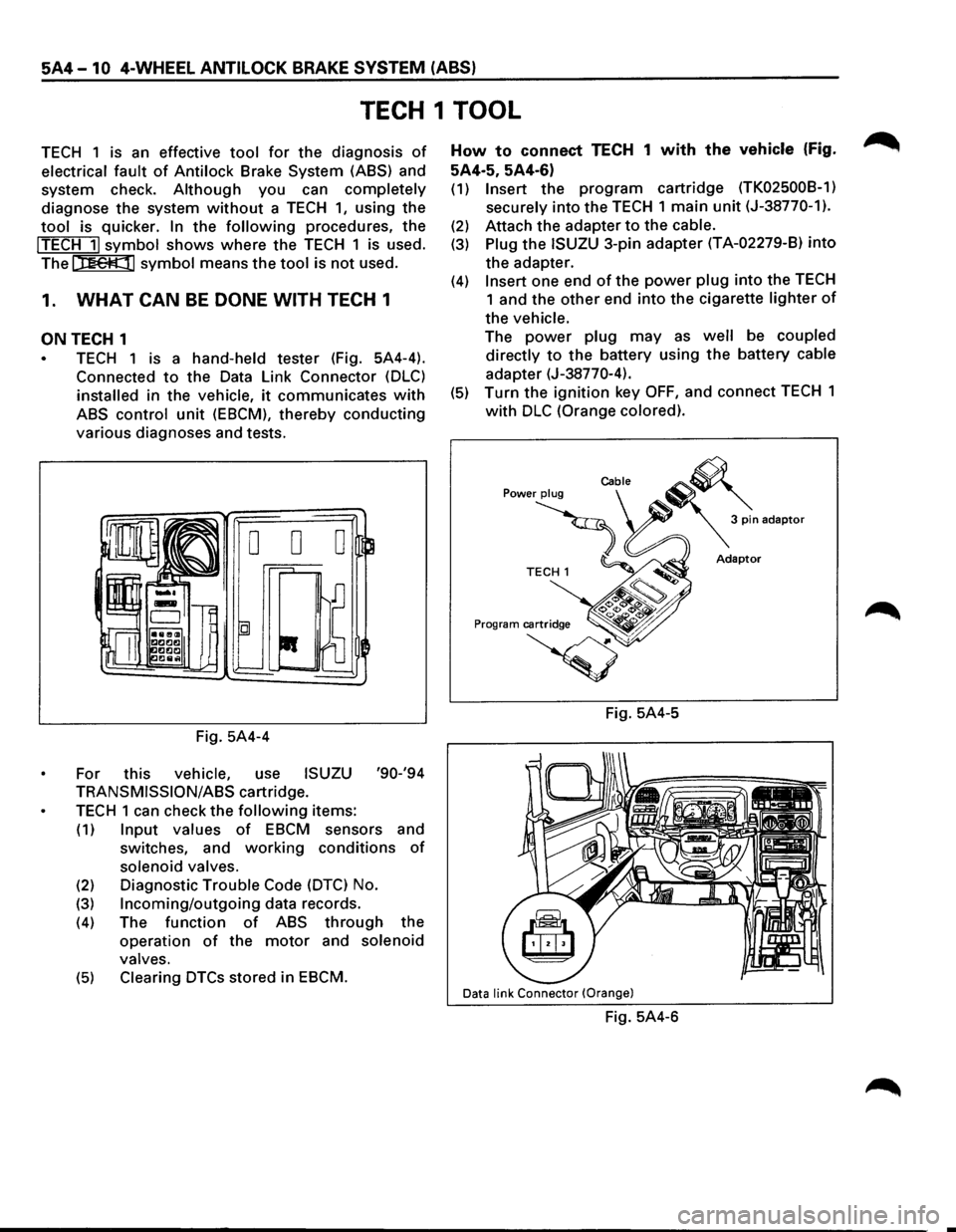
TECH 1 TOOL
TECH 1 is an effective tool for the diagnosis of
electrical fault of Antilock Brake System (ASS) and
system check.
Although you can completely
diagnose the system without a TECH 1, using the
tool is quicker. In the following procedures, the
!TECH 11 symbol shows where the TECH 1 is used.
The
t::nettll symbol means the tool is not used.
1. WHAT CAN BE DONE WITH TECH 1
ON TECH 1
TECH 1 is a hand-held tester (Fig. 5A4-4).
Connected
to the Data Link Connector (DLC)
installed in the vehicle, it communicates with
ABS control unit (EBCM), thereby conducting
various diagnoses and tests.
Fig. 5A4-4
For this
vehicle, use ISUZU '90-'94
TRANSMISSION/ASS cartridge.
TECH 1 can check the following items:
(1) Input values of EBCM sensors and
switches, and
working conditions of
solenoid valves.
(2) Diagnostic Trouble Code (DTC) No.
(3) Incoming/outgoing data records.
(4) The function of ABS through the
operation
of the motor and solenoid
valves.
(5) Clearing DTCs stored in EBCM.
How to connect TECH 1 with the vehicle (Fig.
5A4·5, 5A4-6)
(1) Insert the program cartridge (TK02500B-1)
securely
into the TECH 1 main unit (J-38770-1).
(2) Attach the adapter to the cable.
(3) Plug the ISUZU 3-pin adapter (T A-02279-8) into
the adapter.
(4) Insert one end of the power plug into the TECH
1 and the other end into the cigarette lighter of
the vehicle.
The power plug may as well be coupled
directly
to the battery using the battery cable
adapter (J-38770-4).
(5) Turn the ignition key OFF, and connect TECH 1
with DLC (Orange colored).
Fig. 5A4-5
Data link Connector (Orange)
Fig. 5A4-6
Page 421 of 1928
4-WHEEL ANTILOCK BRAKE SYSTEM (ABS) 5A4-11
2. HOW TO USE TECH 1
Operating procedure for TECH 1
After connecting with the vehicle, turn the ignition
key
ON and follow the flow chart.
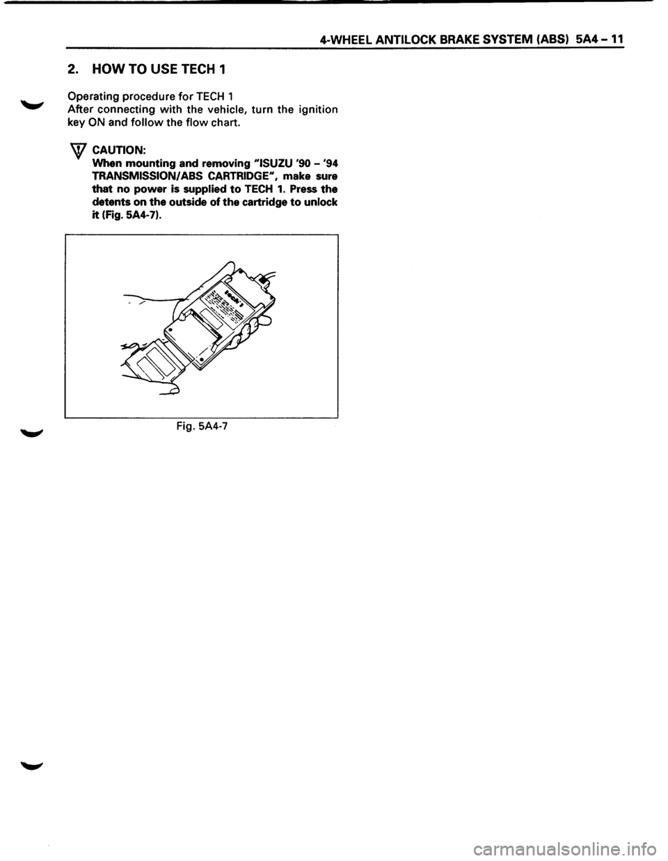
W CAUTION:
When mounting and removing "ISUZU '90 -'94
TRANSMISSION/ ABS CARTRIDGE", make sure
that no power is supplied to TECH 1. Press the
detents on the outside of the cartridge to unlock
it (Fig. 5A4-7).
Fig. 5A4-7
Page 422 of 1928
5A4-12 4-WHEEL ANTILOCK BRAKE SYSTEM (ABS)
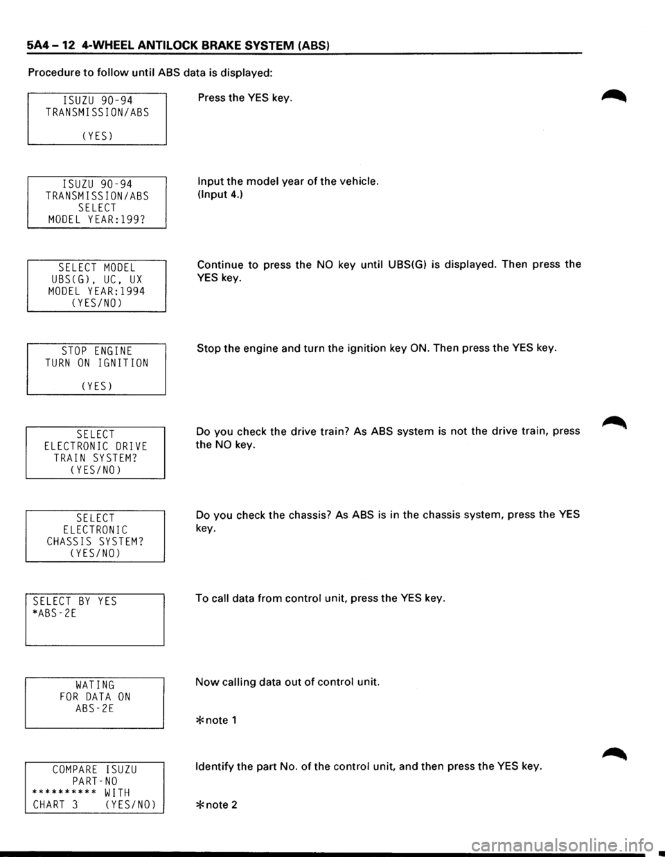
Procedure to follow until ABS data is displayed:
ISUZU 90-94
TRANSMISSION/ASS
C YES)
ISUZU 90-94
TRANSMISSION/ASS
SELECT
MODEL YEAR:l99?
SELECT MODEL
UBSCG), UC, UX
MODEL YEAR:l994
CYES/NO)
STOP ENGINE
TURN ON IGNITION
C YES)
SELECT
ELECTRONIC DRIVE
TRAIN SYSTEM?
CYES/NO)
SELECT
ELECTRONIC
CHASSIS SYSTEM?
CYES/NO)
SELECT BY YES
*ABS-2E
WATING
FOR DATA ON
ABS-2E
COMPARE ISUZU
PART-NO
********** WITH
CHART 3 CYES/NO)
Press the YES key.
Input the model year of the vehicle.
(Input
4.)
Continue to press the NO key until UBS(G) is displayed. Then press the
YES key.
Stop the engine and turn the ignition key
ON. Then press the YES key.
Do you check the drive train? As ABS system is
not the drive train, press
the
NO key.
Do you check the chassis? As ABS
is in the chassis system, press the YES
key.
To
call data from control unit, press the YES key.
Now calling data out of control unit.
Identify the part No. of the control unit, and then press the YES key.
Page 428 of 1928
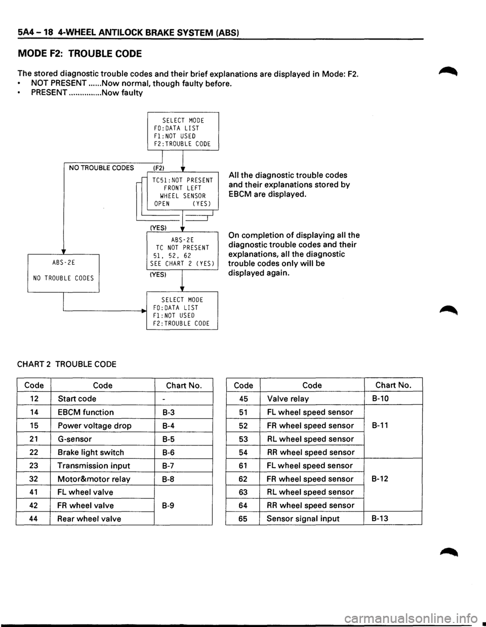
5A4-18 4-WHEEL ANTILOCK BRAKE SYSTEM (ABS)
MODE F2: TROUBLE CODE
The stored diagnostic trouble codes and their brief explanations are displayed in Mode: F2.
NOT PRESENT ...... Now normal, though faulty before.
PRESENT ............... Now faulty
NO TROUBLE CODES
ABS-2E
NO TROUBLE CODES
CHART 2 TROUBLE CODE
Code Code
12 Start code
14 EBCM function
15 Power voltage drop
21 G-sensor
22 Brake light switch
23 Transmission input
32 Motor&motor relay
41 FL wheel valve
42 FR wheel valve
44 Rear wheel valve
SELECT MODE FO:DATA LIST
F1: NOT USED F2:TROUBLE CODE
I
l (F2)
TC51:NOT PRESENT FRONT LEFT
WHEEL SENSOR OPEN (YESJ
(YES) J--_j
ABS-2E TC NOT PRESENT
51. 52, 62 SEE CHART 2 (YESJ
(YES)
l
SELECT MODE FO: DATA LIST
Fl:NOT USED F2:TROUBLE CODE
Chart No.
-
B-3
B-4
B-5
B-6
B-7
B-8
B-9
All the diagnostic trouble codes
and
their explanations stored by
EBCM are displayed.
On completion of displaying all the
diagnostic trouble codes and
their
explanations, all the diagnostic
trouble codes
only will be
displayed again.
Code Code
45 Valve relay
51 FL wheel speed sensor
52 FR wheel speed sensor
53 RL wheel speed sensor
54 RR wheel speed sensor
61 FL wheel speed sensor
62 FR wheel speed sensor
63 RL wheel speed sensor
64 RR wheel speed sensor
65 Sensor signal input
Chart No.
B-10
B-11
B-12
B-13
•
Page 429 of 1928
4-WHEEL ANTILOCK BRAKE SYSTEM (ABS) 5A4-19
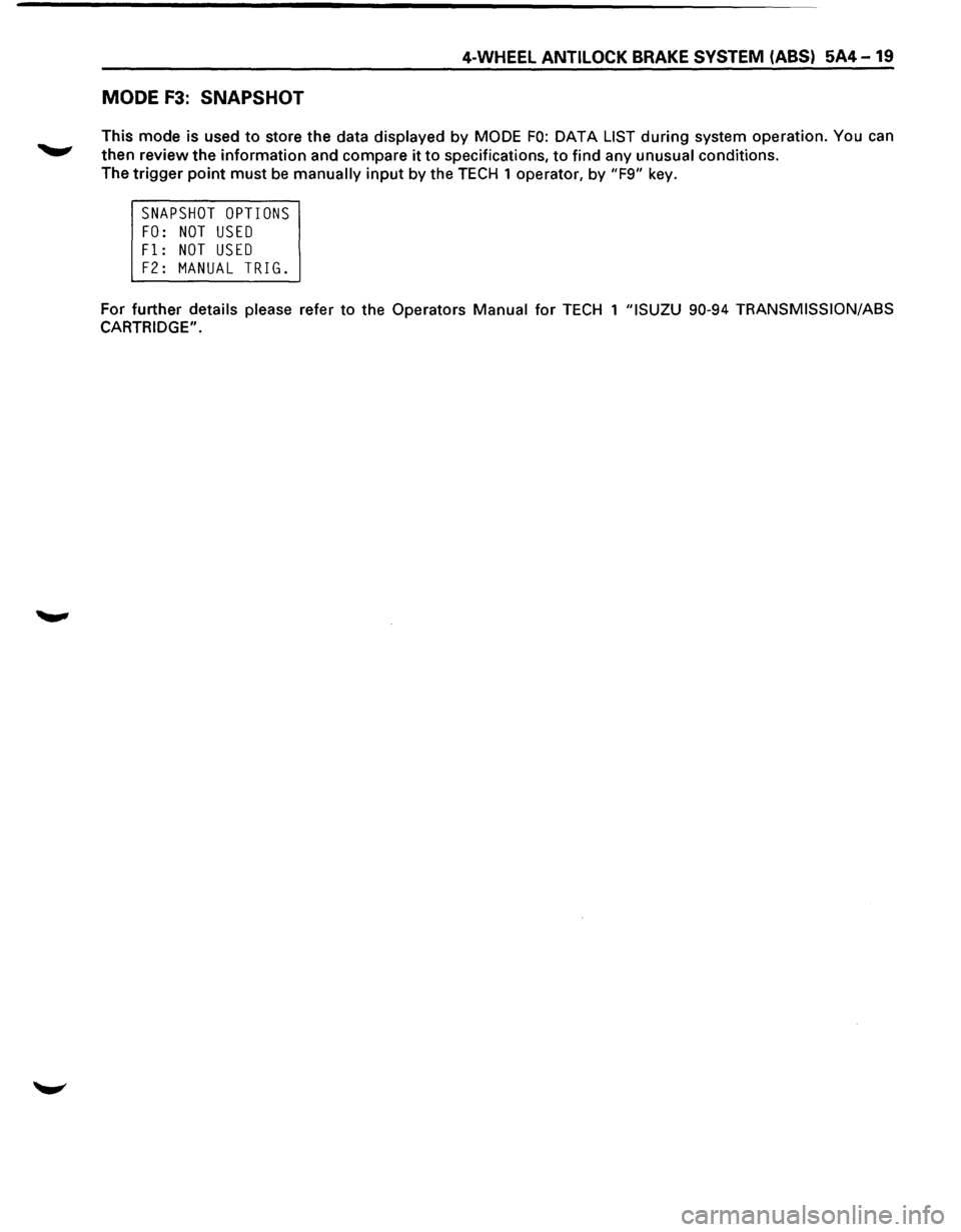
MODE F3: SNAPSHOT
This mode is used to store the data displayed by MODE FO: DATA LIST during system operation. You can
then review the information and compare it to specifications, to find any unusual conditions.
The
trigger point must be manually input by the TECH 1 operator, by "F9" key.
SNAPSHOT OPTIONS
FO: NOT USED
Fl: NOT USED
F2: MANUAL TRIG.
For further details please refer to the Operators Manual for TECH 1 "ISUZU 90-94 TRANSMISSION/ASS
CARTRIDGE".