transmission ISUZU TROOPER 1995 User Guide
[x] Cancel search | Manufacturer: ISUZU, Model Year: 1995, Model line: TROOPER, Model: ISUZU TROOPER 1995Pages: 1928
Page 25 of 1928
MAINTENANCE AND LUBRICATION 08-9
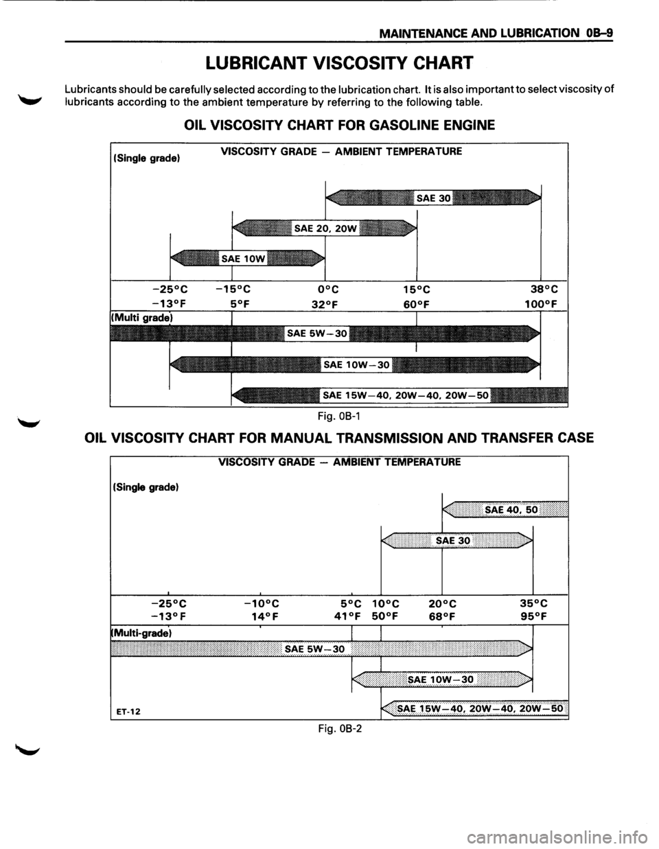
LUBRICANT VISCOSITY CHART
Lubricants should be carefully selected according to the lubrication chart. It is also important to select viscosity of
lubricants according to the ambient temperature by referring to the following table.
OIL VISCOSITY CHART FOR GASOLINE ENGINE
(Single grade) VISCOSITY GRADE -AMBIENT TEMPERATURE
Fig.
OB-1
OIL VISCOSITY CHART FOR MANUAL TRANSMISSION AND TRANSFER CASE
(Single grade)
Fig.
08-2
Page 29 of 1928
MAINTENANCE AND LUBRICATION OB-13
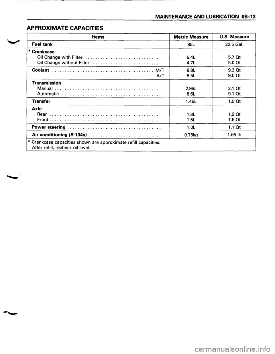
APPROXIMATE CAPACITIES
Items Metric Measure U.S. Measure
Fuel tank 85L 22.5 Gal.
*Crankcase
Oil Change with Filter .............................. 5.4L 5.7 at
Oil Change without Filter ••••••••••••••••••\
0 •••• 0 ••• 4.7L
5.0 at
Coolant ........................................ MIT 8.8L 9.3 at
A/T 8.5L 9.0 at
Transmission
Manual
.......................................... 2.95L 3.1 at
Automatic ••••••••••••••••••\
•• 0 •••• 0 0 0 ••••••••••• 8.6L 9.1 at
Transfer
1.45L 1.5 at
Axle
Rear o o o 0
0 0 0 0 0 0 0 0 0 0 0 0 0 0 0 0 I 0 0 0 o o o o o o o 0 0 0 0 0 0 0 0 0 0 0 o o 1.8L 1.9 at
Front ........................................ ~ ... 1.5L 1.6 at
Power steering ••• 0 ••••••••• 0 ••••••••••••••••••\
0 •••• 1.0L 1.1 at
Air conditioning (R-134a) o o 0
0 0 0 0 0 0 0 0 I 0 0 0 0 0 o o 0 o 0 0 0 0 0 0 0 0.75kg 1.651b
* Crankcase capacities shown are approximate refill capacities.
After
refill, recheck oil level.
Page 58 of 1928
1 B - 4 AIR CONDITIONING
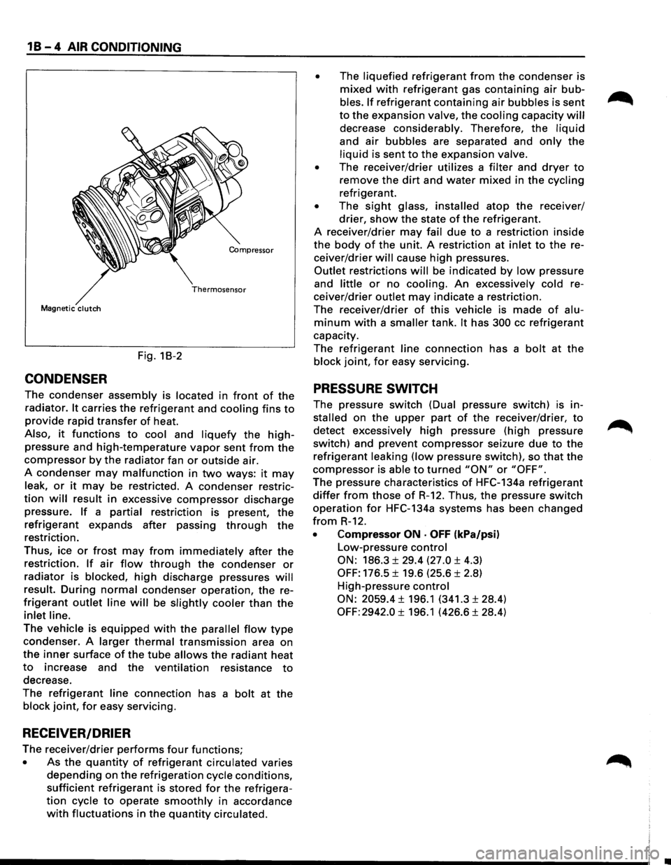
Compressor
Thermosensor
Magnetic clutch
Fig. 18-2
CONDENSER
The condenser assembly is located in front of the
radiator. It carries the refrigerant and cooling fins to
provide rapid transfer of heat.
Also, it functions to cool and liquefy the high
pressure and high-temperature vapor sent from the
compressor by the radiator fan or outside air.
A condenser
may malfunction in two ways: it may
leak, or it may be restricted. A condenser restric
tion will result in excessive compressor discharge
pressure.
If a partial restriction is present, the
refrigerant expands after passing through the
restriction.
Thus, ice
or frost may from immediately after the
restriction. If air flow through the condenser or
radiator is blocked, high discharge pressures will
result. During normal condenser operation, the re
frigerant outlet line will be slightly cooler than the
inlet line.
The vehicle is equipped with the parallel flow type
condenser. A larger thermal transmission area on
the inner surface of the tube allows the radiant heat
to increase and the ventilation resistance to
decrease.
The
refrigerant line connection has a bolt at the
block joint, for easy servicing.
RECEIVER/DRIER
The receiver/drier performs four functions;
• As the quantity of refrigerant circulated varies
depending on the refrigeration cycle conditions,
sufficient refrigerant is stored for the refrigera
tion cycle to operate smoothly in accordance
with fluctuations in the quantity circulated. •
The liquefied refrigerant from the condenser
is
mixed with refrigerant gas containing air bub
bles. If refrigerant containing air bubbles is sent
to the expansion valve, the cooling capacity will
decrease considerably. Therefore, the liquid
and air bubbles are separated and only the
liquid is sent to the expansion valve.
•
The receiver/drier utilizes a filter and dryer to
remove the dirt and water mixed in the cycling
refrigerant.
• The sight glass, installed atop the receiver/
drier, show the state of the refrigerant.
A receiver/drier may fail due to a restriction inside
the body of the unit. A restriction at inlet to the re
ceiver/drier
will cause high pressures.
Outlet restrictions will be indicated by low pressure
and
little or no cooling. An excessively cold re
ceiver/drier
outlet may indicate a restriction.
The receiver/drier
of this vehicle is made of alu
minum with a smaller tank. It has 300 cc refrigerant
capacity.
The
refrigerant line connection has a bolt at the
block joint, for easy servicing.
PRESSURE SWITCH
The pressure switch (Dual pressure switch) is in
stalled on the upper part of the receiver/drier, to
detect excessively high pressure (high pressure
switch) and prevent compressor seizure due to the
refrigerant leaking (low pressure switch), so that the
compressor is able to turned "ON" or "OFF".
The pressure characteristics of HFC-134a refrigerant
differ from those of R-12. Thus, the pressure switch
operation for HFC-134a systems has been changed
from R-12.
• Compressor ON · OFF (kPa/psi)
Low-pressure control
ON: 186.3 ± 29.4 (27.0 ± 4.3)
OFF: 176.5 ± 19.6 (25.6 ± 2.8)
High-pressure
control
ON: 2059.4 ± 196.1 (341.3 ± 28.4)
OFF: 2942.0 ± 196.1 (426.6 ± 28.4)
Page 217 of 1928
SUPPLEMENTAL RESTRAINT SYSTEM (SRS) STEERING WHEEL & COLUMN 3F4-7
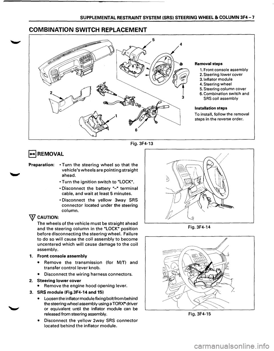
COMBINATION SWITCH REPLACEMENT
Fig. 3F4-13
E) REMOVAL
Preparation: • Turn the steering wheel so that the
vehicle's wheels are pointing straight
ahead.
W CAUTION: •
Turn the ignition switch to "LOCK".
•
Disconnect the battery "-" terminal
cable, and wait at least 5 minutes.
• Disconnect the yellow 3way SRS
connector located under the steering
column.
The wheels ofthe vehicle must be straight ahead
and
the steering column in the "LOCK" position
before disconnecting the steering wheel. Failure
to do so will cause the coil assembly to become
uncentered
which will cause damage to the coil
assembly.
1.
Front console assembly
•
Remove the transmission (for M{f) and
transfer control lever knob.
• Disconnect the wiring harness connectors.
2. Steering lower cover
• Remove the engine hood opening lever.
3. SRS module (Fig.3F4-14 and 15)
• Loosen the inflator module fixing bolt from behind
the steering
wheel assembly using a TORxe driver
or
equivalent until the inflator module can be
released from steering assembly.
•
Disconnect the yellow 2way SRS connector
located behind the inflator module.
3
Removal steps
1. Front console assembly
2. Steering lower cover
3.1nflator module
4. Steering wheel
5. Steering column cover
6. Combination switch and
SRS coil assembly
Installation steps
To install, follow the removal
steps in the reverse order.
Fig. 3F4-14
Fig. 3F4-15
Page 219 of 1928
SUPPLEMENTAL RESTRAINT SYSTEM (SRS) STEERING WHEEL & COLUMN 3F4-9
B INSTALLATION
6. Combination switch and SRS coil assembly
•
After installation of combination switch as
sembly, connect the combination switch
wiring harness connector and the SRS 3way
connector located under the steering column.
•
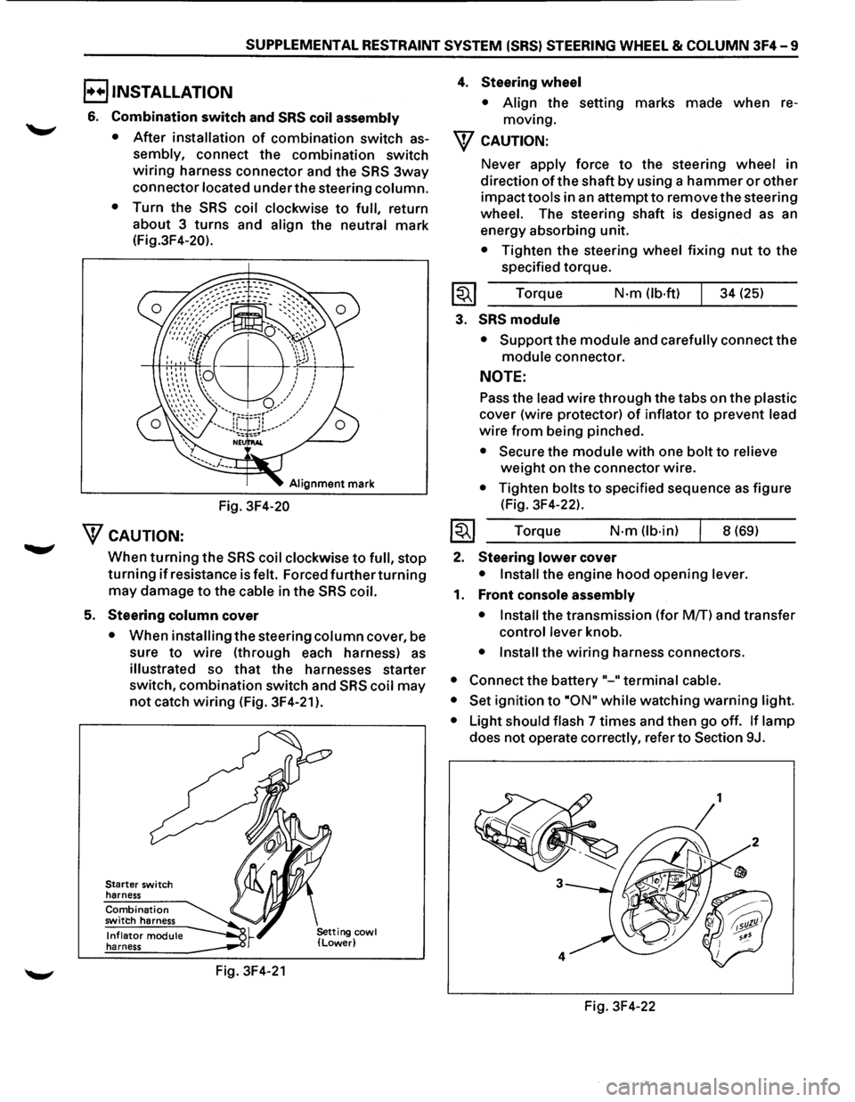
Turn the SRS coil clockwise to full, return
about 3
turns and align the neutral mark
(Fig.3F4-20).
Alignment mark
Fig. 3F4-20
WcAUTION:
When turning the SRS coil clockwise to full, stop
turning if resistance is felt. Forced further turning
may damage to the cable in the SRS coil.
5. Steering column cover
• When installing the steering column cover, be
sure
to wire (through each harness) as
illustrated so that the harnesses starter
switch,
combination switch and SRS coil may
not catch wiring (Fig. 3F4-21 ).
Starter switch
harness
Combination switch harness
Inflator module harness
Fig. 3F4-21
4. Steering wheel
• Align the setting marks made when re
moving.
W CAUTION:
Never apply force to the steering wheel in
direction
of the shaft by using a hammer or other
impact tools in an attempt to remove the steering
wheel. The steering shaft is designed as an
energy absorbing unit.
• Tighten the steering wheel fixing nut to the
specified torque.
Torque
N·m (lb-ft) 34 (25)
3. SRS module
• Support the module and carefully connect the
module connector.
NOTE:
Pass the lead wire through the tabs on the plastic
cover (wire protector) of inflator to prevent lead
wire from being pinched.
• Secure the module with one bolt to relieve
weight on the connector wire.
• Tighten bolts to specified sequence as figure
(Fig. 3F4-22).
Torque
N·m (lb·in) 8 (69)
2. Steering lower cover
• Install the engine hood opening lever.
1. Front console assembly
• Install
the transmission (for MfT) and transfer
control lever knob.
• Install the wiring harness connectors.
• Connect the battery "-"terminal cable.
• Set
ignition to ·oN" while watching warning light.
•
Light should flash 7 times and then go off. If lamp
does not operate correctly, refer to Section 9J.
Fig. 3F4-22
Page 220 of 1928
3F4-10 SUPPLEMENTAL RESTRAINT SYSTEM (SRS) STEERING WHEEL & COLUMN
LOCK CYLINDER REPLACEMENT
5
i
;;
9 ®
Fig. 3F4-23
E) REMOVAL
4
3
1
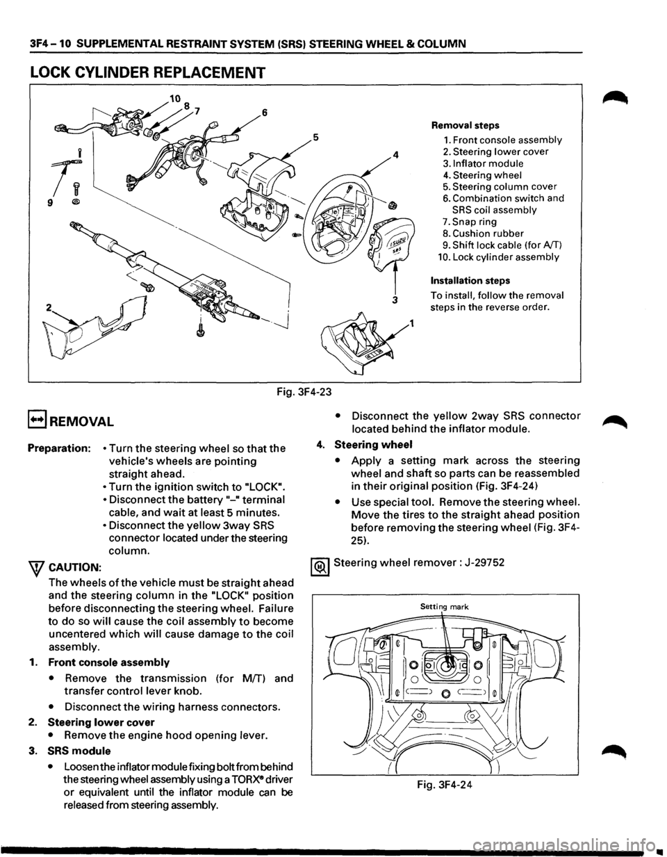
Removal steps
1. Front console assembly
2. Steering lower cover
3.1nflator module
4. Steering wheel
5. Steering column cover
6. Combination switch and
SRS coil assembly
7. Snap ring
8. Cushion rubber
9. Shift lock cable (for AfT)
10. Lock cylinder assembly
Installation steps
To install, follow the removal
steps in the reverse order.
• Disconnect the yellow 2way SRS connector
located behind the inflator module.
Preparation:
• Turn the steering wheel so that the
vehicle's wheels are
pointing
straight ahead.
4. Steering wheel
• Turn the ignition switch to "LOCK".
•
Disconnect the battery"-" terminal
cable, and wait at least 5 minutes.
• Disconnect the yellow 3way SRS
connector located under the steering
column.
• Apply a setting mark across the steering
wheel and
shaft so parts can be reassembled
in
their original position (Fig. 3F4-24)
• Use special tool. Remove the steering wheel.
Move the tires to the straight ahead position
before removing the steering wheel (Fig. 3F4-
25).
W CAUTION: 1®.1 Steering wheel remover: J-29752
The wheels
of the vehicle must be straight ahead
and the steering
column in the "LOCK" position
before disconnecting the steering wheel. Failure
Setting mark
to do so will cause the coil assembly to become
uncentered
which will cause damage to the coil
assembly.
1.
Front console assembly
• Remove the transmission (for Mff) and
transfer
control lever knob.
• Disconnect the wiring harness connectors.
2. Steering lower cover
• Remove the engine hood opening lever.
3. SRS module
• Loosen the inflator module fixing bolt from behind
the steering wheel assembly using a
TORXe driver
or equivalent until the inflator module can be
released from steering assembly. Fig.
3F4-24
•
Page 222 of 1928
3F4 -12 SUPPLEMENTAL RESTRAINT SYSTEM (SRS) STEERING WHEEL & COLUMN
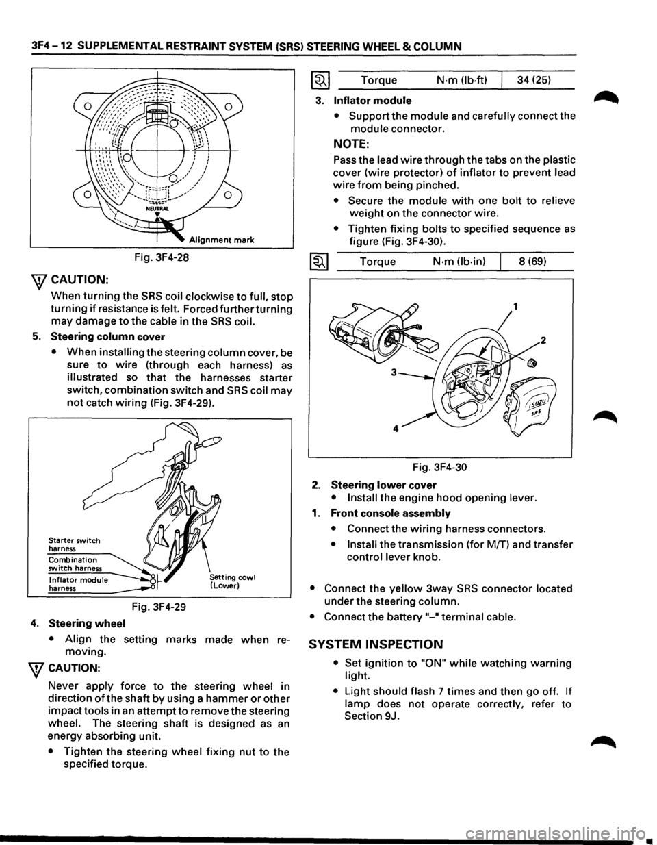
Alignment mark
Fig. 3F4-28
\fCAUTION:
When turning the SRS coil clockwise to full, stop
turning if resistance is felt. Forced further turning
may damage to the cable in the SRS coil.
5. Steering column cover
• When installing the steering column cover, be
sure
to wire (through each harness) as
illustrated so that the harnesses starter
switch,
combination switch and SRS coil may
not catch wiring (Fig. 3F4-29).
Starter switch
harness
Combination
switch harness
Inflator module
harness
4. Steering wheel
Fig. 3F4-29
• Align the setting marks made when re
moving.
\fCAUTION:
Never apply force to the steering wheel in
direction
of the shaft by using a hammer or other
impacttools in an attemptto remove the steering
wheel. The steering shaft is designed as an
energy absorbing unit.
• Tighten the steering wheel fixing nut to the
specified torque.
~~~ Torque N·m (lb-ft) 34 (25)
3. Inflator module
• Support the module and carefully connect the
module connector.
NOTE:
Pass the lead wire through the tabs on the plastic
cover (wire protector) of inflator to prevent lead
wire from being pinched.
• Secure the module with one bolt to relieve
weight on the connector wire.
• Tighten fixing bolts to specified sequence as
figure (Fig. 3F4-30).
1~1 Torque N·m (lb-in) 8 (69)
Fig.
3F4-30
2. Steering lower cover
• Install the engine hood opening lever.
1. Front console assembly
• Connect the wiring harness connectors.
• Install the transmission (for Mff) and transfer
control lever knob.
• Connect the yellow 3way SRS connector located
under the steering column.
• Connect the battery"-" terminal cable.
SYSTEM INSPECTION
• Set ignition to "ON" while watching warning
light.
•
Light should flash 7 times and then go off. If
lamp does not operate correctly, refer to
Section 9J.
Page 224 of 1928
3F4-14 SUPPLEMENTAL RESTRAINT SYSTEM (SRS) STEERING WHEEL & COLUMN
EJREMOVAL
Preparation: • Turn the steering wheel so that the
vehicle's
wheels are pointing straight
ahead.
• Turn the ignition switch to "LOCK".
•
Disconnect the battery "-" terminal
cable,
and wait at least 5 minutes.
• Disconnect the yellow 3way SRS
connector located under the steering
column.
wcAUTION:
The wheel of the vehicle must be straight ahead
and the steering
column in the "LOCK• position
before disconnecting the steering
column from
the steering gear.
Failure to do so will cause the SRS coil assembly
to become uncentered which will cause damage
to the SRS coil assembly.
1. Front console assembly
• Disconnect the transmission (for MfT) and
transfer
control lever knob.
• Disconnect the wiring harness connectors.
2. Steering lower cover
• Remove the engine hood opening lever.
3. Driver knee bolster (reinforcement)
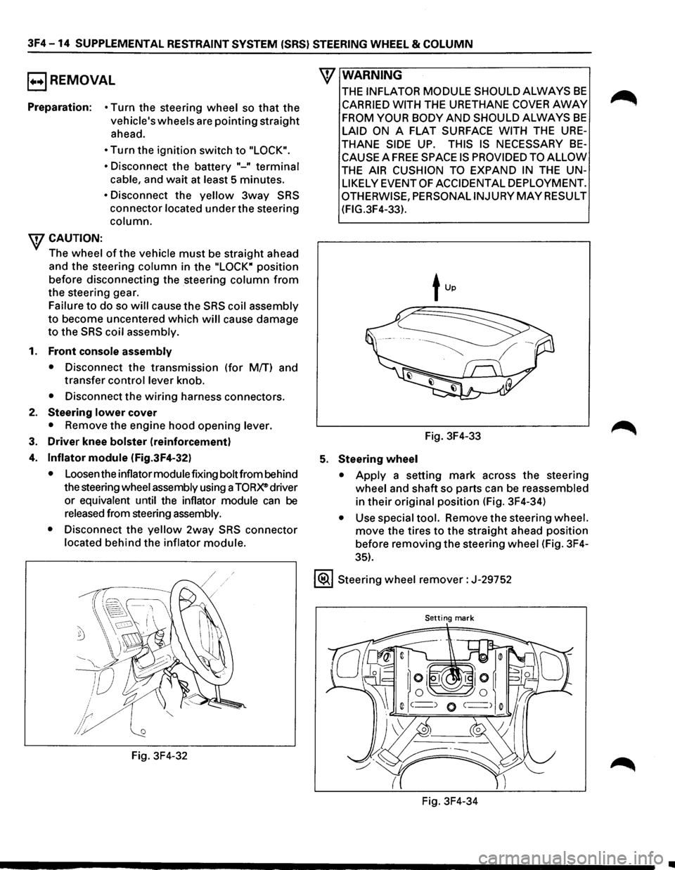
4. Inflator module (Fig.3F4-32)
• Loosen the inflator module fixing bolt from behind
the steering
wheel assembly using a TORX® driver
or
equivalent until the inflator module can be
released from steering assembly.
•
Disconnect the yellow 2way SRS connector
located behind the inflator module.
Fig. 3F4-32
\V WARNING
THE INFLATOR MODULE SHOULD ALWAYS BE
CARRIED WITH THE URETHANE COVER AWAY
FROM YOUR BODY AND SHOULD ALWAYS BE
LAID ON A FLAT SURFACE WITH THE URE
THANE SIDE UP. THIS IS NECESSARY BE
CAUSE A FREE SPACE IS PROVIDED TO ALLOW
THE AIR CUSHION TO EXPAND IN THE UN
LIKELY EVENT OF ACCIDENTAL DEPLOYMENT.
OTHERWISE, PERSONALINJURYMAYRESULT
(FIG.3F4-33).
Fig. 3F4-33
5. Steering wheel
• Apply a setting mark across the steering
wheel and shaft so parts can be reassembled
in their original position (Fig. 3F4-34)
• Use special tool. Remove the steering wheel.
move the tires to the straight ahead position
before removing the steering
wheel (Fig. 3F4-
35).
1®.1 Steering wheel remover: J-29752
Setting mark
Fig. 3F4-34
..
Page 226 of 1928
3F4-16 SUPPLEMENTAL RESTRAINT SYSTEM (SRS) STEERING WHEEL & COLUMN
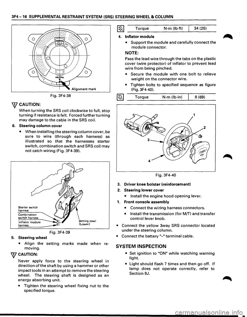
Alignment mark
Fig. 3F4-38
\fCAUTION:
When turning the SRS coil clockwise to full, stop
turning if resistance is felt. Forced furtherturning
may damage to the cable in the SRS coil.
6. Steering column cover
• When installing the steering column cover, be
sure
to wire (through each harness) as
illustrated so that the harnesses starter
switch,
combination switch and SRS coil may
not catch wiring (Fig. 3F4-39).
Starter switch
harness
Combination switch harness
Inflator module harness
5. Steering wheel
Fig. 3F4-39
• Align the setting marks made when re
moving.
WCAUTION:
Never apply force to the steering wheel in
direction
ofthe shaft by using a hammer or other
impacttools in an attempt to remove the steering
wheel. The steering
shaft is designed as an
energy absorbing unit.
• Tighten the steering wheel fixing nut to the
specified torque. Torque
N·m (lb·ftl 34
(25)
4. Inflator module
• Support the module and carefully connect the
module connector.
NOTE:
Pass the lead wire through the tabs on the plastic
cover (wire protector) of inflator to prevent lead
wire from being pinched.
• Secure the module with one bolt to relieve
weight on the connector wire.
• Tighten bolts to specified sequence as figure
(Fig. 3F4-40).
Torque
N·m (lb-in) 8 (69)
Fig. 3F4-40
3. Driver knee bolster (reinforcement)
2. Steering lower cover
• Install the engine hood opening lever.
1. Front console assembly
• Connect the wiring harness connectors.
• Install the transmission (for M/T) and transfer
control lever knob.
• Connect the yellow 3way SRS connector located
under the steering column.
• Connect the battery "-"terminal cable.
SYSTEM INSPECTION
• Set ignition to "ON" while watching warning
light.
• Light should flash 7 times and then go off. If
lamp does not operate correctly, refer to
Section 9J.
•
Page 240 of 1928
4A-12 PROPELLER SHAFT
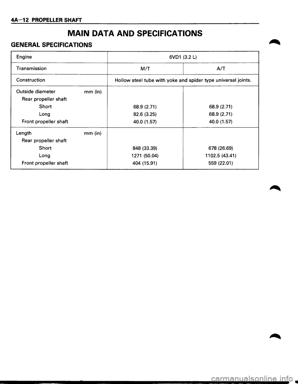
MAIN DATA AND SPECIFICATIONS
GENERAL SPECIFICATIONS
Engine 6VD1 (3.2 L)
Transmission MIT A/T
Construction Hollow steel tube with yoke and spider type universal joints.
Outside diameter mm (in)
Rear
propeller shaft
Short 68.9 (2.71) 68.9
(2.71)
Long 82.6 (3.25) 68.9
(2.71)
Front
propeller shaft 40.0 (1.57) 40.0 (1.57)
Length
mm (in)
Rear
propeller shaft
Short 848 (33.39) 678
(26.69)
Long
1271 (50.04) 11 02.5 (43.41)
Front
propeller shaft 404 (15.91) 559 (22.01)
..