battery ISUZU TROOPER 1995 Workshop Manual
[x] Cancel search | Manufacturer: ISUZU, Model Year: 1995, Model line: TROOPER, Model: ISUZU TROOPER 1995Pages: 1928
Page 1536 of 1928
8-346 CHASSIS ELECTRICAL
SUN ROOF
GENERAL DESCRIPTION
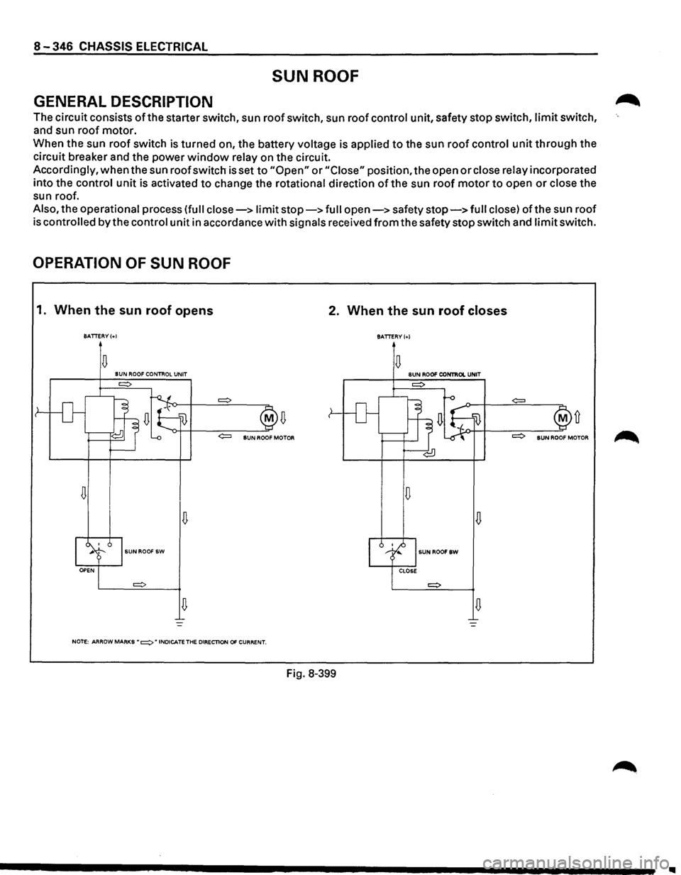
The circuit consists of the starter switch, sun roof switch, sun roof control unit, safety stop switch, limit switch,
and sun roof motor.
When the sun
roof switch is turned on, the battery voltage is applied to the sun roof control unit through the
circuit breaker and the power
window relay on the circuit.
Accordingly,
when the sun roof switch is set to "Open" or "Close" position, the open or close relay incorporated
into the control
unit is activated to change the rotational direction of the sun roof motor to open or close the
sun roof.
Also, the operational process (full close-> limit stop-> full open-> safety stop-> full close) ofthe sun roof
is
controlled by the control unit in accordance with signals received from the safety stop switch and limit switch.
OPERATION OF SUN ROOF
1. When the sun roof opens 2. When the sun roof closes
BATTERY(+!
BATTERY(+)
D D SUN ROOF CONTROL UNIT SUN ROO!' CONTIIOI. UNIT
D D
D
D
SUNROOF SW SUNROOFSW
D D
NOTE: ARROW MARKS • =:> • INDICATE THE DIRECTlON 01' CURRENT.
Fig. 8-399
Ill
Page 1537 of 1928
"'TI ce· (X) I "" 0 0
(
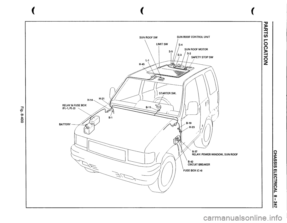
RELAY
& FUSE
BOX
IFL-1,
FL-2)
H-14
BATTERY
' -
,¢_
( SUN
ROOFSW
LIMITSW
SUN
ROOF
CONTROL
UNIT
SAFETY
STOP
SW
I " B-37 RELAY:
POWER
WINDOW,
SUN
ROOF
B-42 CIRCUIT
BREAKER
(
~ ::a -1 en r-0 (") ~ 0 2
0 :I: )> CJ) CJ) c;; m rm ~ ::D ~ r-eo I w .,. -..I
Page 1541 of 1928
CHASSIS ELECTRICAL 8-351
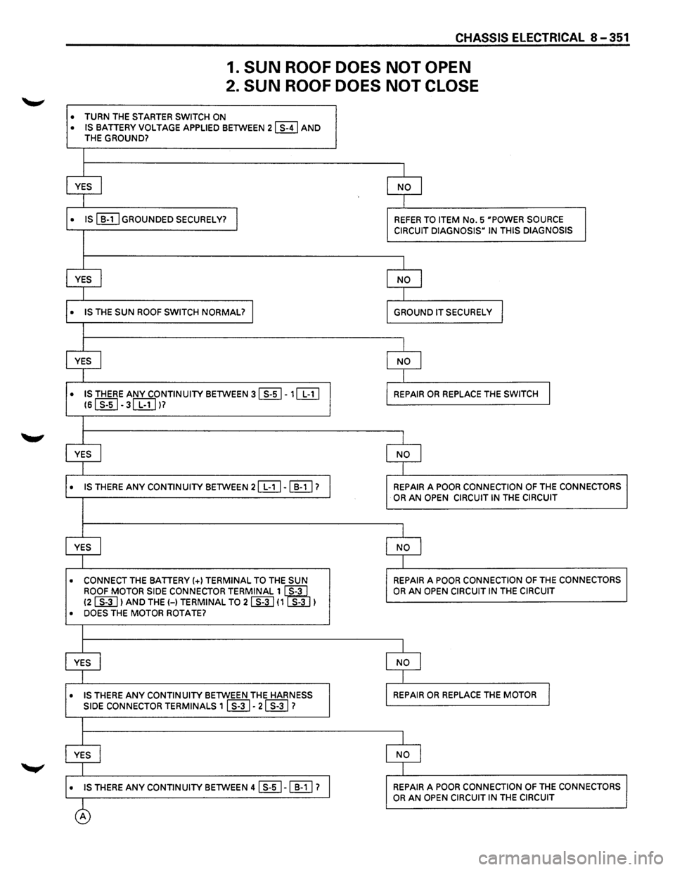
1. SUN ROOF DOES NOT OPEN
2. SUN ROOF DOES NOT CLOSE
• TURN THE STARTER SWITCH ON
• IS BATTERY VOLTAGE APPLIED BETWEEN 21 S-41 AND THE GROUND?
I
YES I NO J
I
• IS ~GROUNDED SECURELY? I REFER TO ITEM No.5 uPOWER SOURCE
CIRCUIT DIAGNOSISu IN THIS DIAGNOSIS
I
YES I NO I
I
• IS THE SUN ROOF SWITCH NORMAL? I GROUND IT SECURELY I
I
YES j NO I
I
• IS THERE ANY CONTINUITY BETWEEN 3 ~-1 ~ REPAIR OR REPLACE THE SWITCH I lSI s-si-3[BJl?
I
YES I NO I
I
• IS THERE ANY CONTINUITY BETWEEN 2 [BJ-~? REPAIR A POOR CONNECTION OF THE CONNECTORS OR AN OPEN CIRCUIT IN THE CIRCUIT
I
YES I NO I
I
• CONNECT THE BATTERY(+) TERMINAL TO THE SUN REPAIR A POOR CONNECTION OF THE CONNECTORS
ROOF MOTOR SIDE CONNECTOR TERMINAL
1 ~ OR AN OPEN CIRCUIT IN THE CIRCUIT
(2 ~I AND THE(-) TERMINAL TO 2 ~ (1 S-3 I
• DOES THE MOTOR ROTATE?
I
YES I NO I
I
• IS THERE ANY CONTINUITY BETWEEN THE HARNESS REPAIR OR REPLACE THE MOTOR I SIDE CONNECTOR TERMINALS 1 ~-21 S-31 ?
I
YES I NO I
I
• IS THERE ANY CONTINUITY BETWEEN 4 ~-~ ? REPAIR A POOR CONNECTION OF THE CONNECTORS
0
OR AN OPEN CIRCUIT IN THE CIRCUIT
Page 1546 of 1928
8-356 CHASSIS ELECTRICAL
SUN ROOF SWITCH
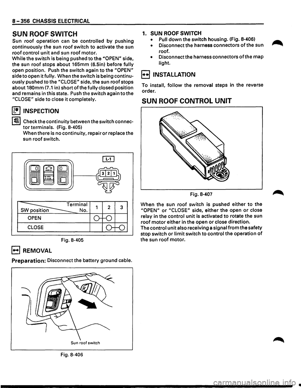
Sun roof operation can be controlled by pushing
continuously the sun
roof switch to activate the sun
roof control
unit and sun roof motor.
While the switch is being pushed
to the "OPEN" side,
the sun roof stops about 165mm (6.5in) before
fully
open position. Push the switch again to the "OPEN"
side to open it fully. When the switch is being continu
ously pushed to the
"CLOSE" side, the sun roof stops
about
180mm (7 .1 in) short ofthe fully closed position
and remains
in this state. Push the switch again to the
"CLOSE" side to close it completely.
~ INSPECTION
I tjt I Check the continuity between the switch connec
tor terminals. (Fig. 8-405)
When there is no continuity, repair or replace the
sun roof switch.
3
CLOSE
Fig. 8-405
E) REMOVAL
Preparation: Disconnect the battery ground cable.
Sun roof switch
Fig. 8-406
1. SUN ROOF SWITCH
• Pull down the switch housing. (Fig. 8-406)
•
Disconnect the harness connectors of the sun
roof.
• Disconnectthe harness connectors ofthe map
light.
E_3 INSTALLATION
To install, follow the removal steps in the reverse
order.
SUN ROOF CONTROL UNIT
Fig. 8-407
When the sun roof switch is pushed either to the
"OPEN" or "CLOSE" side, either the open or close
relay in the control
unit is activated to rotate the sun
roof motor either in the open or close direction.
The control unit also receiving a signal
from the safety
stop switch
or limit switch to control the operation of
the sun roof motor.
Page 1547 of 1928
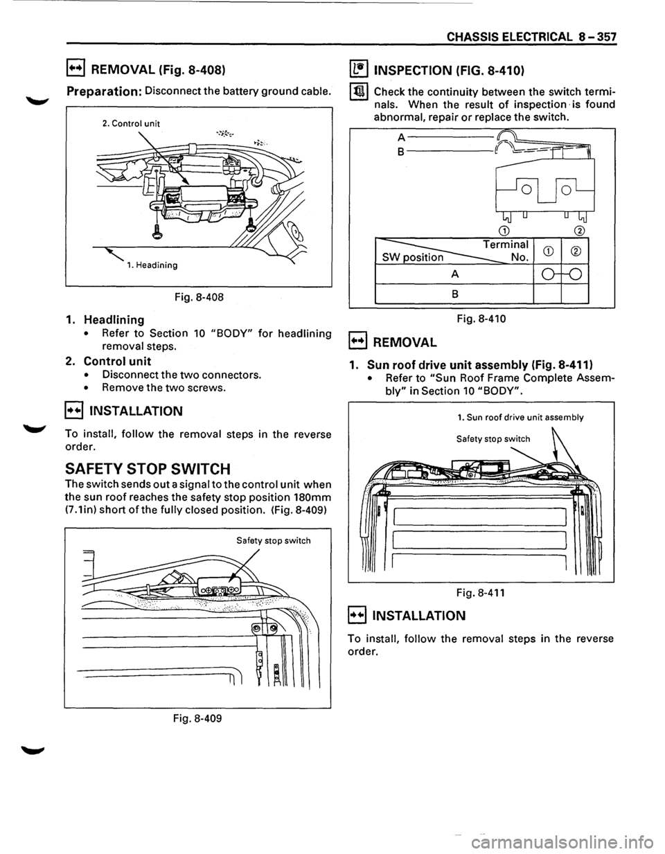
l+o+l REMOVAL (Fig. 8-408)
Preparation: Disconnect the battery ground cable.
2. Control unit
1. Headining
Fig. 8-408
1. Headlining
• Refer to Section 10 "BODY" for headlining
removal
steps.
2. Control unit
• Disconnect the two connectors.
• Remove the two screws.
EJ INSTALLATION
To install, follow the removal steps in the reverse
order.
SAFETY STOP SWITCH
The switch sends out a signal to the control unit when
the sun
roof reaches the safety stop position 180mm
(7 .1 in) short of the fully closed position. (Fig. 8-409)
Safety stop switch
Fig. 8-409
CHASSIS ELECTRICAL 8-357
~ INSPECTION (FIG. 8-410)
I tj I Check the continuity between the switch termi
nals. When the result of inspection· is found
abnormal, repair or replace the switch.
A-----
B------
B
Fig. 8-410
B REMOVAL
1. Sun roof drive unit assembly (fig. 8-411)
• Refer to "Sun Roof Frame Complete Assem
bly" in Section 10 "BODY".
1. Sun roof drive unit assembly
Fig. 8-411
B INSTALLATION
To install, follow the removal steps in the reverse
order.
Page 1549 of 1928
![ISUZU TROOPER 1995 Workshop Manual SUN ROOF MOTOR
~ INSPECTION
[]1]
I
~rminal
S p No.
Sun roof open side
Sun roof close side
Fig. 8-415 1
2
~ 8
8
~
Apply the battery voltage to the connector terminals
ofthe sun roof mo](/img/61/57183/w960_57183-1548.png "ISUZU TROOPER 1995 Workshop Manual SUN ROOF MOTOR
~ INSPECTION
[]1]
I
~rminal
S p No.
Sun roof open side
Sun roof close side
Fig. 8-415 1
2
~ 8
8
~
Apply the battery voltage to the connector terminals
ofthe sun roof mo")
SUN ROOF MOTOR
~ INSPECTION
[]1]
I
~rminal
S p No.
Sun roof open side
Sun roof close side
Fig. 8-415 1
2
~ 8
8
~
Apply the battery voltage to the connector terminals
ofthe sun roof motor to check its function (Fig. 8-415).
B REMOVAL (FIG. 8-416)
Preparation: Disconnect the battery ground cable.
2. Sun roof motor
1. Headlining
I
Fig.S-416
1. Headlining
• Refer to "Headlining" in Section 10 "Body".
2. Sun roof motor
• Disconnect the connector.
• Remove the three nuts and two screws.
E3 INSTALLATION
To install, follow the removal steps in the reverse
order.
CHASSIS ELECTRICAL 8-359
POWER WINDOW RELAY
(b!] INSPECTION
r·-----,
_..i___/ o----1..4> Q) I I
Fig. 8-417
lt!lll Check to see if there is continuity between the
relay terminals. (Fig. 8-417)
Replace
the relay when the result of inspection is
found abnormal.
®-@ ....... No Continuity
(When the battery voltage is applied between
CD-@)
®-@ ....... Continuity
NOTE:
For the relay removal, refer to "Connector Handling"
in the "NOTES FOR WORKING ON ELECTRICAL
ITEMS"
in this section.
Page 1555 of 1928
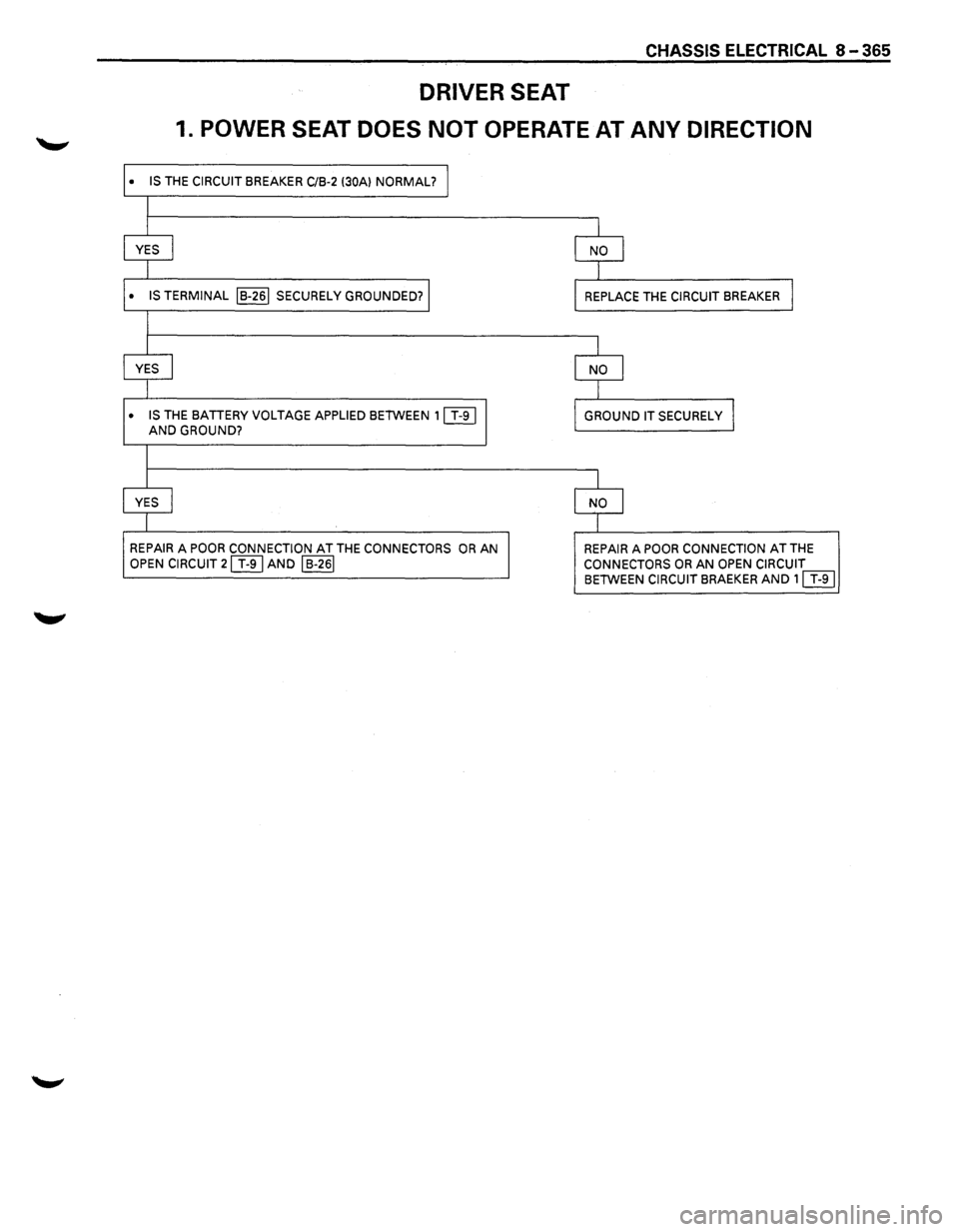
CHASSIS ELECTRICAL 8-365
DRIVER SEAT
1. POWER SEAT DOES NOT OPERATE AT ANY DIRECTION
• IS THE CIRCUIT BREAKER C/B-2 (30A} NORMAL? l
I
I
I
YES I NO J
I l
• IS TERMINAL IB-261 SECURELY GROUNDED? I REPLACE THE CIRCUIT BREAKER J
I
I I
YES I NO I
I I
• IS THE BATTERY VOLTAGE APPLIED BETWEEN 11 T-91
GROUND IT SECURELY I AND GROUND?
I
I I
YES I NO j
I
I
REPAIR A POOR CONNECTION AT THE CONNECTORS OR AN REPAIR A POOR CONNECTION AT THE
OPEN CIRCUIT 21 T-9 I AND I B-261 CONNECTORS OR AN OPEN CIRCUIT BETWEEN CIRCUIT BRAEKER AND 11 T-9 I
Page 1565 of 1928
, cE" 00 I ~ ~
SEAT
HEATER·BACK
IRHI,
',
SEAT
HEATER
SW
IRHI
"·
SEAT
HEATER-CUSHION
(RHI
RELAY
& FUSE
BOX
IFL-1,
FL-21
H-14
BATTERY
/ '
#..
(
(
SEAT
HEATER-BACK
ILHI
SEAT
HEATER-CUSHION
(lH)
SEAT
HEATER
SW
ILHI
FRONT
CONSOLE
ASSEMBLY
~ ~ r-0 0 ~ -0 2
n ::t 1: (/) c;; m rm ~ ::D 0 )> r-01) I w ..... C1l
Page 1569 of 1928
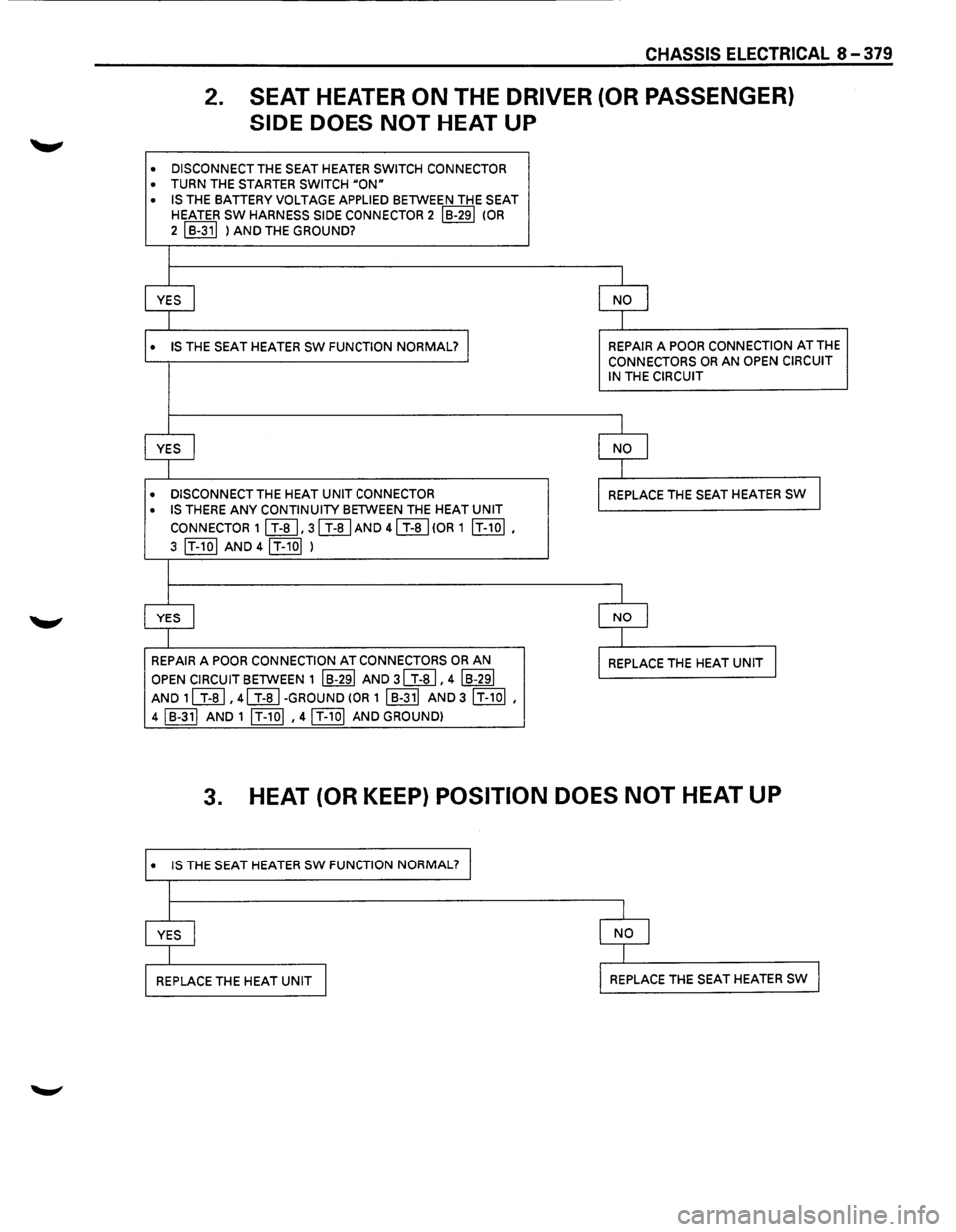
CHASSIS ELECTRICAL 8-379
2. SEAT HEATER ON THE DRIVER (OR PASSENGER)
SIDE DOES NOT HEAT UP
• DISCONNECT THE SEAT HEATER SWITCH CONNECTOR
• TURN THE STARTER SWITCH uoN"
• IS THE BATTERY VOLTAGE APPLIED BETWEEN THE SEAT HEATER SW HARNESS SIDE CONNECTOR 2 IB-291 (OR
2 I B-311 ) AND THE GROUND?
I
YES
I NO I
1
• IS THE SEAT HEATER sw FUNCTION NORMAL? I REPAIR A POOR CONNECTION AT THE CONNECTORS OR AN OPEN CIRCUIT
IN
THE CIRCUIT
I
YES
I NO l
I
• DISCONNECT THE HEAT UNIT CONNECTOR REPLACE THE SEAT HEATER SW I
• IS THERE ANY CONTINUITY BETWEEN THE HEAT UNIT
CONNECTOR 11 T-a I. 31 T-al AND 41 T-ai(OR 1 IT-101.
3 IT-101 AND 4IT-10I )
l
YES I NO l
I
REPAIR
A POOR CONNECTION AT CONNECTORS OR AN REPLACE THE HEAT UNIT l
OPEN CIRCUIT BETWEEN 1 IB-291 AND 31 T-al. 4 IB-291
AND 1l T-al. 41 T-al-GROUND (OR 1 I B-311 AND 3 IT-1ol •
4 I B-311 AND 1 IT-101 • 41 T-101 AND GROUND)
3. HEAT (OR KEEP) POSITION DOES NOT HEAT UP
• IS THE SEAT HEATER SW FUNCTION NORMAL?
Page 1570 of 1928
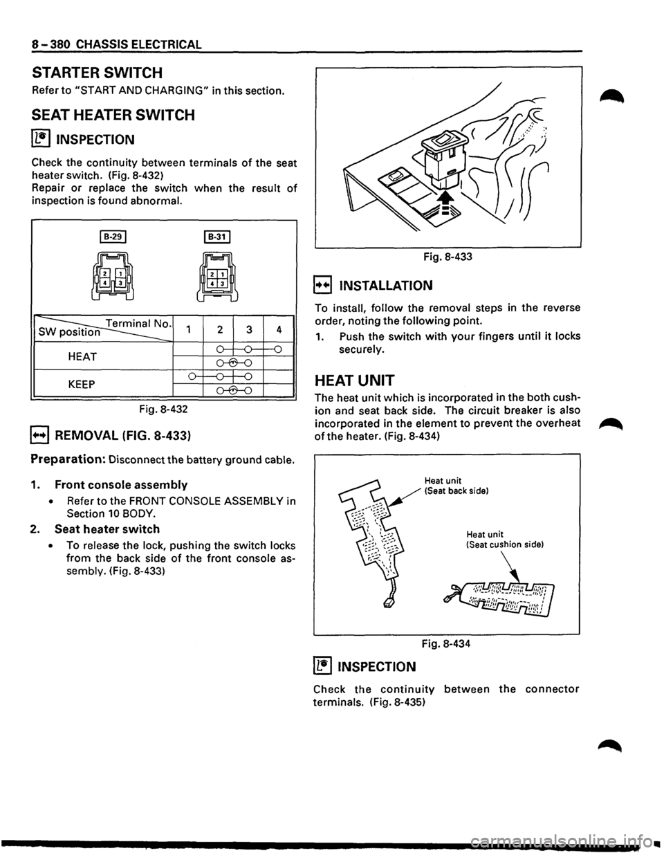
8-380 CHASSIS ELECTRICAL
STARTER SWITCH
Refer to "START AND CHARGING" in this section.
SEAT HEATER SWITCH
~ INSPECTION
Check the continuity between terminals of the seat
heater switch. (Fig. 8-432)
Repair
or replace the switch when the result of
inspection is found abnormal.
I B-291 I B-31 I
ji
8
s ~0. 1 2 3 4
HEAT o--:---0= f--0
o-6--0
o---0---j-0 KEEP o-6--0
Fig. 8-432
B REMOVAL (FIG. 8-433)
Preparation: Disconnect the battery ground cable.
1. Front console assembly
• Refer to the FRONT CONSOLE ASSEMBLY in
Section 10 BODY.
2. Seat heater switch
• To release the lock, pushing the switch locks
from the back side of the front console as
sembly. (Fig. 8-433) Fig.
8-433
B INSTALLATION
To install, follow the removal steps in the reverse
order, noting the
following point.
1. Push the switch with your fingers until it locks
securely.
HEAT UNIT
The heat unit which is incorporated in the both cush
ion and seat back side. The circuit breaker is also
incorporated in the element to prevent the overheat ~
of the heater. (Fig. 8-434)
Heat unit
(Seat back side)
Heat
unit (Seat cushion side)
Fig. 8-434
~ INSPECTION
Check the continuity between the connector
terminals. (Fig. 8-435)
..