battery ISUZU TROOPER 1995 Workshop Manual
[x] Cancel search | Manufacturer: ISUZU, Model Year: 1995, Model line: TROOPER, Model: ISUZU TROOPER 1995Pages: 1928
Page 1596 of 1928
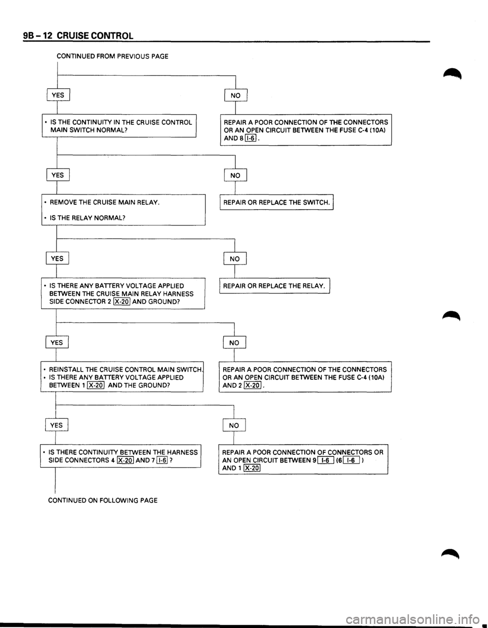
98-12 CRUISE CONTROL
CONTINUED FROM PREVIOUS PAGE
~ $
• IS THE CONTINUITY IN THE CRUISE CONTROL .I REPAIR A POOR CONNECTION OF THE CONNECTORS MAIN SWITCH NORMAL? OR AN OPEN CIRCUIT BETWEEN THE FUSE C-4 (10Al
AND B[E[].
~ $
• REMOVE THE CRUISE MAIN RELAY. REPAIR OR REPLACE THE SWITCH.j
• IS THE RELAY NORMAL?
~ $
• IS THERE ANY BATTERY VOLTAGE APPLIED
REPAIR OR REPLACE THE RELAY. I BETWEEN THE CRUISE MAIN RELAY HARNESS
SIDE CONNECTOR 2IX-20I AND GROUND?
~ $
• REINSTALL THE CRUISE CONTROL MAIN SWITCH. REPAIR A POOR CONNECTION OF THE CONNECTORS
• IS THERE ANY BATTERY VOLTAGE APPLIED OR AN OPEN CIRCUIT BETWEEN THE FUSE C-4 (10AI
BETWEEN 1IX-20I AND THE GROUND? AND 2IX-20 I.
~ $
• IS THERE CONTINUITY BETWEEN THE HARNESS
REPAIR A POOR CONNECTION OF CONNECTORS OR SIDE CONNECTORS 4IX-20 I AND 7 [§)? AN OPEN CIRCUIT BETWEEN 9[ill 16[W I AND 1IX-20I
CONTINUED ON FOLLOWING PAGE
..
Page 1604 of 1928
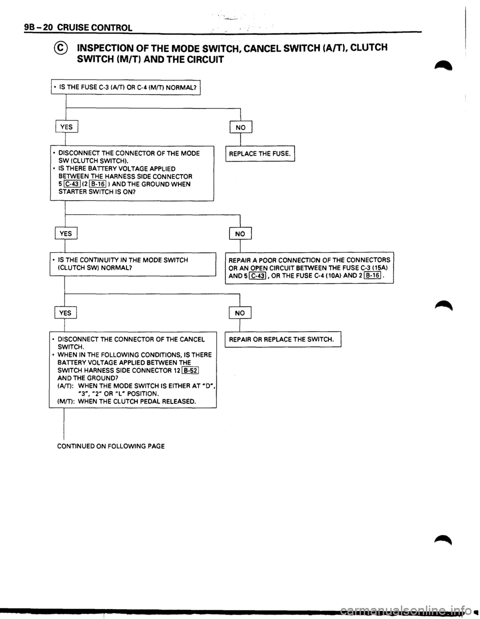
98-20 CRUISE CONTROL
@ INSPECTION OF THE MODE SWITCH, CANCEL SWITCH (A/T), CLUTCH
SWITCH
(M/T) AND THE CIRCUIT
• IS THE FUSE C-3 IA/TI OR C-4 IMfTI NORMAL?
• DISCONNECT THE CONNECTOR OF THE MODE SW (CLUTCH SWITCH).
• IS THERE BATTERY VOLTAGE APPLIED
BETWEEN THE HARNESS SIDE CONNECTOR SIC-431 121 B-1611 AND THE GROUND WHEN STARTER SWITCH IS ON?
• IS THE CONTINUITY IN THE MODE SWITCH !CLUTCH SW) NORMAL?
•
DISCONNECT THE CONNECTOR OF THE CANCEL SWITCH.
• WHEN IN THE FOLLOWING CONDITIONS, IS THERE BATTERY VOLTAGE APPLIED BETWEEN THE
SWITCH HARNESS SIDE CONNECTOR 121 B-521 AND THE GROUND?
(A/T): WHEN THE MODE SWITCH IS EITHER AT "D",
"3", "2" OR "L" POSITION. (MfTI: WHEN THE CLUTCH PEDAL RELEASED.
CONTINUED ON FOLLOWING PAGE
REPAIR A POOR CONNECTION OF THE CONNECTORS
OR AN OPEN CIRCUIT BETWEEN THE FUSE C-3 I 15A) AND 51 C-431, OR THE FUSE C-4 (10AI AND 21 B-161.
..
Page 1613 of 1928
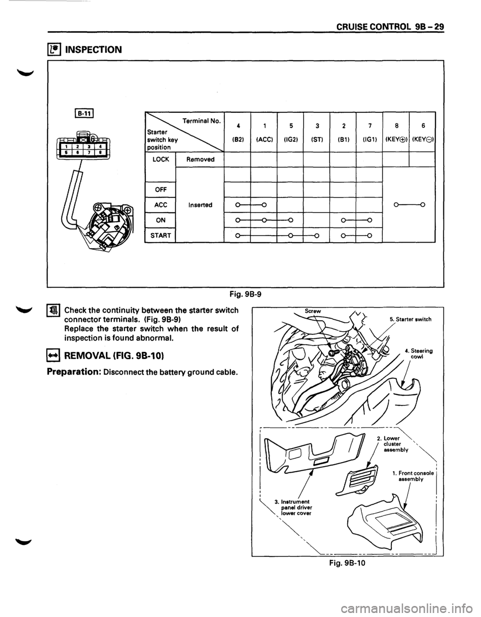
~ INSPECTION
I B-111
~
4 1
(82)
IACCI
LOCK Removed
OFF
ACC Inserted
ON -
START
Fig. 98-9
I t!l Check the continuity between the starter switch
connector
terminals. (fig. 98-9)
Replace the starter switch when the result of
inspection is found abnormal.
B REMOVAL (FIG. 98-10)
Preparation: Disconnect the battery ground cable.
5 3
IIG2) 1ST)
CRUISE CONTROL 98-29
2 7
(81) IIG1)
Fig. 98-10
8 6
IKEY(j;)) IKEY81
o----o
5. Starter switch
I
I
1. Front console I assembly
Page 1615 of 1928
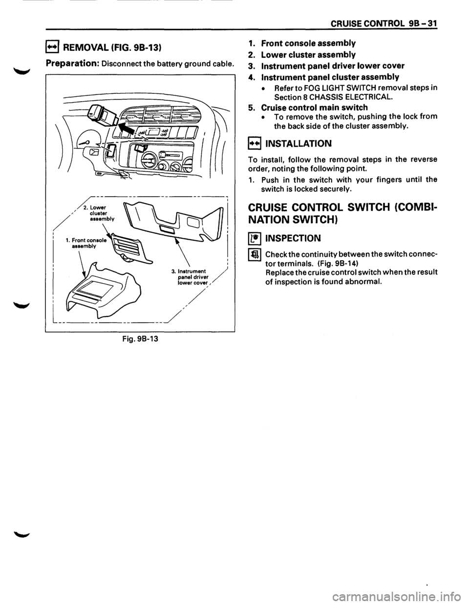
B REMOVAL (FIG. 98-13)
Preparation: Disconnect the battery ground cable.
Fig.
98-13
CRUISE CONTROL 98-31
1. Front console assembly
2. Lower cluster assembly
3. Instrument panel driver lower cover
4. Instrument panel cluster assembly
• Refer to FOG LIGHT SWITCH removal steps in
Section 8 CHASSIS ELECTRICAL.
5. Cruise control main switch
• To remove the switch, pushing the lock from
the back side of the cluster assembly.
B INSTALLATION
To install, follow the removal steps in the reverse
order, noting the
following point.
1. Push in the switch with your fingers until the
switch is locked securely.
CRUISE CONTROL SWITCH (COMBI
NATION SWITCH)
(b!] INSPECTION
I till Check the continuity between the switch connec
tor terminals. (Fig. 98-14)
Replace the cruise control switch when the result
of inspection is found abnormal.
Page 1618 of 1928
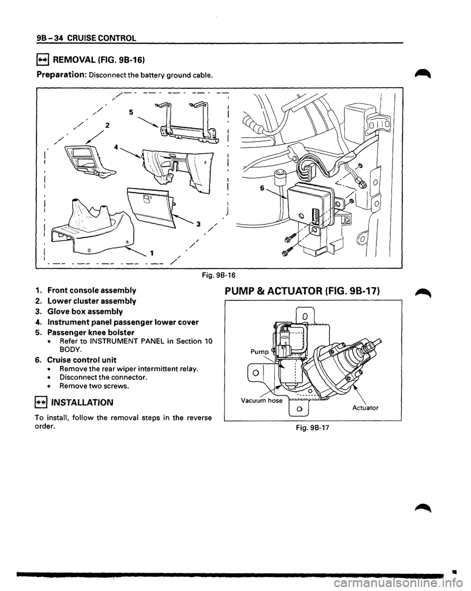
98-34 CRUISE CONTROL
B REMOVAL (FIG. 98-16)
Preparation: Disconnect the battery ground cable.
/-----/
I
J
Fig. 98-16
1. Front console assembly
2. Lower cluster assembly
3. Glove box assembly
4. Instrument panel passenger lower cover
5. Passenger knee bolster
• Refer to INSTRUMENT PANEL in Section 10
BODY.
6. Cruise control unit
• Remove the rear wiper intermittent relay.
• Disconnect the connector.
• Remove two screws.
E) INSTALLATION
To install, follow the removal steps in the reverse
order.
PUMP & ACTUATOR (FIG. 98-17)
Actuator
Fig. 98-17
..
Page 1619 of 1928
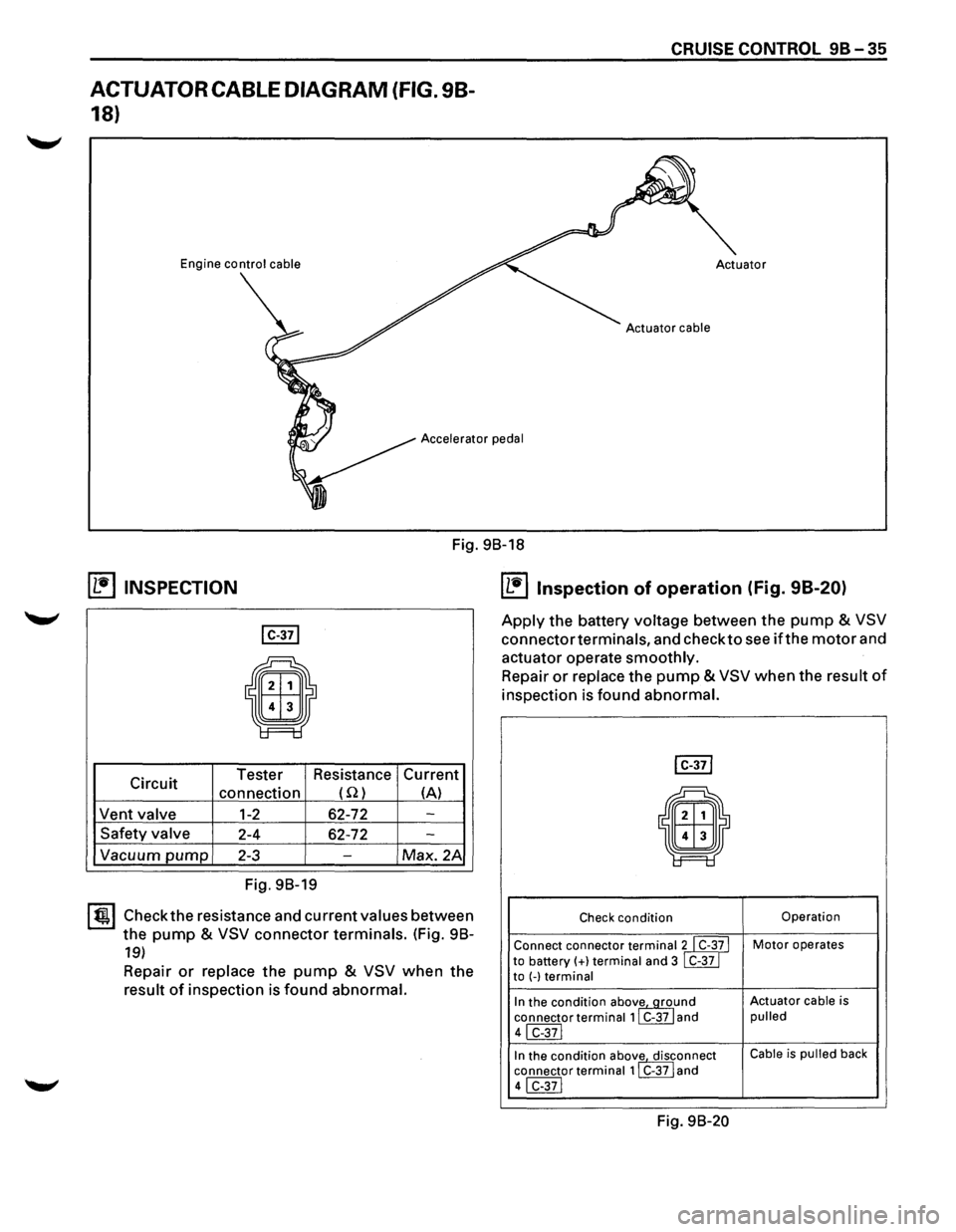
ACTUATOR CABLE DIAGRAM (FIG. 98-
18)
Engine control cable
CRUISE CONTROL 9B-35
Accelerator pedal
Fig. 98-18
~ INSPECTION
I C-371
E9
Circuit Tester
Resistance Current
connection (Q) (A)
Vent
valve 1-2 62-72 -
Safety valve 2-4 62-72 -
Vacuum pump 2-3 -Max. 2A
Fig. 98-19
I~~ Check the resistance and current values between
the
pump & VSV connector terminals. (Fig. 98-
19)
Repair or replace the pump & VSV when the
result of inspection is found abnormal.
IL1i'llnspection of operation (Fig. 98-20)
Apply the battery voltage between the pump & VSV
connector terminals, and check to see if the motor and
actuator operate
smoothly.
Repair or replace the pump & VSV when the result of
inspection is found abnormal.
I C-371
il
Check condition Operation
Connect connector
terminalll C-3~ I Motor operates
to battery(+} terminal and 3 C-37 to (-)terminal
In the condition abov~und Actuator cable is
connector
terminal 1 C-37 and pulled
41 C-371
In the condition abov
1e. disrnnect Cable is pulled back
connector
terminal 1 C-37 and
41 C-371
Fig. 98-20
Page 1620 of 1928
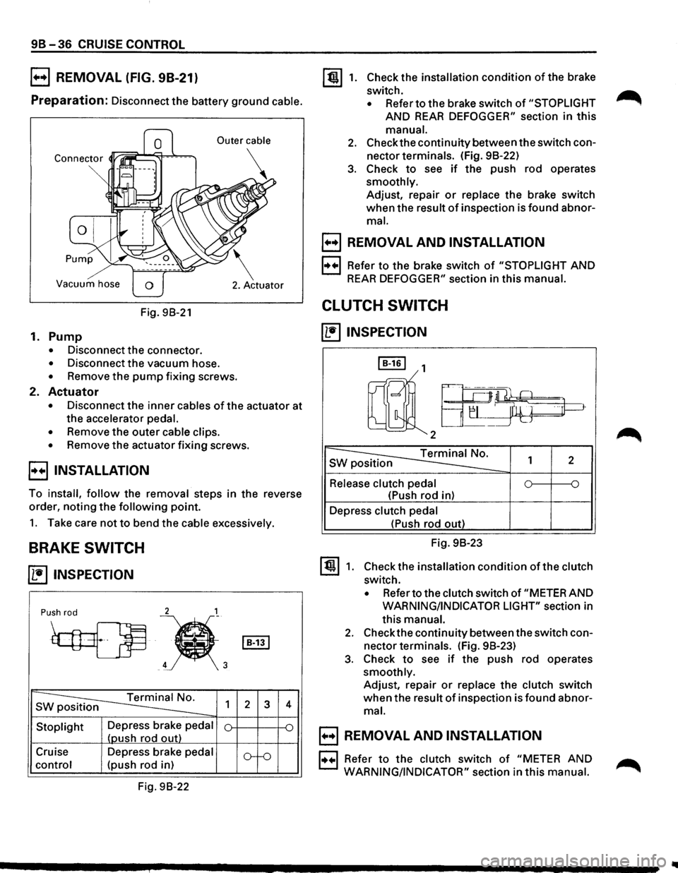
9B-36 CRUISE CONTROL
B REMOVAL (FIG. 98-21)
Preparation: Disconnect the battery ground cable.
Vacuum hose
Fig. 98-21
1. Pump
• Disconnect the connector.
• Disconnect the vacuum hose.
• Remove the pump fixing screws.
2. Actuator
• Disconnect the inner cables of the actuator at
the accelerator
pedal.
•
Remove the outer cable clips.
• Remove the actuator fixing screws.
E) INSTALLATION
To install, follow the removal steps in the reverse
order, noting
the following point.
1. Take care not to bend the cable excessively.
BRAKE SWITCH
~ INSPECTION
2 1
Push rod
~
~'
s ~ 1
Stoplight Depress brake pedal
(oush rod out)
Cruise Depress brake
pedal
control (push rod in)
Fig. 98-22
I B-131
2 3
o--o
4
~1. Check the installation condition of the brake
switch.
• Refer to the brake switch of "STOPLIGHT
AND REAR DEFOGGER" section in this
manual.
2. Check the continuity between the switch con
nector terminals. (Fig. 98-22)
3. Check to see if the push rod operates
smoothly. Adjust, repair
or replace the brake switch
when the result
of inspection is found abnor
mal.
B REMOVAL AND INSTALLATION
1·++·1 Refer to the brake switch of "STOPLIGHT AND
REAR DEFOGGER" section in this manual.
CLUTCH SWITCH
~INSPECTION
I B-161 1
rnll2a-~~
~ s 1 2
Release clutch pedal 0 ~ ~
(Push rod in)
Depress
clutch pedal
~1.
(Push rod out)
Fig. 98-23
Check the installation
condition of the clutch
switch.
• Refer to the clutch switch of "METER AND
WARNING/INDICATOR LIGHT" section in
this
manual.
2. Check the continuity between the switch con
nector terminals. (Fig. 98-23)
3. Check to see if the push rod operates
smoothly. Adjust, repair
or replace the clutch switch
when the result of inspection is found abnor
mal.
B REMOVAL AND INSTALLATION
1••1 Refer to the clutch switch of "METER AND ...-...
WARNING/INDICATOR"
section in this manual. ,...........
Page 1623 of 1928
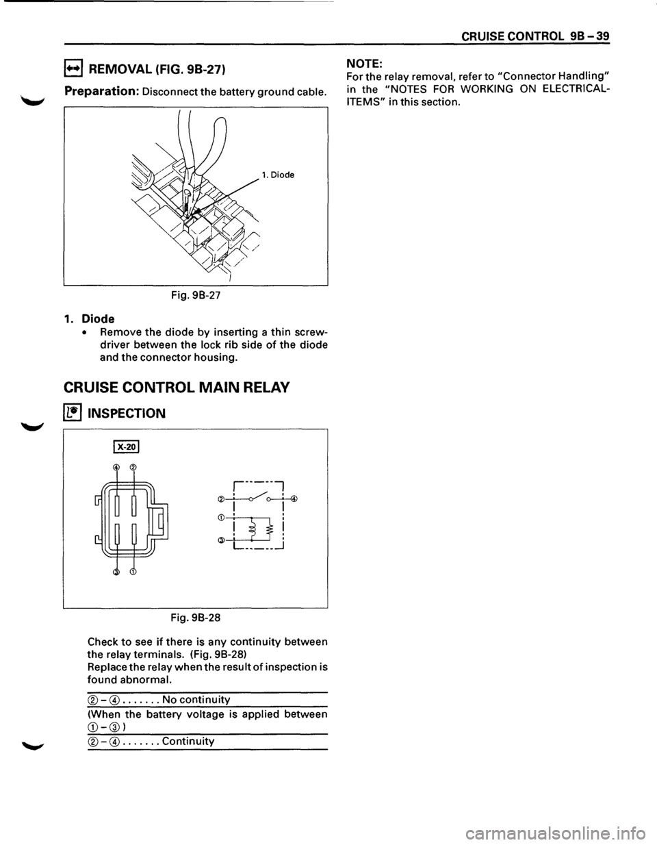
B REMOVAL (FIG. 98-27)
Preparation: Disconnect the battery ground cable.
1. Diode
Fig. 98-27
1. Diode
• Remove the diode by inserting a thin screw
driver between the lock rib side of the diode
and the connector housing.
CRUISE CONTROL MAIN RELAY
~ INSPECTION
@ ®
,-----,
®~~ I I
Q)~!
~J___l___J . L _____ _j
Fig. 98-28
Check
to see if there is any continuity between
the
relay terminals. (Fig. 98-28)
Replace the relay when the result of inspection is
found abnormal.
®-@ ....... No continuity
(When the battery voltage is applied between
CD-®l
®-@ ....... Continuity
CRUISE CONTROL 98-39
NOTE:
For the relay removal, refer to "Connector Handling"
in the "NOTES FOR WORKING ON ELECTRICAL
ITEMS"
in this section.
Page 1629 of 1928
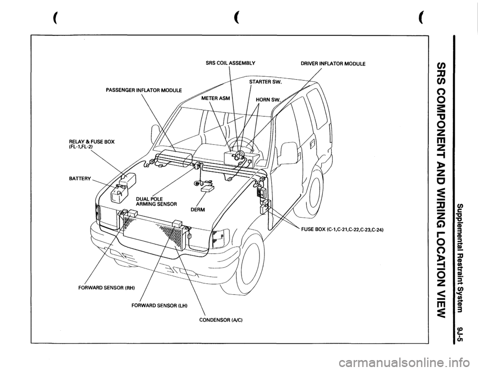
(
PASSENGER
INFLATOR
MODULE
RELAY
& FUSE
BOX
(FL-l,FL-2) BATTERY
FORWARD
SENSOR
IRH)
(
(
SRS
COIL
ASSEMBLY
DRIVER
INFLATOR
MODULE
FUSE
BOX
(C-1,C-21,C-22,C-23,C-24)
CONDENSOR
(A/C)
t/) :::0 t/) 0 0 s:: "tJ 0 z m z -1 )> z c == -:::0 -z C) r-0 0 ~ -0 z
< -m ==
en c "tJ
"tJ a; 3 CD :::J -!. lJ CD (I) -!. :::J -en i 3 U) c.. I c.n
Page 1632 of 1928
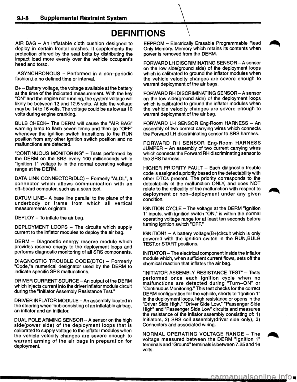
9J-8 Supplemental Restraint System
DEFINITIONS
AIR BAG -An inflatable cloth cushion designed to
deploy in certain frontal crashes. It supplements the
protection offered by the seat belts by distributing the
impact load more evenly over the vehicle occupant's
head and torso.
ASYNCHRONOUS -Performed in a non-periodic
fashion,i.e.no defined time or interval.
B+-Battery voltage, the voltage available at the battery
at the time of the indicated measurement. With the key
"ON" and the engine not running, the system voltage will
likely be between 12 and 12.5 volts. At idle the voltage
may be 14 to 16 volts. The voltage could be as low as 1
0
volts during engine cranking.
BULB
CHECK-The DERM will cause the "AIR BAG"
warning lamp to flash seven times and then go "OFF"
whenever the ignition switch transitions to the RUN
position from any other ignition switch position and no
malfunctions are detected.
"CONTINUOUS MONITORING"-Tests performed by
the DERM on the
SRS every 1 00 milliseconds while
"Ignition
1" voltage is in the normal operating voltage
range at the DERM.
DATA LINK CONNECTOR(DLC)-Formerly "ALDL'', a
connector which allows communication with an
off-board computer, such as a scan
tool.
DATUM LINE-A base line parallel to the plane of the
underbody or frame from which all vertical
measurements originate.
DEPLOY-To inflate the air bag.
DEPLOYMENT
LOOPS - The circuits which supply
current to the inflator modules to deploy the air bag.
DERM -Diagnostic
energy reserve module which
provides reserve energy to the deployment loops and
performs diagnostic monitoring of
all SRS components.
DIAGNOSTIC TROUBLE CODE(DTC) -Formerly
"Code,"a numerical designator used by the DERM to
indicate specific
SRS malfunctions.
DRIVER CURRENT SOURCE-An output of the DERM
which injects current into the driver inflator module circuit
during the "Initiator Assembly Resistance
Test."
DRIVER INFLATOR
MODULE-An assembly located in
the steering wheel hub consisting of an inflatable air bag,
an inflator and an initiator.
DUAL
POLE ARMING SENSOR-A sensor on the high
side(power side) of the deployment loops that is
calibrated to supply voltage to the inflator modules when
the vehicle velocity changes are severe enough to
warrant arming of the air bags in preparation for
deployment.
EEPROM -Electrically Erasable Programmable Read ~
Only Memory. Memory which retains its contents when
power
is removed from the DERM.
FORWARD LH DISCRIMINATING SENSOR-A sensor
on the low side(ground side) of the deployment loops
which is calibrated to ground the inflator modules when
the vehicle velocity changes are severe enough to
warrant deployment of the air bags.
FORWARD RH DISCRIMINATING SENSOR-A sensor
on the low side(ground side) of the deployment loops
which
is calibrated to ground the inflator modules when
the vehicle velocity changes are severe enough
to
warrant deployment of the air bag.
FORWARD LH SENSOR Eng-Room HARNESS-An
assembly of two correct carrying wires which connects
the Forward
LH discriminating sensor to SRS harness.
FORWARD RH SENSOR Eng-Room HARNESS
JUMPER-An assembly of two current carrying wires
which connects the Forward
RH discriminating sensor to
the
SRS harness.
HIGHER PRIORITY FAULT-Each diagnostic trouble
code
is assigned a priority based on the detectability with
other DTCs present. The priority corresponds to the
detectability of the malfunction ONLY, and does NOT
relate to the criticality of the malfunction with respect to ~
deployment or non-deployment under any given
condition.
IGNITION CYCLE -The voltage at the PERM "Ignition
1"
inputs, with ignition switch "ON," is within the normal
operating voltage range for at least ten seconds before
turning ignition switch
"OFF."
IGNITION1
-A battery voltage(B+)circuit which is only
powered with the ignition switch in the RUN,BULB
TEST,or START positions.
INITIATOR-The electrical component inside the inflator
module which, when sufficient current flows, sets off the
chemical reaction that inflates the air bag.
"INITIATOR ASSEMBLY RESISTANCE TEST"-Tests
performed once each ignition cycle when no
malfunctions are detected during "Turn-ON" or
"Continuous Monitoring." This test checks for the correct
DERM configuration for the vehicle, shorts to
"Ignition 1"
in the deployment loops, high resistance or opens in the
"Driver
Side High," "Driver Side Low," "Passenger Side
High"
and "Passenger Side Low" circuits and measures
the resistance of the inflator assembly consisting of: 1)
Initiators, 2) SRS coil assembly(driver side only), 3)
Connectors and associated wiring.
NORMAL OPERATING VOLTAGE RANGE-The ~
voltage measured between the DERM "Ignition 1" ·
terminals and "Ground" terminals is between 7.25 and 16
volts.
•