engine ISUZU TROOPER 1995 Workshop Manual
[x] Cancel search | Manufacturer: ISUZU, Model Year: 1995, Model line: TROOPER, Model: ISUZU TROOPER 1995Pages: 1928
Page 844 of 1928
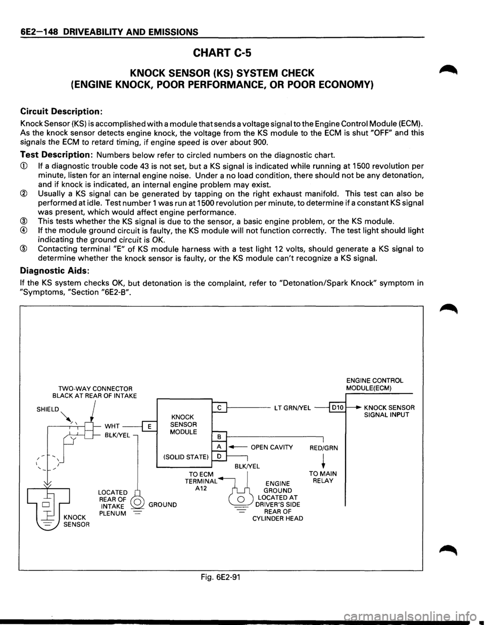
6E2-148 DRIVEABILITY AND EMISSIONS
CHART C-5
KNOCK SENSOR (KS) SYSTEM CHECK
(ENGINE KNOCK, POOR PERFORMANCE, OR POOR ECONOMY)
Circuit Description:
Knock Sensor (KS) is accomplished with a module that sends a voltage signal to the Engine Control Module {ECM).
As the knock sensor detects engine knock, the
voltage from the KS module to the ECM is shut "OFF" and this
signals the ECM to retard timing, if engine speed is over about 900.
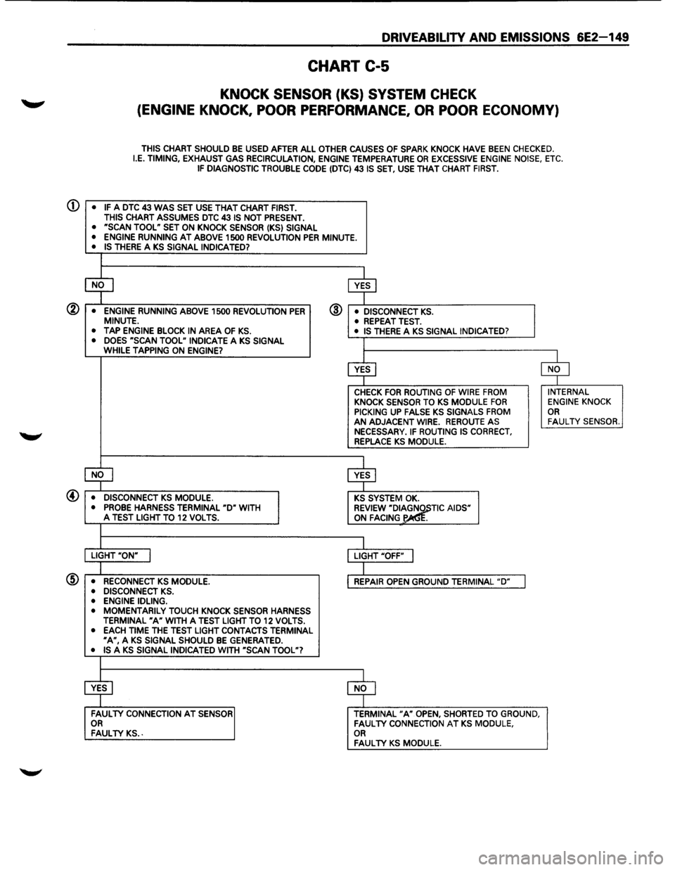
Test Description: Numbers below refer to circled numbers on the diagnostic chart.
CD If a diagnostic trouble code 43 is not set, but a KS signal is indicated while running at 1500 revolution per
minute,
listen for an internal engine noise. Under a no load condition, there should not be any detonation,
and
if knock is indicated, an internal engine problem may exist.
@ Usually a KS signal can be generated by tapping on the right exhaust manifold. This test can also be
performed at idle. Test number 1 was run at 1500 revolution per minute, to determine if a constant KS signal
was present, which would affect engine performance.
® This tests whether the KS signal is due to the sensor, a basic engine problem, or the KS module.
@ If the module ground circuit is faulty, the KS module will not function correctly. The test light should light
indicating the ground circuit is OK.
@ Contacting terminal "E" of KS module harness with a test light 12 volts, should generate a KS signal to
determine whether the knock sensor is faulty, or the KS module can't recognize a KS signal.
Diagnostic Aids:
If the KS system checks OK, but detonation is the complaint, refer to "Detonation/Spark Knock" symptom in
"Symptoms, "Section "6E2-8".
/ I
'
TWO-WAY CONNECTOR BLACK AT REAR OF INTAKE
I
-WHT
BLK!YEL
LOCATED REAR OF 0 INTAKE PLENUM
1------LT GRN/YEL
KNOCK
SENSOR
MODULE
BLK!YEL
GROUND
TOECM~ TERMINAL ENGINE A12 GROUND
0 LOCATEDAT _ DRIVER'S SIDE REAR OF CYLINDER HEAD
Fig. 6E2-91
RED/GRN
+ TO MAIN RELAY
ENGINE CONTROL
MODULE(ECM)
KNOCK SENSOR
SIGNAL INPUT
..
Page 845 of 1928
DRIVEABILITV AND EMISSIONS 6E2-149
CHART C-5
KNOCK SENSOR (KS) SYSTEM CHECK
(ENGINE KNOCK, POOR PERFORMANCE, OR POOR ECONOMY)
THIS CHART SHOULD BE USED AFTER ALL OTHER CAUSES OF SPARK KNOCK HAVE BEEN CHECKED. I.E. TIMING, EXHAUST GAS RECIRCULATION, ENGINE TEMPERATURE OR EXCESSIVE ENGINE NOISE, ETC. IF DIAGNOSTIC TROUBLE CODE (DTC) 431S SET, USE THAT CHART FIRST.
$ $
• ENGINE RUNNING ABOVE 1500 REVOLUTION PER @ • DISCONNECT KS. MINUTE. • REPEAT TEST. • TAP ENGINE BLOCK IN AREA OF KS. • IS THERE A KS SIGNAL INDICATED? • DOES ~scAN TOOL" INDICATE A KS SIGNAL I WHILE TAPPING ON ENGINE?
$ $
CHECK FOR ROUTING OF WIRE FROM INTERNAL KNOCK SENSOR TO KS MODULE FOR ENGINE KNOCK PICKING UP FALSE KS SIGNALS FROM OR AN ADJACENT WIRE. REROUTE AS FAUL TV SENSOR. NECESSARY. IF ROUTING IS CORRECT, REPLACE KS MODULE.
l4J $
• DISCONNECT KS MODULE. KS SYSTEM OK. • PROBE HARNESS TERMINAL "D" WITH REVIEW "DI~TIC AIDS" A TEST LIGHT TO 12 VOLTS. ON FACING .
I LIGHT "ON" I LIGHT "OFF" I
I • RECONNECT KS MODULE. REPAIR OPEN GROUND TERMINAL "D" J • DISCONNECT KS.
@
• ENGINE IDLING. • MOMENTARILY TOUCH KNOCK SENSOR HARNESS TERMINAL "A" WITH A TEST LIGHT TO 12 VOLTS. • EACH TIME THE TEST LIGHT CONTACTS TERMINAL ~A", A KS SIGNAL SHOULD BE GENERATED. • IS A KS SIGNAL INDICATED WITH "SCAN TOOL"?
$ $
FAULTY CONNECTION AT SENSOR TERMINAL "A" OPEN, SHORTED TO GROUND, OR FAULTY CONNECTION AT KS MODULE, FAULTY KS .. OR FAUL TV KS MODULE.
Page 847 of 1928
DRIVEABILITY AND EMISSIONS 6E2-151
SECTION C-7
EXHAUST GAS RECIRCULATION (EGR) SYSTEM
CONTENTS
GENERAL DESCRIPTION ................. 6E2-151
Operation . . . . . . . . . . . . . . . . . . . . . . . . . . . 6E2-151
Exhaust Gas
Recirculation (EGR) Valve
Check . .
. . . . . . . . . . . . . . . . . . . . . . . . . . 6E2-152
Exhaust Gas
Recirculation (EGR)
Backpressure Transducer (BPT) Check 6E2-152
Exhaust Gas
Recirculation (EGR)
Vacuum Switch Valve (VSV) Solenoid
Check . .
. . . . . . . . . . . . . . . . . . . . . . . . . . 6E2-152
DIAGNOSIS ........................... 6E2-153
ON-VEHICLE SERVICE .................... 6E2-153
Exhaust Gas
Recirculation (EGR)
Manifold Passage ................... 6E2-153
Exhaust Gas
Recirculation (EGR)
Valve Replacement .................. 6E2-153
Exhaust
Gas Recirculation (EGR)
Backpressure Transducer (BPT)
Replacement ....................... 6E2-153
Exhaust Gas
Recirculation (EGR)
Vacuum Switch Valve (VSV) Replacement . 6E2-153
CHART C-7A Exhaust Gas
Recirculation (EGR)
System Check ...................... 6E2-154
GENERAL DESCRIPTION
The Exhaust Gas Recirculation (EGR) System controls
the formation of NOx (Oxides of Nitrogen) Emissions
by
recirculating the exhaust gases into the combustion
chamber. This is done through the intake
manifold.
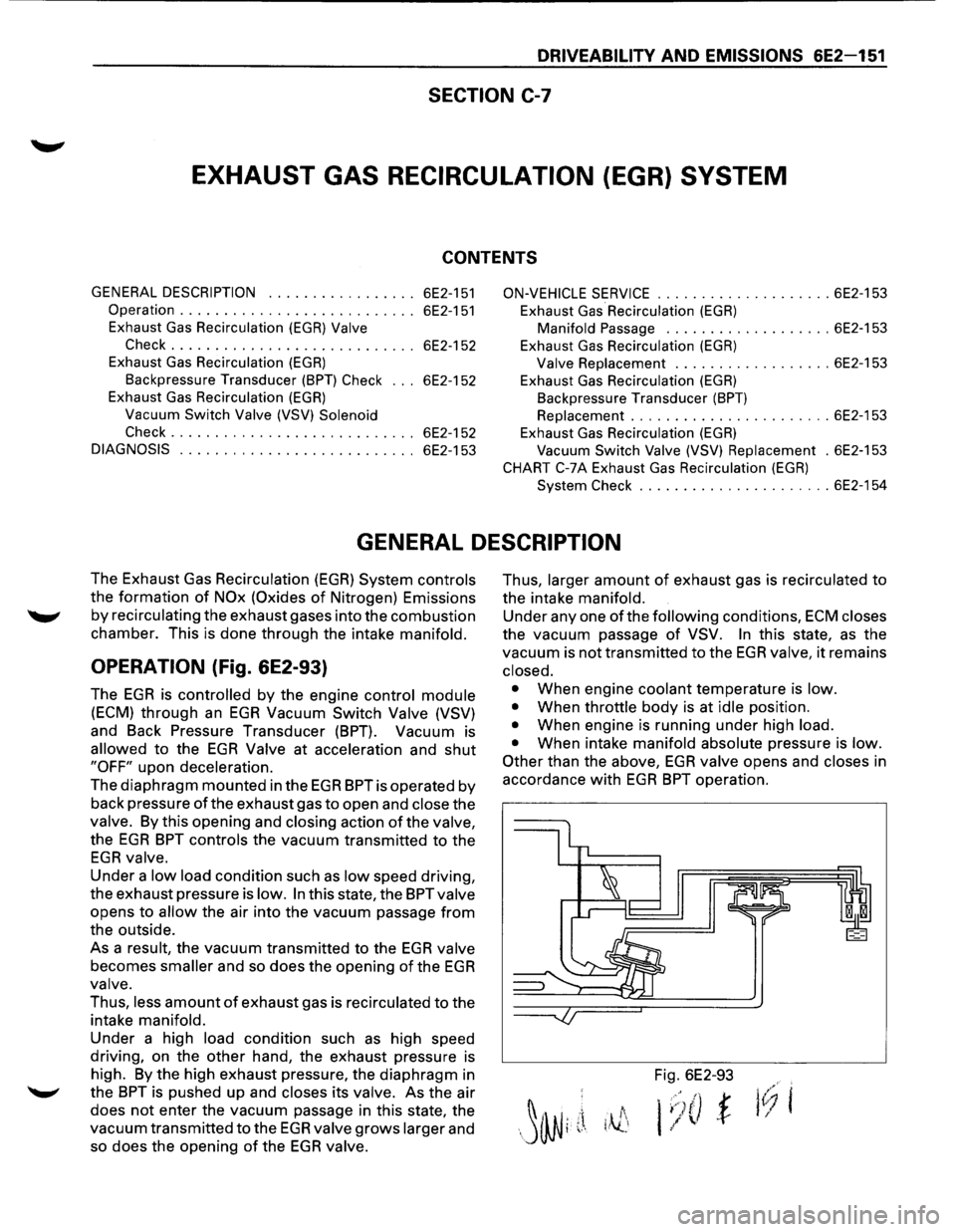
OPERATION (Fig. 6E2-93)
The EGR is controlled by the engine control module
(ECM) through an EGR Vacuum Switch Valve (VSV)
and Back Pressure Transducer (BPT). Vacuum is
allowed to the EGR Valve at acceleration and shut
"OFF" upon deceleration.
The diaphragm mounted in the EGR BPT is operated by
back pressure
of the exhaust gas to open and close the
valve. By this opening and closing action of the valve,
the EGR BPT controls the vacuum transmitted to the
EGR valve.
Under
a low load condition such as low speed driving,
the exhaust pressure is
low. In this state, the BPTvalve
opens to allow the air into the vacuum passage from
the outside.
As a
result, the vacuum transmitted to the EGR valve
becomes smaller and so does the opening of the EGR
valve.
Thus, less amount of exhaust gas is recirculated to the
intake
manifold.
Under
a high load condition such as high speed
driving, on the
other hand, the exhaust pressure is
high. By the high exhaust pressure, the diaphragm in
the
BPT is pushed up and closes its valve. As the air
does
not enter the vacuum passage in this state, the
vacuum transmitted
to the EGR valve grows larger and
so does the opening
of the EGR valve.
Thus, larger amount of exhaust gas is recirculated to
the intake manifold.
Under
any one ofthe following conditions, ECM closes
the vacuum passage of VSV. In this state, as the
vacuum is not transmitted
to the EGR valve, it remains
closed.
•
When engine coolant temperature is low.
•
When throttle body is at idle position.
• When engine is running under high load.
•
When intake manifold absolute pressure is low.
Other
than the above, EGR valve opens and closes in
accordance
with EGR BPT operation.
Fig. 6E2-93
i
.
,::·)I)' t
/
..f-l
Page 848 of 1928
6E2-152 DRIVEABILITV AND EMISSIONS
EXHAUST GAS RECIRCULATION (EGR)
VALVE
CHECK
1. Engine operating a normal temperature 60oC
(120°F).
2. Place finger on Exhaust Gas Recirculation (EGR)
valve diaphragm and accelerate engine,
diaphragm
should move.
3. Disconnect vacuum hose from EGR valve.
4. Apply 10" inches of vacuum using a vacuum
pump to valve with finger on diaphragm. It should
move and engine may stall.
5. If valve passes the above test use CHART C-7 A. If
valve fails, replace valve.
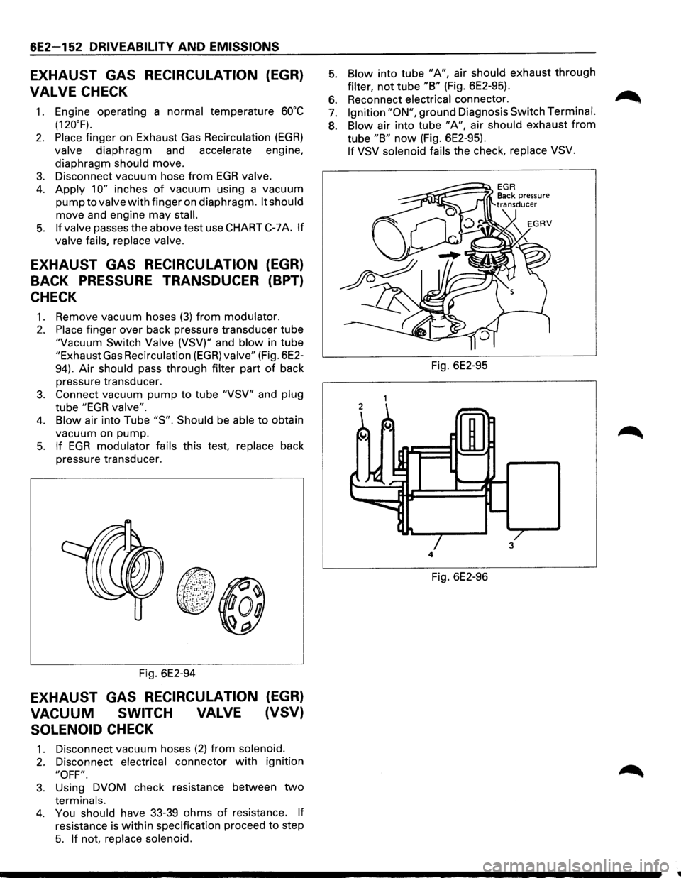
EXHAUST GAS RECIRCULATION (EGR)
BACK PRESSURE TRANSDUCER (BPT)
CHECK
1. Remove vacuum hoses (3) from modulator.
2. Place finger over back pressure transducer tube
"Vacuum Switch Valve (VSV)" and blow in tube
"Exhaust Gas Recirculation (EGR) valve" (Fig. 6E2-
94).
Air should pass through filter part of back
pressure transducer.
3. Connect vacuum pump to tube "VSV" and plug
tube "EGR valve".
4. Blow air into Tube "S". Should be able to obtain
vacuum on pump.
5. If EGR modulator fails this test, replace back
pressure transducer.
Fig. 6E2-94
EXHAUST GAS RECIRCULATION (EGR)
VACUUM SWITCH VALVE (VSV)
SOLENOID
CHECK
1. Disconnect vacuum hoses (2) from solenoid.
2. Disconnect electrical connector with ignition
"OFF".
3. Using DVOM check resistance between two
terminals.
4. You should have 33-39 ohms of resistance. If
resistance is within specification proceed to step
5. If not, replace solenoid.
5. Blow into tube "A", air should exhaust through
filter, not tube "B" (Fig. 6E2-95).
6. Reconnect electrical connector. ~
7. Ignition "ON", ground Diagnosis Switch Terminal.
8. Blow air into tube "A", air should exhaust from
tube "B" now (Fig. 6E2-95).
If VSV solenoid fails the check, replace VSV.
Fig. 6E2-95
4
Fig. 6E2-96
•
Page 849 of 1928
DRIVEABILITV AND EMISSIONS 6E2-153
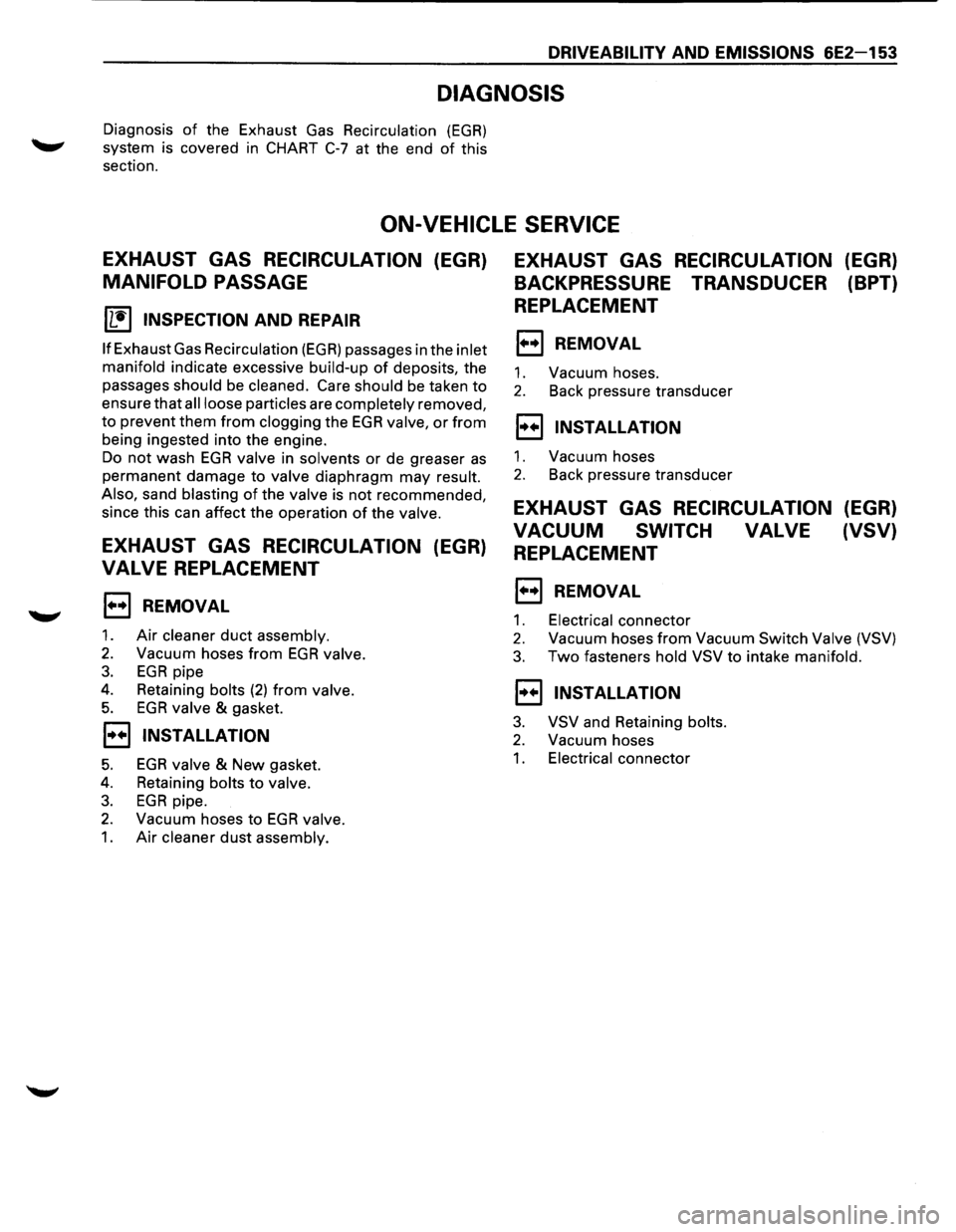
DIAGNOSIS
Diagnosis of the Exhaust Gas Recirculation (EGR)
system is covered in CHART C-7 at the end of this
section.
ON-VEHICLE SERVICE
EXHAUST GAS RECIRCULATION (EGR)
MANIFOLD PASSAGE
[!j INSPECTION AND REPAIR
If Exhaust Gas Recirculation (EGR) passages in the inlet
manifold indicate excessive build-up
of deposits, the
passages should
be cleaned. Care should be taken to
ensure that
all loose particles are completely removed,
to prevent them
from clogging the EGR valve, or from
being ingested into the engine.
Do not wash EGR valve in solvents or de greaser as
permanent damage to valve diaphragm may result.
Also, sand blasting
of the valve is not recommended,
since this can affect the operation
of the valve.
EXHAUST GAS RECIRCULATION (EGR)
VALVE REPLACEMENT
1••1 REMOVAL
1. Air cleaner duct assembly.
2. Vacuum hoses from EGR valve.
3. EGR pipe
4. Retaining bolts (2) from valve.
5. EGR valve & gasket.
1••1 INSTALLATION
5. EGR valve & New gasket.
4. Retaining bolts to valve.
3. EGR pipe.
2. Vacuum hoses to EGR valve.
1. Air cleaner dust assembly.
EXHAUST GAS RECIRCULATION (EGR)
BACKPRESSURE TRANSDUCER (BPT)
REPLACEMENT
1••1 REMOVAL
1. Vacuum hoses.
2. Back pressure transducer
1••1 INSTALLATION
1. Vacuum hoses
2. Back pressure transducer
EXHAUST GAS RECIRCULATION (EGR)
VACUUM SWITCH VALVE (VSV)
REPLACEMENT
1••1 REMOVAL
1. Electrical connector
2. Vacuum hoses from Vacuum Switch Valve (VSV)
3. Two fasteners hold VSV to intake manifold.
1••1 INSTALLATION
3. VSV and Retaining bolts.
2. Vacuum hoses
1. Electrical connector
Page 850 of 1928
6E2-154 DRIVEABILITY AND EMISSIONS
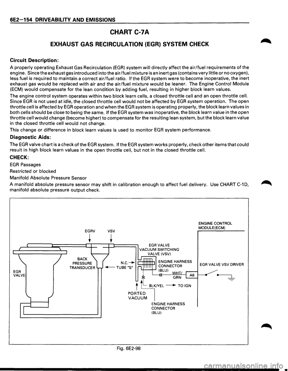
CHART C-7A
EXHAUST GAS RECIRCULATION (EGR) SYSTEM CHECK
Circuit Description:
A properly operating Exhaust Gas Recirculation (EGR) system will directly affect the air/fuel requirements of the
engine. Since the exhaust gas introduced into the air/fuel mixture is
an inert gas (contains very little or no oxygen),
less fuel is required
to maintain a correct air/fuel ratio. If the EGR system were to become inoperative, the inert
exhaust gas
would be replaced with air and the air/fuel mixture would be leaner. The Engine Control Module
(ECM) would compensate for the lean condition by adding fuel, resulting in higher block learn values.
The engine control system operates within
two block learn cells, a closed throttle cell and an open throttle cell.
Since EGR is not used at idle, the closed throttle cell would not be affected by EGR system operation. The open
throttle
cell is affected by EGR operation and when the EGR system is operating properly, the block learn values in
both
cells should be close to being the same. If the EGR system was inoperative, the block learn value in the open
throttle
cell would change (become higher) to compensate for the resulting lean system, but the block learn value
in the closed throttle
cell would not change.
This change or difference in block learn values is used to monitor
EGR system performance.
Diagnostic Aids:
The EGR valve chart is a check of the EGR system. If the EGR system works properly, check other items that could
result in high block learn values in the open throttle
cell, but not in the closed throttle cell.
CHECK:
EGR Passages
Restricted
or blocked
Manifold Absolute Pressure Sensor
A manifold absolute pressure sensor may shift in calibration enough to affect fuel delivery. Use CHART
C-1 0,
manifold absolute pressure output check.
EGR VALVE
EGRV
+
BACK
PRESSURE
TRANSDUCER
vsv
+ EGRVALVE VACUUM SWITCHING
VALVE (VSV)
ENGINE HARNESS
CONNECTOR
'+--+-' ( BLU)
GRN AB
t tt BL~L ---+ TO IGN
PORTED VACUUM
Fig. 6E2-98
ENGINE HARNESS
CONNECTOR
(BLU)
ENGINE CONTROL
MODULE(ECM)
EGR VALVE VSV DRIVER
•
Page 851 of 1928
DRIVEABILITY AND EMISSIONS 6E2-155
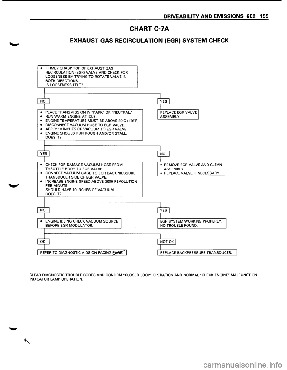
CHART C-7A
EXHAUST GAS RECIRCULATION (EGR) SYSTEM CHECK
• FIRMLY GRASP TOP OF EXHAUST GAS
RECIRCULATION (EGR} VALVE AND CHECK FOR LOOSENESS BY TRYING TO ROTATE VALVE IN BOTH DIRECTIONS. IS LOOSENESS FELT?
• PLACE TRANSMISSION IN "PARK" OR "NEUTRAL."
• RUN WARM ENGINE AT IDLE. • ENGINE TEMPERATURE MUST BE ABOVE so·c (176.F}. • DISCONNECT VACUUM HOSE TO EGR VALVE. • APPLY 10 INCHES OF VACUUM TO EGR VALVE. • ENGINE SHOULD RUN ROUGH AND/OR STALL.
DOES IT?
• CHECK FOR DAMAGE VACUUM HOSE FROM THROTILE BODY TO EGR VALVE. • CONNECT VACUUM GAGE TO EGR BACKPRESSURE
TRANSDUCER SIDE OF EGR VALVE. • INCREASE ENGINE SPEED ABOVE 2000 REVOLUTION PER MINUTE. SHOULD HAVE 10 INCHES OF VACUUM. DOES IT?
• ENGINE IDLING CHECK VACUUM SOURCE BEFORE EGR MODULATOR.
• REMOVE EGR VALVE AND CLEAN
ASSEMBLY.
•
REPLACE VALVE IF NECESSARY.
EGR SYSTEM WORKING PROPERLY. NO TROUBLE FOUND.
REPLACE
BACKPRESSURE TRANSDUCER.
CLEAR DIAGNOSTIC
TROUBLE CODES AND CONFIRM "CLOSED LOOP" OPERATION AND NORMAL "CHECK ENGINE" MALFUNCTION
INDICATOR LAMP OPERATION.
Page 853 of 1928
DRIVEABILITY AND EMISSIONS 6E2-157
SECTION C-8
SHIFT INDICATOR LIGHT (MIT ONLY)
CONTENTS
General Description . . . . . . . . . . . . . . . . . . . . . 6E2-157 Diagnosis ............................. 6E2-157
Purpose ............................ 6E2-157 Transmission Switch Functional Check ..... 6E2-157
Operation . . . . . . . . . . . . . . . . . . . . . . . . . . . 6E2-157 Clutch Switch Functional Check ........... 6E2-157
Chart C-8 Manual Transmission (M/T)
Shift Light ........................... 6E2-158
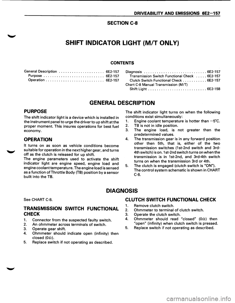
GENERAL DESCRIPTION
PURPOSE
The shift indicator light is a device which is installed in
the instrument
panel to urge the driver to up shiftatthe
proper moment. This insures operations for best fuel
economy.
OPERATION
It turns on as soon as vehicle conditions become
suitable for operation in the next higher gear, and turns
off as the clutch is released for up shift.
The engine parameters used
to activate the shift
indicator
light are engine speed, engine load and
engine
coolant temperature. The engine load is sensed
as a function of Throttle Body (TB) position by a sensor
built into the TB. The
shift indicator
light turns on when the following
conditions exist simultaneously:
1. Engine coolant temperature is hotter than -s·c.
2. TB is not in idle position.
3. The engine load, is not greater than the
predetermined
values.
4. The transmission gear is in any forward position
other then 5th, that is, either
of the two
transmission switches (1st-2nd switch and 3rd-
4th switch) is on. 1st-2nd switch turns on
when the
transmission is in 1st-2nd, and 3rd-4th switch
turns on when the transmission 3rd
or 4th.
5. The clutch is engaged (clutch switch is "ON").
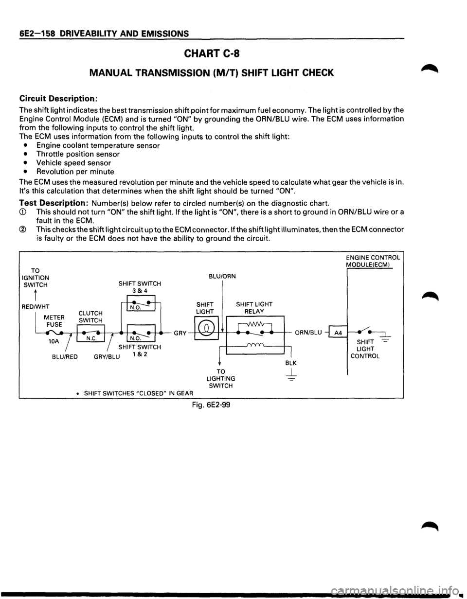
The control system schematic is shown in CHART
C-8.
DIAGNOSIS
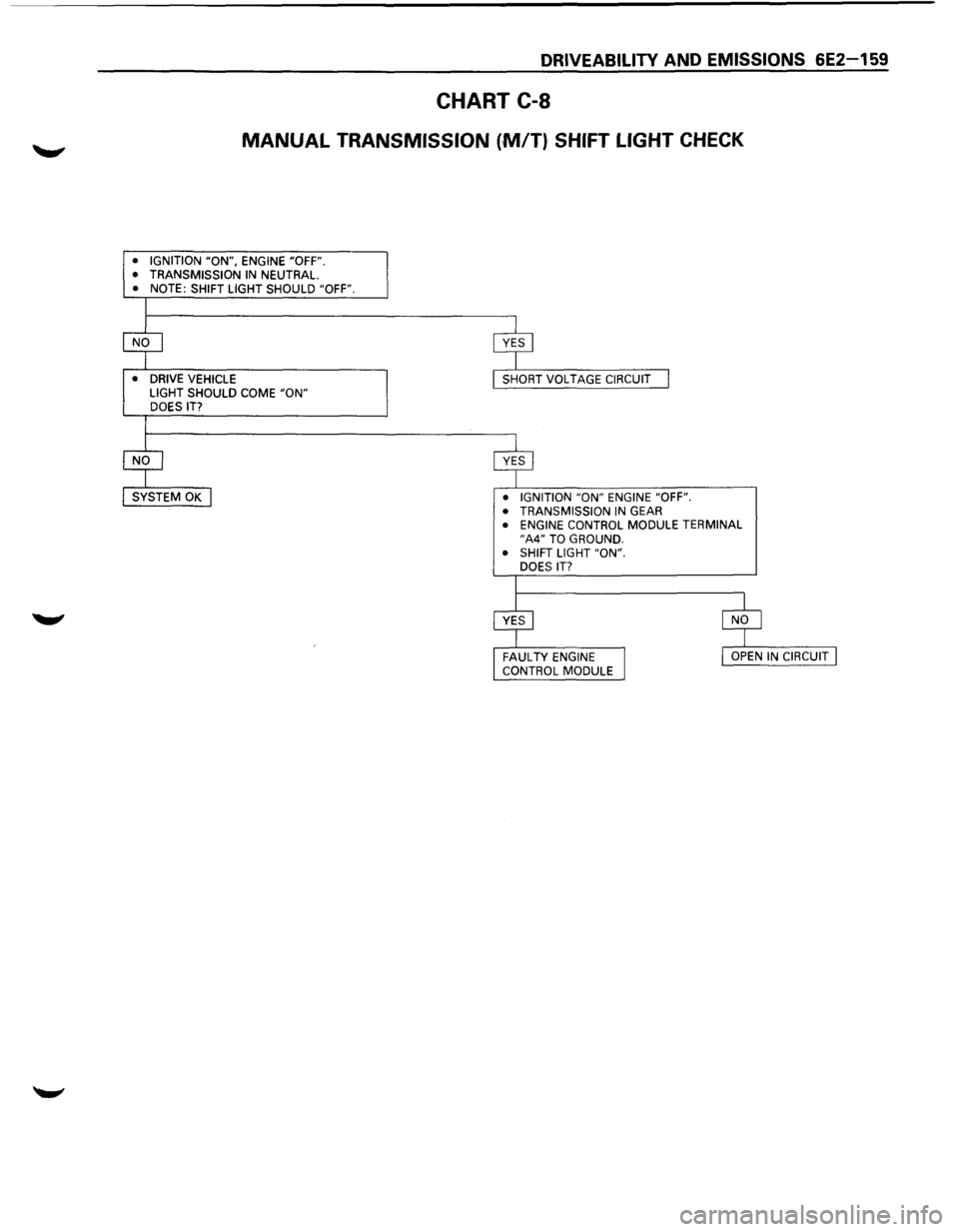
See CHART C-8.
TRANSMISSION SWITCH FUNCTIONAL
CHECK
1. Connector from the suspected faulty switch.
2. An ohmmeter across terminals of switch.
3. Operate gear shift.
4. Ohmmeter should indicate open (infinity) then
closed (00).
5. Replace switch if not operating as described.
CLUTCH SWITCH FUNCTIONAL CHECK
1. Remove clutch switch.
2. Ohmmeter to terminal of clutch switch.
3. Operate the clutch switch.
4. Ohmmeter should read "closed" (00) then
"open" (infinity) when clutch switch is pressed.
5. Replace switch if not operating as described.
Page 854 of 1928
6E2-158 DRIVEABILITV AND EMISSIONS
CHART C-8
MANUAL TRANSMISSION (M/T) SHIFT LIGHT CHECK
Circuit Description:
The shift light indicates the best transmission shift point for maximum fuel economy. The light is controlled by the
Engine Control Module
(ECM) and is turned "ON" by grounding the ORN/BLU wire. The ECM uses information
from the following inputs to control the shift light.
The
ECM uses information from the following inputs to control the shift light:
• Engine coolant temperature sensor
• Throttle position sensor
• Vehicle speed sensor
• Revolution per minute
The
ECM uses the measured revolution per minute and the vehicle speed to calculate what gear the vehicle is in.
It's this calculation that determines when the shift light should be turned "ON".
Test Description: Number(s) below refer to circled number(s) on the diagnostic chart.
ECM.
® This checks the shift light circuit up to the ECM connector .If the shift light illuminates, then the ECM connector
is faulty
or the ECM does not have the ability to ground the circuit.
TO
IGNITION SWITCH
t
BLU/RED GRY/BLU
•
SHIFT SWITCHES #CLOSED" IN GEAR
BLU/ORN
SHIFT SHIFT LIGHT
LIGHT
RELAY
TO
LIGHTING SWITCH
Fig. 6E2-99
ENGINE CONTROL
MODULE(ECMl
SHIFT
LIGHT
CONTROL
Page 855 of 1928
DRIVEABILITY AND EMISSIONS 6E2-159
CHART C-8
MANUAL TRANSMISSION (,MfT) SHIFT LIGHT CHECK
• IGNITION "ON", ENGINE "OFF".
• TRANSMISSION IN NEUTRAL. • NOTE: SHIFT LIGHT SHOULD "OFF".
•
DRIVE VEHICLE
LIGHT SHOULD COME "ON" DOES IT?
• IGNITION
"ON" ENGINE "OFF".
• TRANSMISSION IN GEAR • ENGINE CONTROL MODULE TERMINAL "A4" TO GROUND.
• SHIFT LIGHT "ON".
DOES
IT?