engine ISUZU TROOPER 1995 Workshop Manual
[x] Cancel search | Manufacturer: ISUZU, Model Year: 1995, Model line: TROOPER, Model: ISUZU TROOPER 1995Pages: 1928
Page 884 of 1928
7A-12 AUTOMATIC TRANSMISSION (4L30-E)
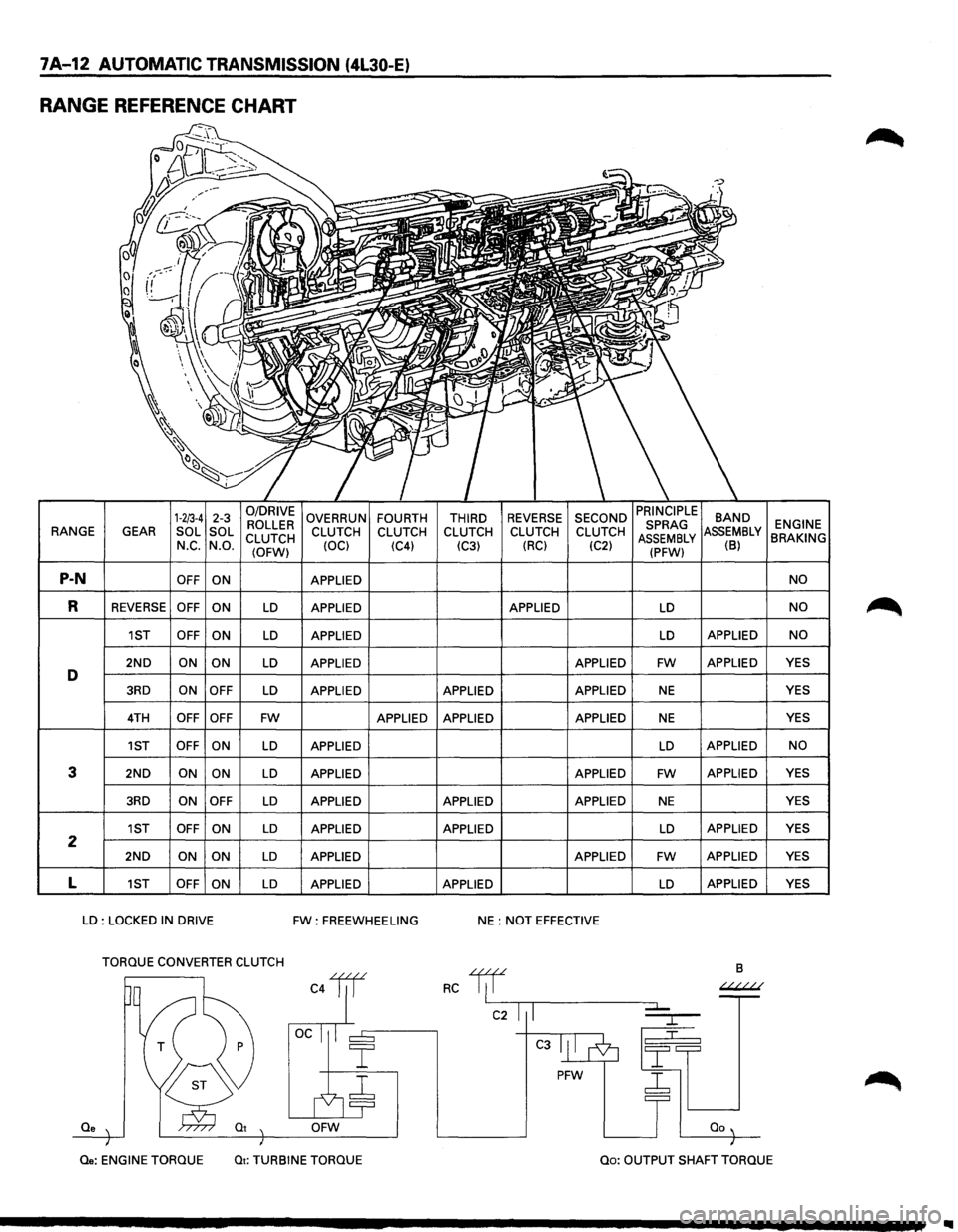
RANGE REFERENCE CHART
1-2/3-4 2-3 0/DRIVE OVERRUN FOURTH THIRD REVERSE SECOND BAND ROLLER ENGINE RANGE
GEAR SOL
SOL
CLUTCH CLUTCH
CLUTCH CLUTCH CLUTCH CLUTCH MBLY BRAKING N_c. N.O.
(OFW) (OCl
(C4)
(C3) (RC)
(C2) (B)
P-N OFF
ON APPLIED NO
R REVERSE OFF
ON LD APPLIED APPLIED LD NO
1ST OFF
ON LD APPLIED LD APPLIED NO
2ND ON ON LD APPLIED APPLIED FW APPLIED YES D 3RD ON
OFF LD APPLIED APPLIED APPLIED NE YES
4TH OFF OFF FW APPLIED APPLIED APPLIED NE YES
1ST OFF ON
LD APPLIED LD APPLIED NO
3 2ND ON ON LD APPLIED APPLIED FW APPLIED
YES
3RD ON OFF LD APPLIED APPLIED APPLIED NE YES
1ST OFF
ON LD APPLIED APPLIED LD APPLIED YES 2 2ND ON
ON LD APPLIED APPLIED FW APPLIED YES
L 1ST OFF
ON LD APPLIED APPLIED LD APPLIED
YES
LD : LOCKED IN DRIVE FW: FREEWHEELING NE : NOT EFFECTIVE
TORQUE CONVERTER CLUTCH
B
C4lil RC 1/f ~
C2 I I
C3
PFW ~
Qe OFW
Qe: ENGINE
TORQUE Qt: TURBINE TORQUE Qo: OUTPUT SHAFT TORQUE
Page 885 of 1928
AUTOMATIC TRANSMISSION (4L30-E) 7A-13
NORMAL OPERATION OF 1994-95 4L30-E TRANSMISSION
1. TORQUE CONVERTER CLUTCH (TCC)
APPLICATION CONDITIONS:
Engine coolant temperature must be above 70°C
(158°F).
Moreover, TCC is ON in 2nd gear during kick down
operation when engine coolant temperature is
above
70°C (158°F).
Also,
TCC is always ON in 2nd, 3rd & 4th gear when
transmission oil temperature is above 140°C
(284°F).
2. ATF WARNING LAMP
The ATF warning lamp will be constantly on (not
flashing) if the transmission oil temperature is
above
145°C (293°F).
The ATF warning lamp goes off again when the
transmission
oil temperature is below 125°C
(257°F).
3. SPECIAL SHIFT PATTERN WHEN THE
ENGINE IS COLD:
A special shift pattern is activated when the engine
coolant temperature is below 70°C (158°F). (3-4
shifts
for example are delayed for small throttle
openings and will occur a few MPH higher)
4. SHIFT ALTERATION WITH TECH1
DIAGNOSTIC TOOL CONNECTED:
Shifts will be harsh when TECH1 is connected to
TCM: Connection of TECH1 automatically forces
maximum line pressure during shifts only.
Page 891 of 1928
AUTOMATIC TRANSMISSION (4l30-E) 7A-19
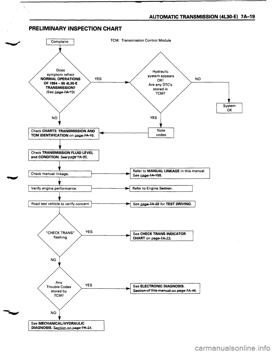
PRELIMINARY INSPECTION CHART
Does symptom reflect
NORMAL OPERATIONS
OF 1994 -95 4L30·E
TRANSMISSION?
(See p.age-1-Ac13)
YES
Check CHART3: TRANSMISSION AND TCM IDENTIFICATION on page-~n.
Check TRANSMISSION FLUID LEVEL and CONDITION. See--page"'7A'•2'0.
Check manual linkage. TCM:
Transmission Control Module
Hydraulic system appears OK!
Are any DTC's stored in TCM?
NO
Refer to MANUAL LINKAGE in this manual.
See~.
Ll_v_e_rify_e_n_g_in_e..:.p_e~rf_or_m_a_n_c_e. ___ l--------1•~1 Refer to Engine Seeticm.
Road
test vehicle to verify concern l----------;..f~s~e;;e-;:ga;;;:;:ge~7.A:o.~2i2f;fo;;r~TiE:SsTTDD~RmlvliiNNiGG~.l
UCHECK TRANS"
flashing >--Y-ES ________ ~ See CHECK TRANS INDICATOR
CHART
on page 7A-23.
Any
Trouble Codes stored by TCM?
YES
See
MECHANICAL/HYDRAULIC DIAGNOSIS.~.
See ELECTRONIC DIAGNOSIS. ~r tliis nusnllal on-JH!ge 7A 45.
Page 892 of 1928
7 A-20 AUTOMATIC TRANSMISSION (4L30-E)
CHECKING TRANSMISSION FLUID
LEVEL AND CONDITION
Checking fluid level and condition (color and odor)
at
regular intervals will provide early diagnosis
information about the transmission. This inform
ation may be used to correct a condition that, if not
detected early, could result in major transmission
repairs.
IMPORTANT: When new, automatic transmission
fluid is red in color. As the vehicle is driven, the
transmission
fluid will begin to look darker in color.
The
color may eventually appear light brown.
A DARK
brown color with burnt odor may indicate
excessive
fluid deterioration and signal a need for
fluid change.
FLUID LEVEL
When adding
or changing fluid, use only DEXRON
®-Ill.
Refer to the Maintenance and Lubrication (Section 0
of this manual) for maintenance information and
servicing
interval.
\f CAUTION: DO NOT OVERFILL
Overfilling will cause foaming, loss ~f fluid,
abnormal shifting and possible damage to
the transmission.
1. Start engine and drive vehicle until normal AfT
oil operating temperature is reached:
NOTE: The automatic transmission fluid level
must be checked with the vehicle at normal
A/T oil operating temperature: 75 TO 85°C
(167 TO 185°F) MEASURED WITH TECH1 SCAN
TOOL.
Temperature will greatly affect transmission
fluid level.
If the vehicle is not at normal AfT oil operating
temperature and the proper checking
procedures are
not followed, the result could
be a false reading of the fluid level indicator
and
an incorrect adjustment of the fluid level.
2. Park vehicle on level ground.
3. Move gear selector to "Park".
4. Apply parking brake and block wheels.
5. Allow vehicle to idle for 3 minutes with all
accessories turned off.
6. Check fluid level with engine running at idle:
Fluid should
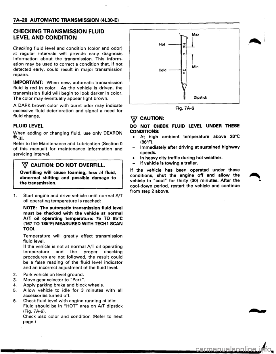
be in "HOT" area on AfT dipstick
(Fig. 7A-6).
Check also color and condition (Refer to next
page.)
Hot
Cold ---IIU 0
0
Min
Dipstick
Fig. 7A-6
\f CAUTION:
DO NOT CHECK FLUID LEVEL UNDER THESE
CONDITIONS: •
At high ambient temperature above 30°C
(86°F).
Immediately after driving at sustained highway
speeds.
• In heavy city traffic during hot weather.
If vehicle is towing a trailer.
If the vehicle has been operated under these
conditions,
shut the engine off and allow the
vehicle to "cool" for thirty (30) minutes. After the
cool-down period, restart the vehicle and continue
from step 2 above.
'~I
......
Page 894 of 1928
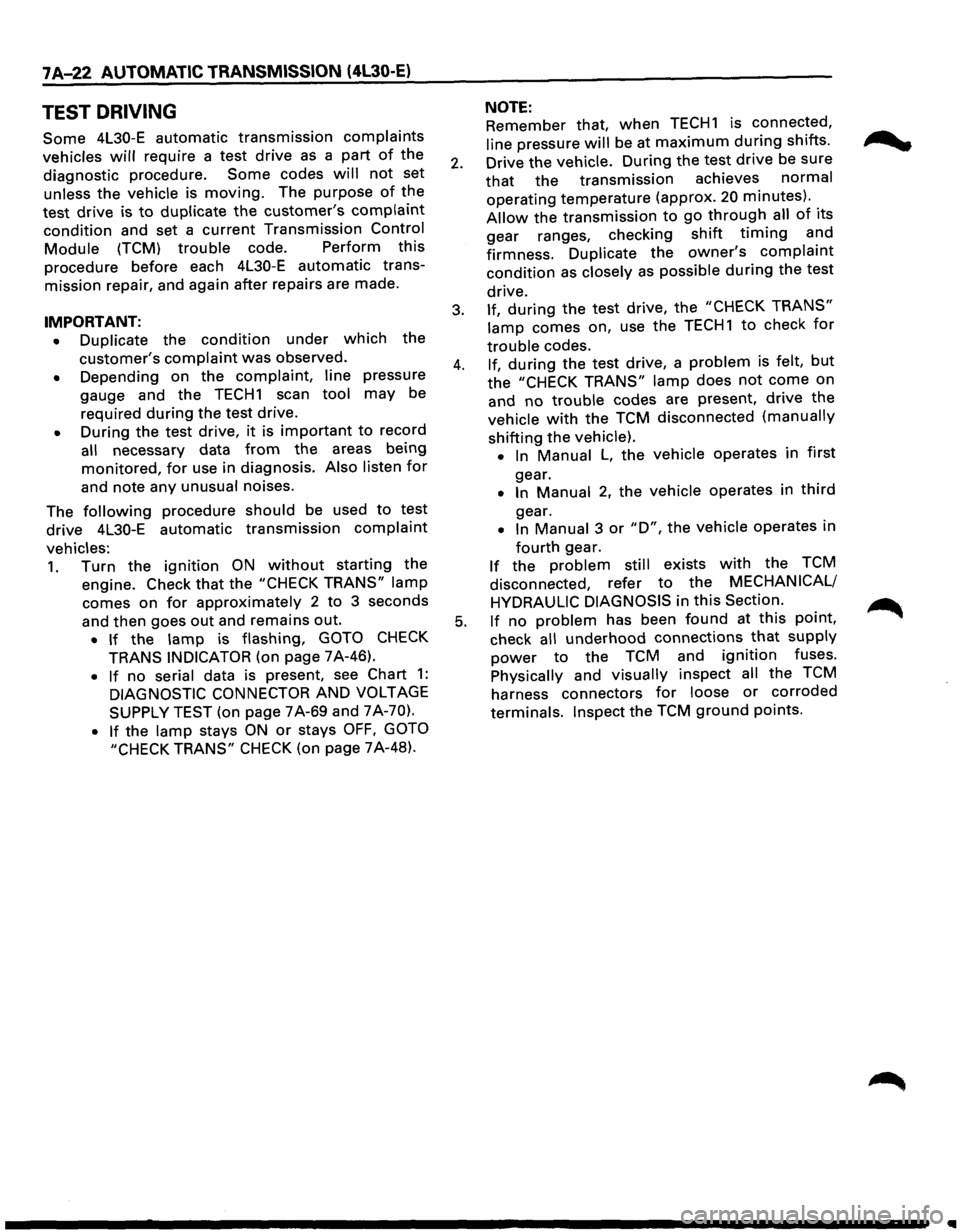
7 A-22 AUTOMATIC TRANSMISSION (4l30-E)
TEST DRIVING
Some 4L30-E automatic transmission complaints
vehicles will require a test drive as a part of the
diagnostic procedure.
Some codes will not set
unless the vehicle is moving. The purpose of the
test
drive is to duplicate the customer's complaint
condition and set a current Transmission Control
Module (TCM) trouble code. Perform this
procedure before each 4L30-E automatic trans
mission repair, and again after repairs are made.
IMPORTANT:
• Duplicate the condition under which the
customer's complaint was observed.
• Depending on the complaint, line pressure
gauge and the
TECH1 scan tool may be
required
during the test drive.
• During the test drive, it is important to record
all necessary data from the areas being
monitored, for use in diagnosis. Also listen for
and note any unusual noises.
The
following procedure should be used to test
drive 4L30-E automatic
transmission complaint
vehicles:
1. Turn the ignition ON without starting the
engine. Check
that the "CHECK TRANS" lamp
comes on for approximately 2 to 3 seconds
and then goes
out and remains out.
• If the lamp is flashing, GOTO CHECK
TRANS INDICATOR (on page 7A-46).
• If no serial data is present, see Chart 1:
DIAGNOSTIC CONNECTOR AND VOLTAGE
SUPPLY TEST (on page 7A-69 and 7A-70).
• If the lamp stays ON or stays OFF, GOTO
"CHECK TRANS"
CHECK (on page 7A-48).
NOTE:
Remember that, when TECH1 is connected,
line pressure will be at maximum during shifts.
2. Drive the vehicle. During the test drive be sure
that the transmission achieves normal
operating temperature (approx. 20 minutes) ..
Allow the transmission to go through all of 1ts
gear ranges, checking shift timing and
firmness.
Duplicate the owner's complaint
condition as closely as possible during the test
drive.
3. If, during the test drive, the "CHECK TRANS"
lamp comes on, use the TECH1 to check for
trouble codes.
4. If, during the test drive, a problem is felt, but
the "CHECK TRANS" lamp does not come on
and
no trouble codes are present, drive the
vehicle with the TCM disconnected (manually
shifting the vehicle).
•
In Manual L, the vehicle operates in first
gear.
• In Manual 2, the vehicle operates in third
gear.
• In Manual 3 or "D", the vehicle operates in
fourth gear.
If the problem still exists with the TCM
disconnected, refer
to the MECHANICAL/
HYDRAULIC DIAGNOSIS
in this Section.
5. If no problem has been found at this point,
check
all underhood connections that supply
power to the TCM and ignition fuses.
Physically and visually inspect all the TCM
harness connectors
for loose or corroded
terminals. Inspect the TCM ground points.
•
Page 895 of 1928
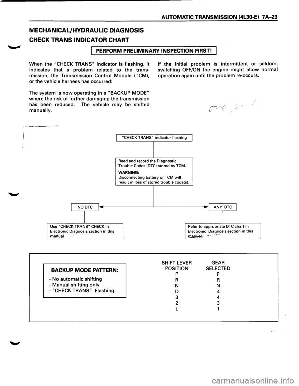
MECHANICAL/HYDRAULIC DIAGNOSIS
CHECK TRANS INDICATOR CHART
AUTOMATIC TRANSMISSION (4L30-E) 7 A-23
I PERFORM PRELIMINARY INSPECTION FIRST!
When the "CHECK TRANS" indicator is flashing, it
indicates that a problem related to the trans
mission, the Transmission Control
Module (TCM),
or the vehicle harness has occurred:
The system is
now operating in a "BACKUP MODE"
where the risk of further damaging the transmission
has been reduced. The vehicle may be shifted
manually.
If the initial problem is intermittent or seldom,
switching OFF/ON the engine might allow normal
operation again until the problem re-occurs.
I "CHECK TRANS" indicator flashing
I NO DTC I
I
Use "CHECK TRANS" CHECK in
Electronic Diagnosis section in this
manual
BACKUP MODE PATTERN:
-No automatic shifting
- Manual shifting only
-"CHECK TRANS" Flashing
Read and record the Diagnostic
Trouble Codes {DTCI stored by TCM.
WARNING: Disconnecting battery or TCM will result in loss of stored trouble code{s).
I ANY DTC J
I
Refer to appropriate DTC chart in
Electronic Diagnosis sectien in this
l'lUl,IUiah~ c " • •• "
SHIFT LEVER GEAR
POSITION p
R
N
D
3
2
L
SELECTED p
R
N
4
4
3
1
Page 896 of 1928
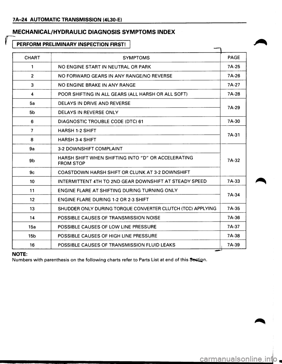
7 A-24 AUTOMATIC TRANSMISSION (4l30-E)
MECHANICAL/HYDRAULIC DIAGNOSIS SYMPTOMS INDEX
rr PERFORM PRELIMINARY INSPECTION FIRST! , -
CHART SYMPTOMS PAGE
1
NO ENGINE START IN NEUTRAL OR PARK 7A-25
2
NO FORWARD GEARS IN ANY RANGE/NO REVERSE 7A-26
3
NO ENGINE BRAKE IN ANY RANGE 7A-27
4
POOR SHIFTING IN ALL GEARS (ALL HARSH OR ALL SOFT) 7A-28
Sa DELAYS IN DRIVE AND REVERSE 7A-29
5b DELAYS
IN REVERSE ONLY
6 DIAGNOSTIC TROUBLE CODE (DTC) 61 7A-30
7 HARSH 1-2
SHIFT 7A-31
8 HARSH 3-4
SHIFT
9a 3-2 DOWNSHIFT
COMPLAINT
9b HARSH SHIFT WHEN SHIFTING INTO "D" OR ACCELERATING 7A-32 FROM STOP
9c COASTDOWN HARSH SHIFT OR CLUNK AT 3-2 DOWNSHIFT
10 INTERMITTENT 4TH TO 2ND GEAR DOWNSHIFT AT STEADY SPEED 7A-33
11 ENGINE FLARE AT SHIFTING
DURING TURNING ONLY 7A-34
12 ENGINE FLARE DURING 1-2 OR 2-3 SHIFT
13 SHUDDER ONLY DURING TORQUE CONVERTER CLUTCH (TCC) APPLYING 7A-35
14
POSSIBLE CAUSES OF TRANSMISSION NOISE 7A-36
15a
POSSIBLE CAUSES OF LOW LINE PRESSURE 7A-37
15b
POSSIBLE CAUSES OF HIGH LINE PRESSURE 7A-38
16
POSSIBLE CAUSES OF TRANSMISSION FLUID LEAKS It 7A-39
= -NOTE:
Numbers with parenthesis on the following charts refer to Parts List at end of this ~n.
•
Page 897 of 1928
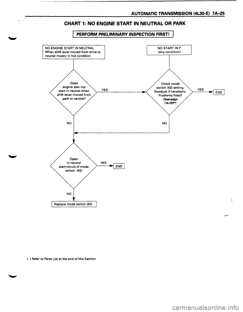
AUTOMATIC TRANSMISSION (4L30-E) 7 A-25
CHART 1: NO ENGINE START IN NEUTRAL OR PARK
PERFORM PRELIMINARY INSPECTION FIRST!
NO ENGINE START IN NEUTRAL
When shift lever moved from drive to neutral mostly in hot condition
Does
engine
also not start in neutral when
shift lever moved from
park to neutral?
NO
Open
in neutral
start circuit of mode
switch (63)
Replace mode switch (63)
( ) Refer
to Parts List at the end of this Section.
YES
NO START IN P
(Any condition)
Check mode
switch
(63) setting.
Readjust
if necessary. Problems fixed?
(~e 7 A-'Hi'1':')
NO
YES ~ ~----l~~
Page 899 of 1928
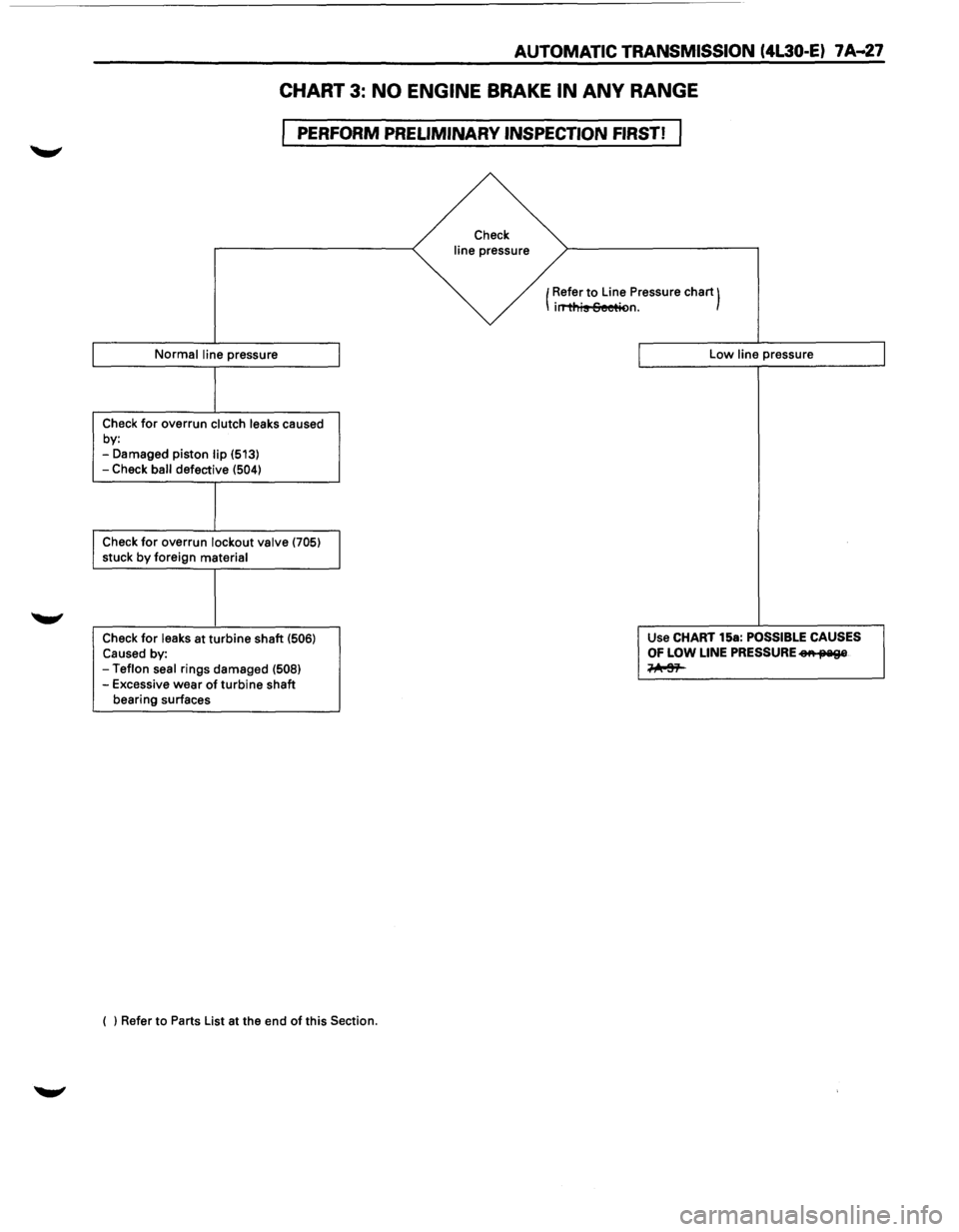
AUTOMATIC TRANSMISSION (4l30-E) 7 A--27
CHART 3: NO ENGINE BRAKE IN ANY RANGE
PERFORM PRELIMINARY INSPECTION FIRST!
Normal line pressure
Check for overrun clutch leaks caused
by:
-Damaged piston lip (513)
-Check ball defective (504)
Check for overrun lockout valve (705) stuck by foreign material
Check
for leaks at turbine shaft (506) Caused by: -Teflon seal rings damaged (508) -Excessive wear of turbine shaft
bearing surfaces
( ) Refer to Parts List at the end
of this Section.
Check
line pressure
(Refer
to Line
Pressure chart) irT'ti'lis Seetit>n.
Low line pressure
Use CHART 15a:
POSSIBLE CAUSES
OF LOW LINE PRESSURE eA fJ'Iil9&
~
Page 901 of 1928
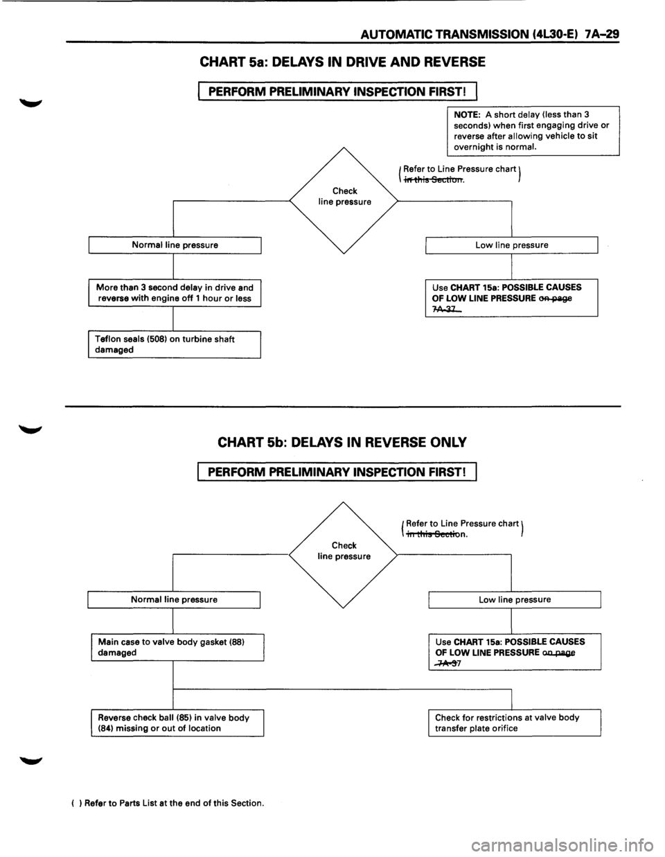
AUTOMATIC TRANSMISSION (4L30·E) 7 A-29
CHART 5a: DELAYS IN DRIVE AND REVERSE
PERFORM PRELIMINARY INSPECTION FIRST! I
Normal line pressure
More than 3 second delay in drive and
reverse with engine off 1 hour or less
Teflon seals (508) on turbine shaft damaged
Check
line pressure
NOTE: A short delay (less than 3
seconds) when first engaging drive or
reverse after allowing vehicle to sit overnight is normal.
1 Refer to Line Pressure chart) I il'fti'1is Section.
Low line pressure
Use CHART 15a:
POSSIBLE CAUSES
OF
LOW LINE PRESSURE OR-page 1-A,.31_
CHART 5b: DELAYS IN REVERSE ONLY
PERFORM PRELIMINARY INSPECTION FIRST!
Normal line pressure
Main case to valve body gasket (88) damaged
Reverse check ball (85) in valve body (84) missing or out of location
( ) Refer to Parts List at the end of this Section.
Check
line pressure (
Refer
to Line
Pressure chart) iii this Section.
Low line pressure
Use CHART 15a:
POSSIBLE CAUSES OF LOW LINE PRESSURE aa..page
~7
Check for restrictions at valve body transfer plate orifice