engine ISUZU TROOPER 1995 Workshop Manual
[x] Cancel search | Manufacturer: ISUZU, Model Year: 1995, Model line: TROOPER, Model: ISUZU TROOPER 1995Pages: 1928
Page 902 of 1928
7 A-30 AUTOMATIC TRANSMISSION (4L30-E)
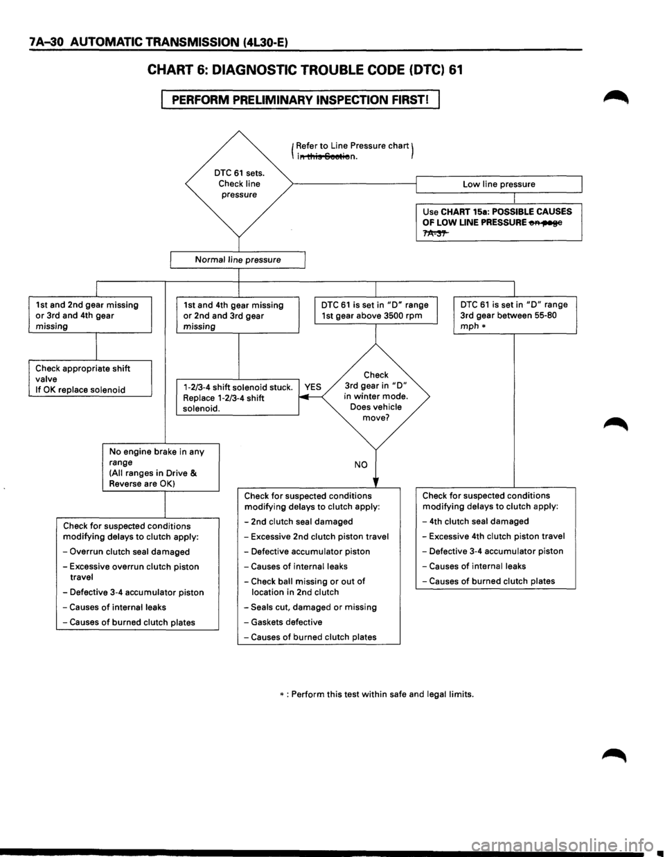
CHART 6: DIAGNOSTIC TROUBLE CODE (DTC) 61
PERFORM PRELIMINARY INSPECTION FIRST!
I
I
DTC 61 sets.
Check line pressure
Normal line pressure
1 Refer to Line Pressure chart) i" this Seetien.
J
Low line pressure
Use
CHART 15a: POSSIBLE CAUSES
OF LOW LINE PRESSURE~
~
1st and 2nd gear missing or 3rd and 4th gear
missing 1st
and 4th gear missing or 2nd and 3rd gear
missing I
DTC 61 is set in "D" range I 1st gear above 3500 rpm
DTC 61 is set in "D" range
3rd gear between 55-80
mph*
I
Check appropriate shift valve Check
If
OK replace solenoid 1-2/3-4 shift solenoid stuck. YES Replace 1-2/3-4 shift 3rd
gear in
"D" in winter mode.
solenoid.
No engine brake in any
range
(All ranges in Drive &
Reverse are OK)
Check for suspected conditions modifying delays to clutch apply:
-Overrun clutch seal damaged
-Excessive overrun clutch piston travel
-Defective 3-4 accumulator piston
-Causes of internal leaks
-Causes of burned clutch plates
Does vehicle move?
NO
' Check for suspected conditions modifying delays to clutch apply:
-2nd clutch seal damaged
-Excessive 2nd clutch piston travel
-Defective accumulator piston
-Causes of internal leaks
-Check ball missing or out of
location in 2nd clutch
-Seals cut, damaged or missing
- Gaskets defective
-Causes of burned clutch plates Check
for suspected
conditions modifying delays to clutch apply:
-4th clutch seal damaged
-Excessive 4th clutch piston travel
-Defective 3-4 accumulator piston
-Causes of internal leaks
-Causes of burned clutch plates
* : Perform this test within safe and legal limits.
..
Page 906 of 1928
7 A-34 AUTOMATIC TRANSMISSION (4L30-E)
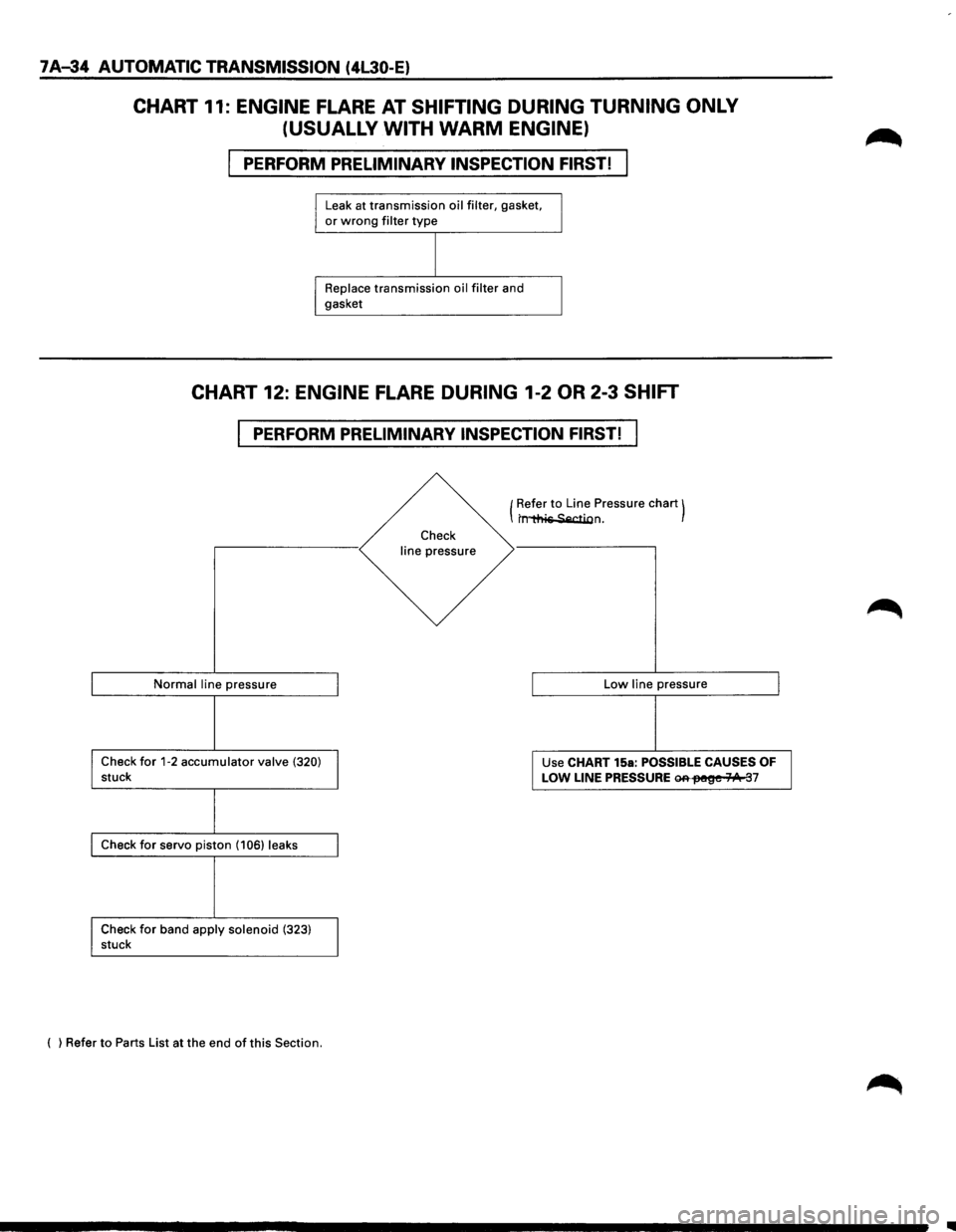
CHART 11: ENGINE FLARE AT SHIFTING DURING TURNING ONLY
(USUALLY WITH
WARM ENGINE)
PERFORM PRELIMINARY INSPECTION FIRST!
Leak at transmission oil filter, gasket, or wrong filter type
Replace transmission oil filter and
gasket
CHART 12: ENGINE FLARE DURING 1-2 OR 2-3 SHIFT
PERFORM PRELIMINARY INSPECTION FIRST!
Normal line pressure
Check for 1-2 accumulator valve (320) stuck
Check for servo piston (106) leaks
Check
for band apply solenoid (323) stuck
( ) Refer
to Parts List at the end of this Section.
Check
line pressure (
Refer
to Line
Pressure chart) t~n.
Low line pressure
Use CHART 15a:
POSSIBLE CAUSES OF
LOW LINE PRESSURE ~fM!~e 71/1t 37
..
Page 911 of 1928
AUTOMATIC TRANSMISSION (4L30-E) 7 A-39
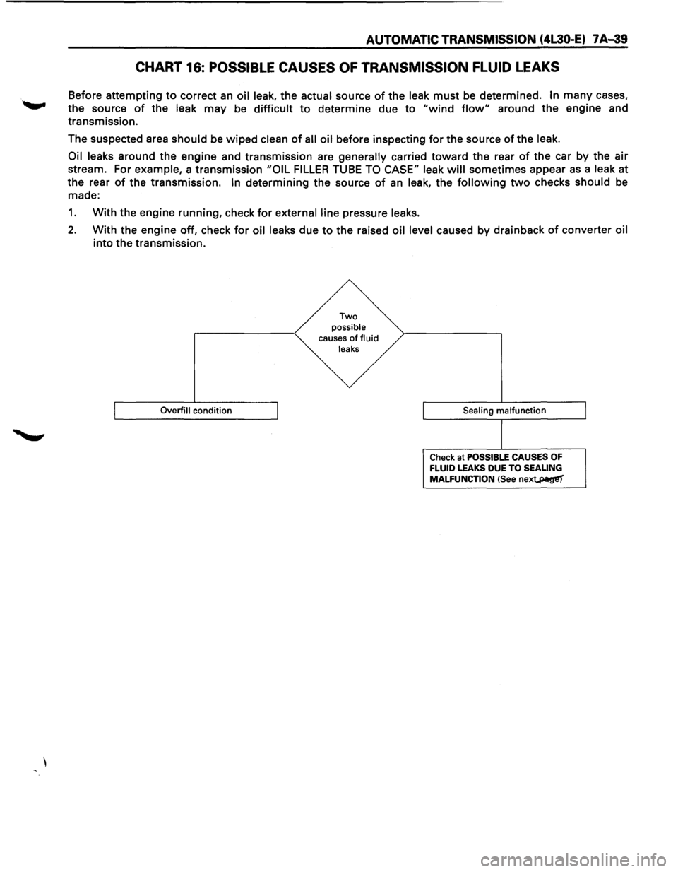
CHART 16: POSSIBLE CAUSES OF TRANSMISSION FLUID LEAKS
Before attempting to correct an oil leak, the actual source of the leak must be determined. In many cases,
the source
of the leak may be difficult to determine due to "wind flow" around the engine and
transmission.
The suspected area
should be wiped clean of all oil before inspecting for the source of the leak.
Oil leaks
around the engine and transmission are generally carried toward the rear of the car by the air
stream. For example, a transmission "OIL FILLER TUBE TO CASE" leak will sometimes appear as a leak at
the rear
of the transmission. In determining the source of an leak, the following two checks should be
made:
1. With the engine running, check for external line pressure leaks.
2. With the engine off, check for oil leaks due to the raised oil level caused by drainback of converter oil
into the transmission.
Overfill condition
Two possible causes of fluid
leaks
Sealing
malfunction
Check at POSSIBLE CAUSES OF FLUID LEAKS DUE TO SEALING
MALFUNCTION (See nex~
Page 913 of 1928
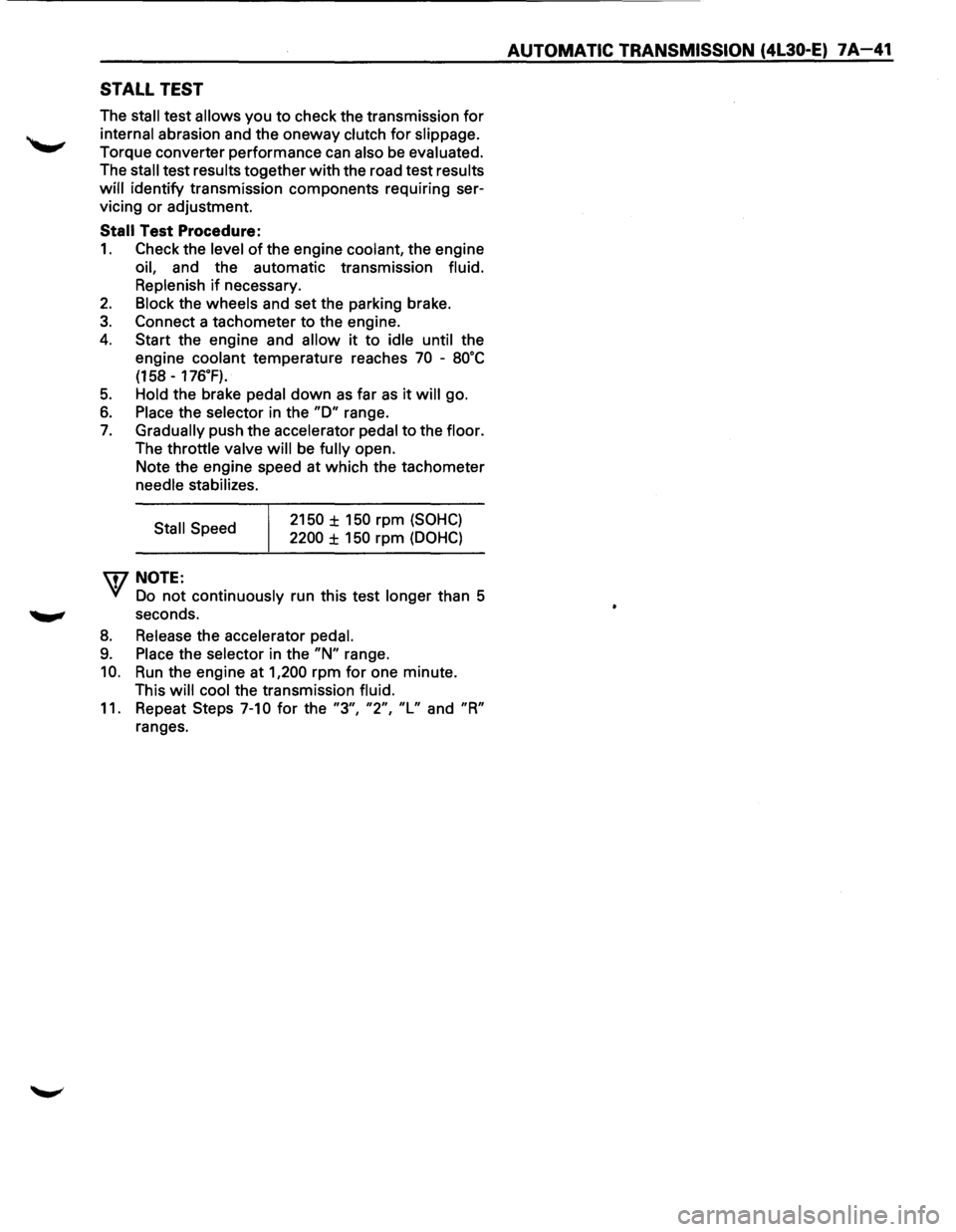
STALL TEST
The stall test allows you to check the transmission for
internal abrasion and the oneway clutch for slippage.
Torque converter performance can also be evaluated.
The
stall test results together with the road test results
will identify transmission components requiring ser
vicing or adjustment.
Stall Test Procedure:
1. Check the level of the engine coolant, the engine
oil, and the automatic transmission fluid.
Replenish
if necessary.
2. Block the wheels and set the parking brake.
3. Connect a tachometer to the engine.
4. Start the engine and allow it to idle until the
engine coolant temperature reaches
70 -8o·c
(158 -176.F).
5. Hold the brake pedal down as far as it will go.
6. Place the selector in the "D" range.
7. Gradually push the accelerator pedal to the floor.
The throttle valve
will be fully open.
Note the engine speed at which the tachometer
needle stabilizes.
Stall Speed
\fl NOTE:
2150 ± 150 rpm (SOHC)
2200 ± 150 rpm (DOHC)
VI Do not continuously run this test longer than 5
........, seconds.
8. Release the accelerator pedal.
9. Place the selector in the "N" range.
10. Run the engine at 1,200 rpm for one minute.
This
will cool the transmission fluid.
11. Repeat Steps 7-10 for the "3", "2", "L" and "R"
ranges.
AUTOMATIC TRANSMISSION (4L30-E) 7A-41
Page 914 of 1928
7 A-42 AUTOMATIC TRANSMISSION (4L30-E)
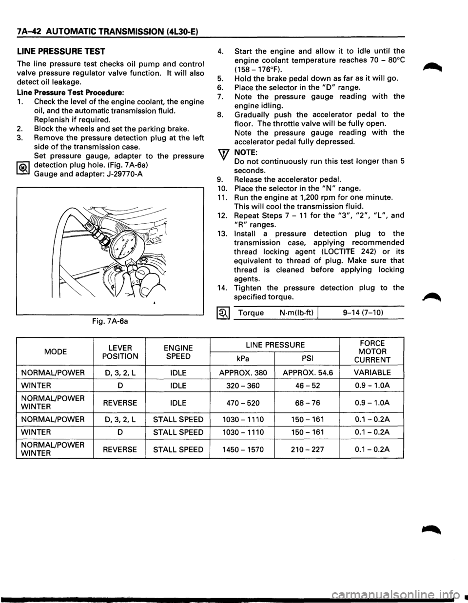
LINE PRESSURE TEST
The line pressure test checks oil pump and control
valve
pressure regulator valve function. It will also
detect oil leakage.
Line Pressure Test Procedure:
1. Check the level of the engine coolant, the engine
oil, and the automatic transmission fluid.
Replenish
if required.
2. Block the wheels and set the parking brake.
3. Remove the pressure detection plug at the left
side of the transmission case.
Set pressure gauge, adapter
to the pressure
l"iC\1 detection plug hole. (Fig. 7 A-6a)
~ Gauge and adapter: J-29770-A
Fig. 7A-6a
LEVER ENGINE
MODE
POSITION
SPEED
NORMAL/POWER D,3,2, L IDLE
WINTER D IDLE
NORMAL/POWER REVERSE IDLE WINTER
NORMAL/POWER
D,3,2,L STALL SPEED
WINTER D STALL SPEED
NORMAL/POWER REVERSE STALL SPEED WINTER
4.
5.
6.
7.
8.
9.
10.
11.
Start the engine and allow it to idle until the
engine
coolant temperature reaches 70 -80°C
(158-176°F).
Hold
the brake pedal down as far as it will go.
Place the selector in the "D" range.
Note the pressure gauge reading
with the
engine
idling.
Gradually
push the accelerator pedal to the
floor. The throttle valve will be fully open.
Note the pressure gauge reading
with the
accelerator
pedal fully depressed.
NOTE:
Do not continuously run this test longer than 5
seconds.
Release the accelerator pedal.
Place
the selector in the "N" range.
Run the engine at
1,200 rpm for one minute.
This
will cool the transmission fluid.
12. Repeat Steps 7-11 for the "3", "2", "L", and
"R" ranges.
13.
Install a pressure detection plug to the
transmission case,
applying recommended
thread
locking agent (LOCTITE 242) or its
equivalent to thread
of plug. Make sure that
thread is cleaned before applying locking
agents.
14. Tighten the pressure detection plug to the
specified torque.
~~~ Torque N·mOb·ft) / 9-14 (7-10)
LINE
PRESSURE FORCE
MOTOR kPa PSI CURRENT
APPROX. 380 APPROX. 54.6 VARIABLE
320-360 46-52 0.9 -1.0A
470-520 68-76 0.9 -1.0A
1030-1110 150-161 0.1-0.2A
1030-1110 150-161 0.1-0.2A
1450-1570 210-227 0.1-0.2A
•
Page 917 of 1928
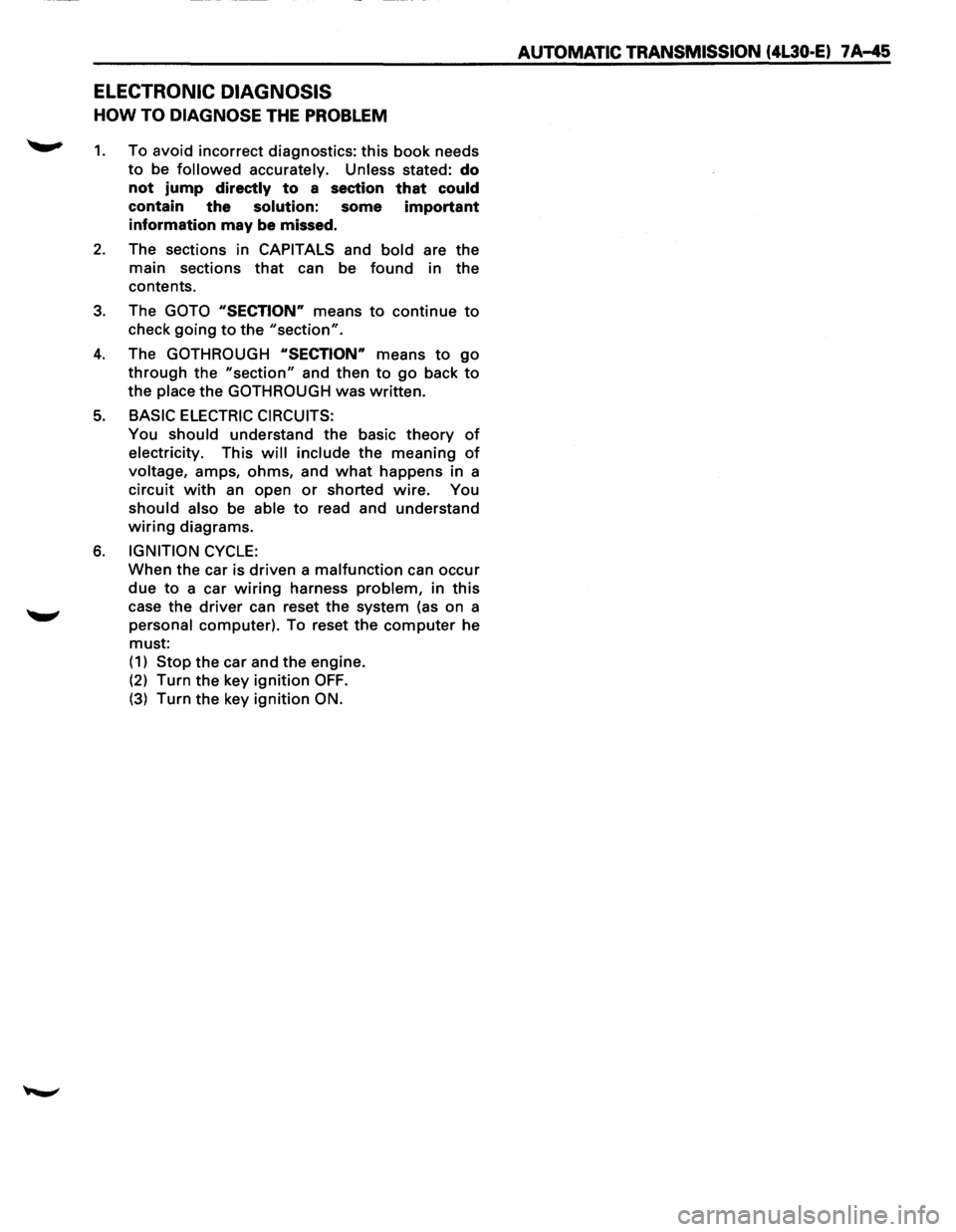
ELECTRONIC DIAGNOSIS
HOW TO DIAGNOSE THE PROBLEM
~ 1. To avoid incorrect diagnostics: this book needs
to be followed accurately. Unless stated: do
not jump
directly to a section that could
contain the solution: some important
information may be missed.
2. The sections in CAPITALS and bold are the
main sections that can be found in the
contents.
3. The GOTO "SECTION" means to continue to
check going to the "section".
4. The GOTHROUGH "SECTION" means to go
through the "section" and then to go back to
the place the GOTHROUGH was written.
5. BASIC ELECTRIC CIRCUITS:
You should understand the basic theory of
electricity. This will include the meaning of
voltage, amps, ohms, and what happens in a
circuit with an open or shorted wire. You
should also be able to read and understand
wiring diagrams.
6. IGNITION CYCLE:
When the car is driven a malfunction can occur
due to a car wiring harness problem, in this
case the driver can reset the system (as on a
personal computer). To reset the computer he
must: (
1) Stop the car and the engine.
(2) Turn the key ignition OFF.
(3) Turn the key ignition ON.
AUTOMATIC TRANSMISSION (4L30·E) 7 A-45
Page 919 of 1928
DIAGNOSTIC CHECK
This test determines if the transmission itself or its
~ inputs or outputs connections or sensors are failing.
IF you have a scan tool TECH1:
NO: Use the CHECK TRANS Indicator diagnostic
codes
GOTO FLASHING CODES.
YES:
1. Connect the TECH1: GOTHROUGH TECH1
CONNECTION.
2. Turn on the ignition but not the engine.
3. Push "F2" on TECH1 to see the Diagnostic
Trouble Code (OTC):
4. IF you have DTC?
YES: write down all code numbers and do the
DTCCHECK
NO: the DTC can not help you finding the
problem.
(1) GOTHROUGH "CHECK TRANS" CHECK
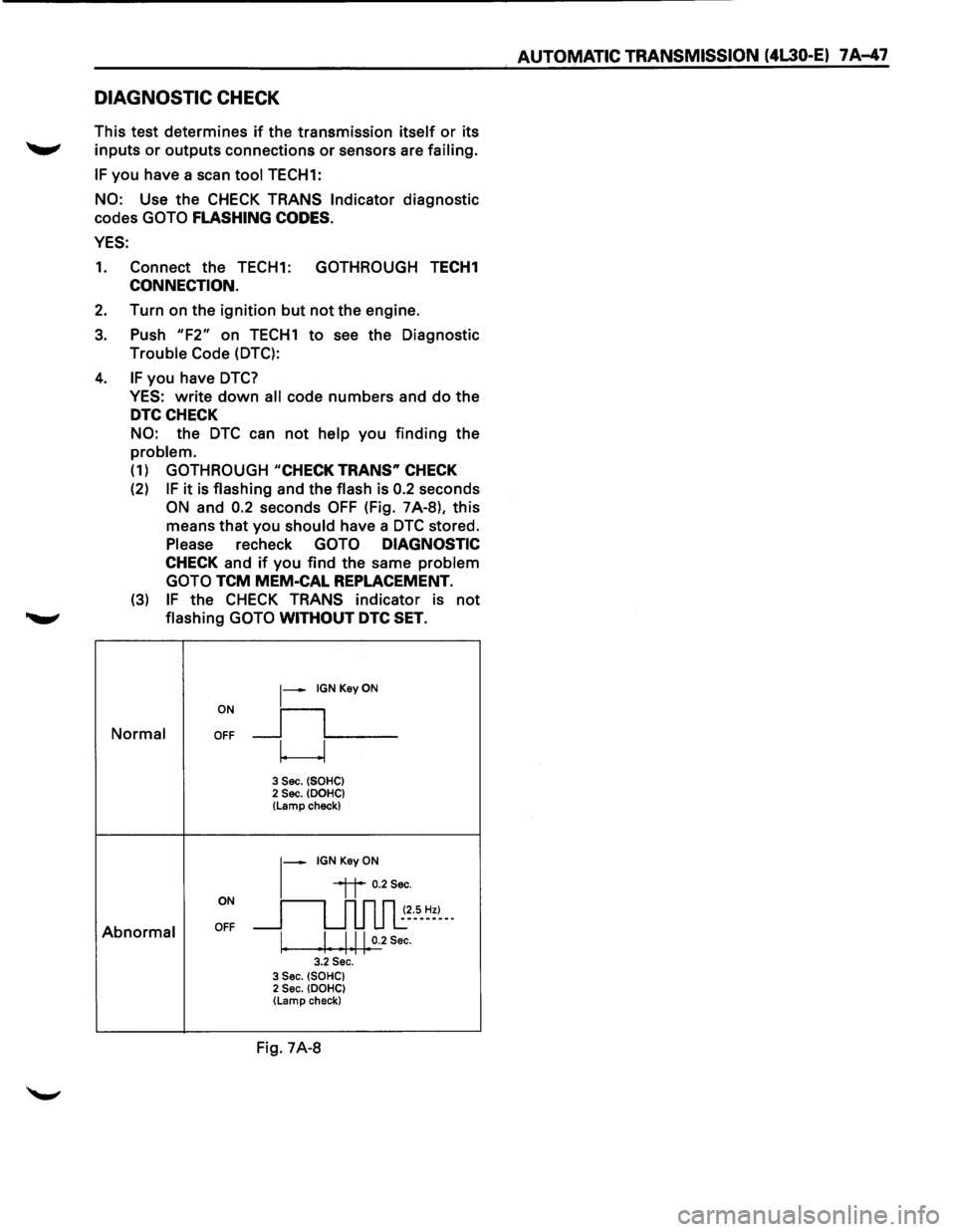
(2) IF it is flashing and the flash is 0.2 seconds
ON and 0.2 seconds OFF (Fig. 7A-8), this
means that you
should have a DTC stored.
Please recheck GOTO DIAGNOSTIC
CHECK and if you find the same problem
GOTO
TCM MEM-CAL REPLACEMENT.
(3) IF the CHECK TRANS indicator is not
........,. flashing GOTO WITHOUT DTC SET.
ON
~-IGNKeyON
__fL__ Normal OFF
w
3 Sec. (SOHC) 2 Sec. (DOHC} (Lamp check)
~-IGNKeyON
ON
~~ 0.2Sec.
~~~5-~=~--
Abnormal OFF
I. I Ill 0.2 Sec. I I I I I 3.2 Sec. 3 Sec. (SOHC) 2 Sec. (DOHC) (Lamp check}
Fig. 7A-8
AUTOMATIC TRANSMISSION (4L30-E) 7 A-47
Page 920 of 1928
7 A-48 AUTOMATIC TRANSMISSION (4L30-E)
"CHECK TRANS" CHECK
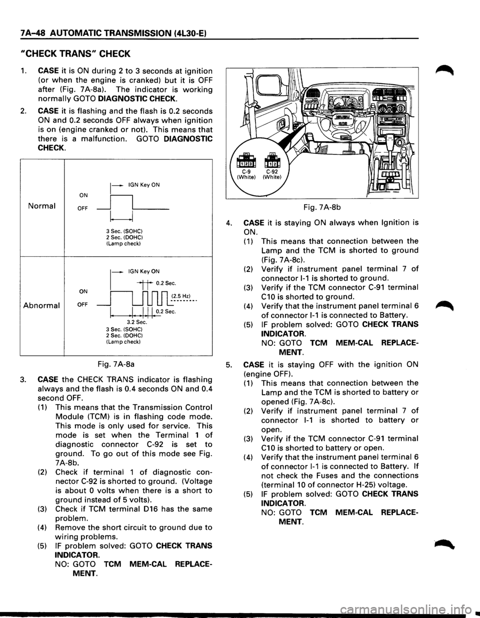
1. CASE it is ON during 2 to 3 seconds at ignition
(or when the engine is cranked) but it is OFF
after (Fig. 7A-8a). The indicator is working
normally GOTO DIAGNOSTIC CHECK.
2. CASE it is flashing and the flash is 0.2 seconds
ON and 0.2 seconds OFF always when ignition
is on (engine cranked or not). This means that
there is a malfunction. GOTO DIAGNOSTIC
CHECK.
Normal
Abnormal
~-IGN Key ON
ON
II
OFF __j l___
~
3 Sec. (SOHC) 2 Sec. (OOHC) (Lamp check)
1-
IGN Key ON
il 0.2Sec.
oN 11 n n n ~~--s_ ~~)-_. OFF __j u u u l:
I. .I. .1.11. 0.2
Sec.
3.2 Sec. 3 Sec. (SOHC) 2 Sec. (OOHC) (Lamp check)
Fig. 7A-8b
4. CASE it is staying ON always when Ignition is
ON.
(1) This means that connection between the
Lamp and the TCM is shorted to ground
(Fig. 7 A-8c).
(2) Verify if instrument panel terminal 7 of
connector 1-1 is shorted to ground.
(3) Verify if the TCM connector C-91 terminal
C10 is shorted to ground.
(4) Verify that the instrument panel terminal 6
of connector 1-1 is connected to Battery.
(5) IF problem solved: GOTO CHECK TRANS
INDICATOR.
NO: GOTO TCM MEM-CAL REPLACE
MENT.
Fig. 7A-8a 5. CASE it is staying OFF with the ignition ON
(engine OFF). 3. CASE the CHECK TRANS indicator is flashing
always and the flash is 0.4 seconds ON and 0.4
second OFF.
(1) This means that the Transmission Control
Module (TCM) is in flashing code mode.
This mode is only used for service. This
mode is set when the Terminal 1 of
diagnostic connector C-92 is set to
ground. To go out of this mode see Fig.
7A-8b.
(2) Check
if terminal 1 of diagnostic con
nector C-92 is shorted to ground. (Voltage
is
about 0 volts when there is a short to
ground instead of 5 volts).
(3) Check if TCM terminal 016 has the same
problem.
(4) Remove the short circuit to ground due to
wiring problems.
(5) IF problem solved: GOTO CHECK TRANS
INDICATOR.
NO: GOTO TCM MEM-CAL REPLACE
MENT.
(1) This means that connection between the
Lamp and the TCM is shorted to battery or
opened (Fig. 7 A-8c).
(2) Verify if instrument panel terminal 7 of
connector 1-1 is shorted to battery or
open.
(3)
Verify if the TCM connector C-91 terminal
C1 0 is shorted to battery or open.
(4)
Verify that the instrument panel terminal 6
of connector 1-1 is connected to Battery. If
not check the Fuses and the connections
(terminal 10 of connector H-25) voltage.
(5) IF problem solved: GOTO CHECK TRANS
INDICATOR.
NO: GOTO TCM MEM-CAL REPLACE
MENT.
Page 924 of 1928
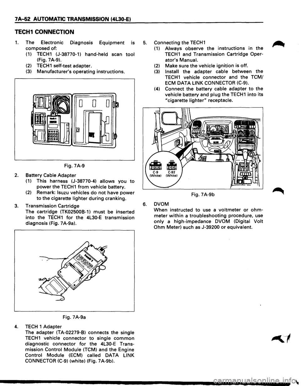
7A..J52 AUTOMATIC TRANSMISSION (4l30-E)
TECH1 CONNECTION
1. The Electronic Diagnosis Equipment is
composed of:
(1) TECH1 (J-38770-1)
hand-held scan tool
(Fig. 7 A-9).
(2)
TECH1 self-test adapter.
(3) Manufacturer's operating instructions.
Fig. 7A-9
2. Battery Cable Adapter
(1) This harness (J-38770-4) allows you to
power the TECH1 from vehicle battery.
(2) Remark:
lsuzu vehicles do not have power
to the cigarette lighter during cranking.
3. Transmission Cartridge
The cartridge
(TK025008-1) must be inserted
into the TECH1 for the 4L30-E transmission
diagnosis (Fig. 7 A-9a).
Fig. 7A-9a
4. TECH 1 Adapter
The adapter
(TA-02279-B) connects the single
TECH1 vehicle connector to single common
diagnostic connector for the 4L30-E Trans
mission
Control Module (TCM) and the Engine
Control Module (ECM) called DATA LINK
CONNECTOR (C-9)
(white) (Fig. 7A-9b).
5. Connecting the TECH1 ~
(1) Always observe the instructions in the
TECH1 and Transmission Cartridge Oper-
ator's
Manual.
(2) Make sure the vehicle ignition is off.
(3) Install the adapter cable between the
TECH1 vehicle connector and the TCM/
ECM
DATA LINK CONNECTOR (C-9).
(4) Connect the battery cable adapter to the
vehicle battery and plug the TECH1 into its
"cigarette lighter" receptacle.
Fig. 7A-9b
6. DVOM
When instructed to use a voltmeter or ohm
meter within a troubleshooting procedure, use
only a high-impedance DVOM (Digital Volt
Ohm
Meter) such as J-39200 or equivalent.
Page 925 of 1928
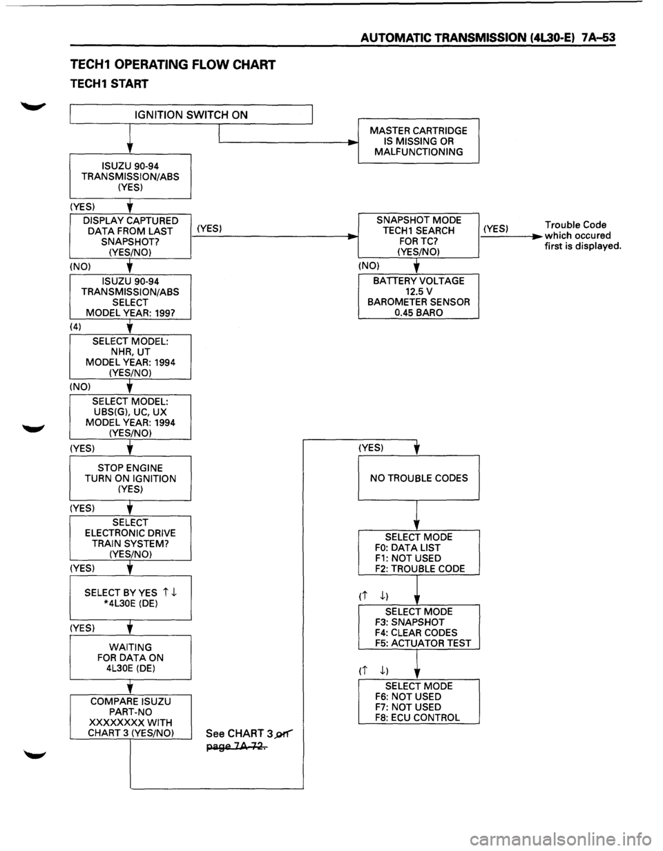
TECH1 OPERATING FLOW CHART
TECH1 START
IGNITION SWITCH ON
ISUZU 90-94
TRANSMISSION/ASS (YES)
(YES)
'
DISPLAY CAPTURED
OAT A FROM LAST (YES) SNAPSHOT?
(YES/NO)
(NO)
'
ISUZU 90-94
TRANSMISSION/ASS SELECT MODEL YEAR: 199?
(4)
'
SELECT MODEL: NHR, UT
MODEL YEAR: 1994 (YES/NO)
(NO)
'
SELECT MODEL: UBS(G), UC, UX
MODEL YEAR: 1994 (YES/NO)
(YES) t
STOP ENGINE TURN ON IGNITION (YES)
(YES)
'
SELECT ELECTRONIC DRIVE
TRAIN SYSTEM? (YES/NO)
(YES)
' SELECT BY YES i ,J.. *4L30E (DE)
(YES)
' WAITING FOR DATA ON 4L30E (DE)
'
COMPARE ISUZU
PART-NO
XXXXXXXX WITH CHART 3 (YES/NO) See CHART 3J)f"'"'"
page 2A +~.
__, -
AUTOMATIC TRANSMISSION (4L30-E) 7 A-53
MASTER CARTRIDGE
IS MISSING OR MALFUNCTIONING
SNAPSHOT MODE
TECH1 SEARCH
FORTC?
(YES/NO)
(NO)
'
BATIERY VOLTAGE 12.5 v BAROMETER SENSOR
0.45 BARO
(YES)
' NO TROUBLE CODES
SELECT MODE FO: OAT A LIST F1: NOT USED F2: TROUBLE CODE
rt ,J..)
SELECT MODE F3: SNAPSHOT F4: CLEAR CODES F5: ACTUATOR TEST
(i ,J..) ,
SELECT MODE F6: NOT USED F7: NOT USED F8: ECU CONTROL
(YES) ...
Trouble Code which occured
first is displayed.