engine ISUZU TROOPER 1995 Workshop Manual
[x] Cancel search | Manufacturer: ISUZU, Model Year: 1995, Model line: TROOPER, Model: ISUZU TROOPER 1995Pages: 1928
Page 868 of 1928
6F-6 ENGINE EXHAUST (V6 3.2L)
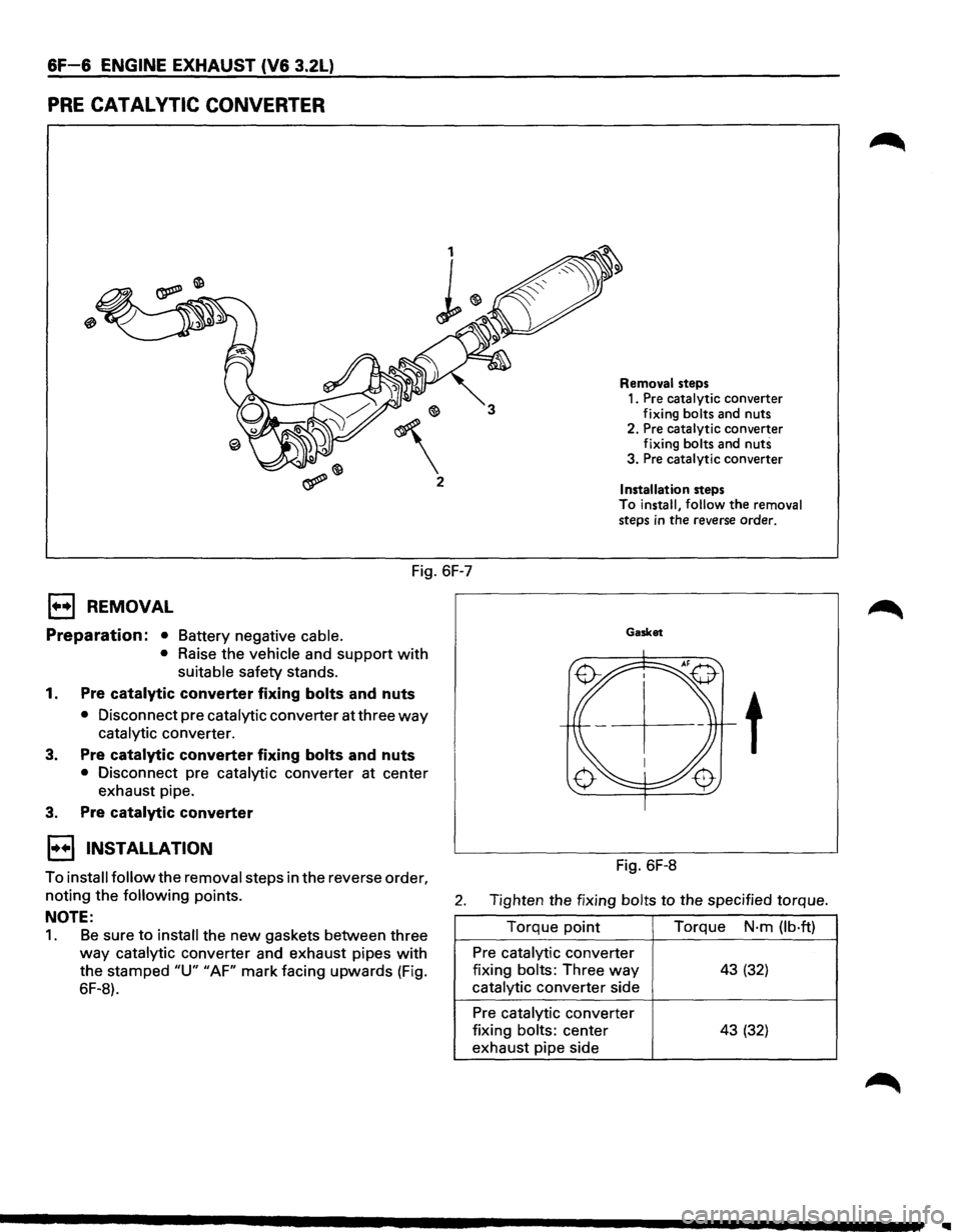
PRE CATAL VTIC CONVERTER
2
Fig. 6F-7
1••1 REMOVAL
Preparation: • Battery negative cable.
•
Raise the vehicle and support with
suitable safety stands.
1. Pre catalytic converter fixing bolts and nuts
• Disconnect pre catalytic converter at three way
catalytic converter.
3. Pre catalytic converter fixing bolts and nuts
• Disconnect pre catalytic converter at center
exhaust pipe.
3. Pre catalytic converter
1••1 INSTALLATION
Removal steps
1. Pre catalytic converter
fixing bolts and nuts
2. Pre catalytic converter
fixing bolts and
nuts 3. Pre catalytic converter
Installation steps To install, follow the removal
steps in the reverse order.
Gasket
t
Fig. 6F-8
To install follow the removal steps in the reverse order,
noting the following points. 2. Tighten the fixing bolts to the specified torque.
NOTE:
1. Be sure to install the new gaskets between three
way catalytic converter and exhaust pipes with
the stamped "U" "AF" mark facing upwards (Fig.
6F-8). Torque
point
Pre catalytic converter
fixing
bolts: Three way
catalytic converter side
Pre catalytic converter
fixing
bolts: center
exhaust pipe side Torque
N·m
(lb·ft)
43 (32)
43 (32)
Page 869 of 1928
EXHAUST SILENCER
4
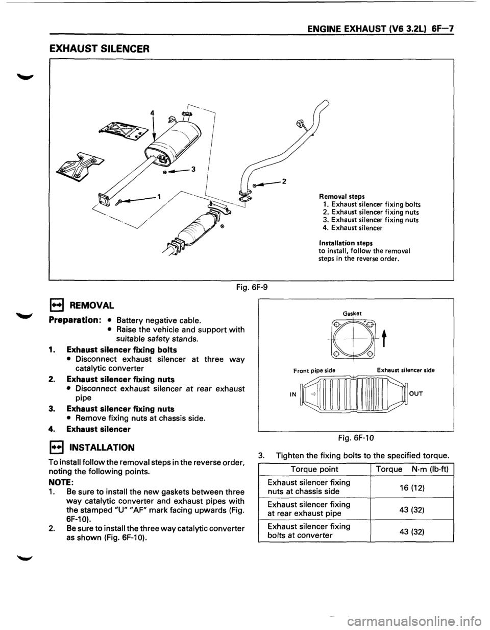
Fig. 6F-9
E) REMOVAL
Preparation: •
Battery negative cable.
• Raise the vehicle and support with
suitable safety stands.
1. Exhaust silencer fixing bolts
• Disconnect exhaust silencer at three way
catalytic converter
2. Exhaust silencer fixing nuts
• Disconnect exhaust silencer at rear exhaust
pipe
3. Exhaust silencer fixing nuts
• Remove fixing nuts at chassis side.
4. Exhaust silencer
ENGINE EXHAUST (V6 3.2L) 6F-7
Removal steps
1. Exhaust silencer fixing bolts 2. Exhaust silencer fixing nuts
3. Exhaust silencer fixing nuts
4. Exhaust silencer
Installation
steps to install, follow the removal steps in the reverse order.
Gasket
Fig. 6F-10
1••1 INSTALLATION
To install follow the removal steps in the reverse order,
noting the following points.
3. Tighten the fixing bolts to the specified torque.
NOTE:
1. Be sure to install the new gaskets between three
way catalytic converter and exhaust pipes with
the stamped "U" "AF" mark facing upwards (Fig.
SF-10).
2. Be sure to install the three way catalytic converter
as shown (Fig. SF-10).
Torque point
Exhaust silencer fixing
nuts at chassis side
Exhaust silencer fixing
at rear exhaust pipe
Exhaust silencer fixing
bolts
at converter Torque
N·m
(lb·ft)
16 (12)
43 (32)
43 (32)
Page 870 of 1928
6F-8 ENGINE EXHAUST (V6 3.2L)
REAR EXHAUST PIPE
2
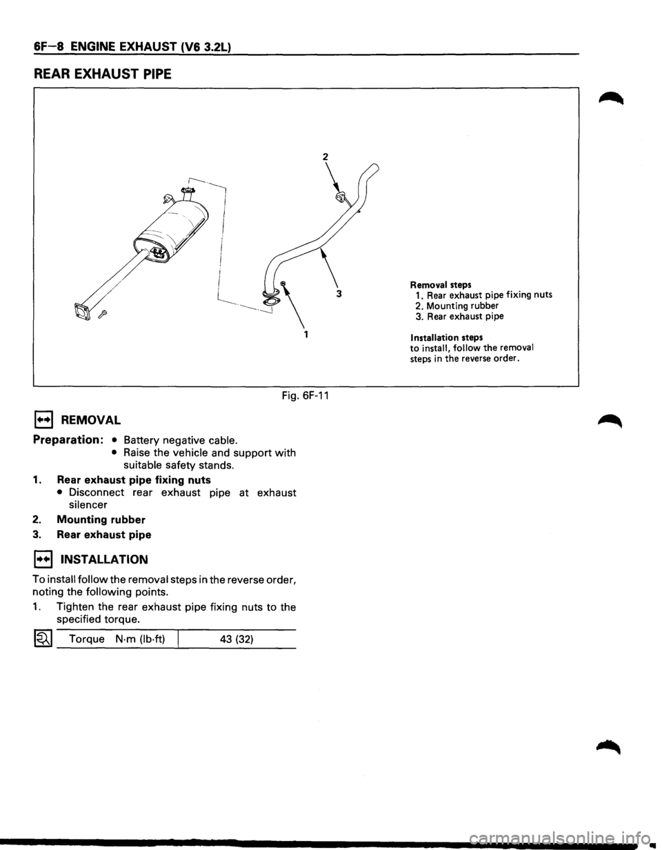
Fig. 6F-11
1+•1 REMOVAL
Preparation: • Battery negative cable.
• Raise the vehicle and support with
suitable safety stands.
1. Rear exhaust pipe fixing nuts
• Disconnect rear exhaust pipe at exhaust
silencer
2. Mounting rubber
3. Rear exhaust pipe
1••1 INSTALLATION
To install follow the removal steps in the reverse order,
noting the
following points.
1. Tighten the rear exhaust pipe fixing nuts to the
specified torque.
1«1 Torque N-m (lb·ft) 43 (32)
Removal steps 1. Rear exhaust pipe fixing nuts
2. Mounting rubber
3. Rear exhaust pipe
Installation steps to install, follow the removal steps in the reverse order.
1111
Page 871 of 1928
MOUNTING RUBBER
ENGINE EXHAUST (V6 3.2L) 6F-9
3
Removal steps 1. Center exhaust pipe mounting
rubber
2. Rear side mounting rubber
of exhaust silencer 3. Rear exhaust pipe mounting
rubber
Installation steps
To install, follow the removal steps in the reverse order.
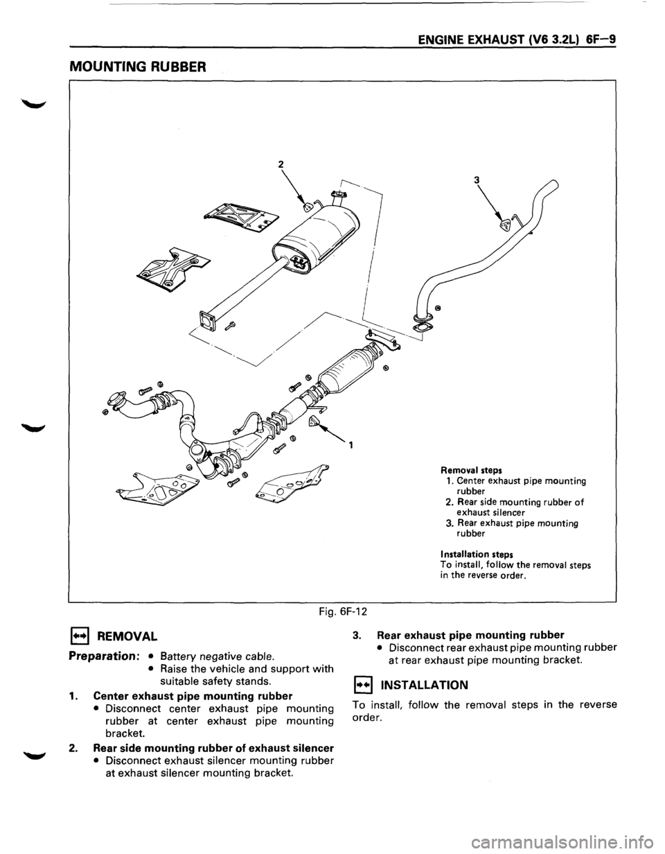
Fig. 6F-12
E) REMOVAL
Preparation: • Battery negative cable.
• Raise the vehicle and support with
suitable safety stands.
1. Center exhaust pipe mounting rubber
• Disconnect center exhaust pipe mounting
rubber at center exhaust pipe mounting
bracket.
2. Rear side mounting rubber of exhaust silencer
• Disconnect exhaust silencer mounting rubber
at exhaust silencer mounting bracket.
3. Rear exhaust pipe mounting rubber
• Disconnect rear exhaust pipe mounting rubber
at rear exhaust pipe mounting bracket.
1••1 INSTALLATION
To install, follow the removal steps in the reverse
order.
Page 872 of 1928
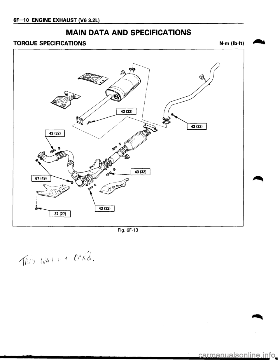
6F-1 0 ENGINE EXHAUST (V6 3.2L)
MAIN DATA AND SPECIFICATIONS
TORQUE SPECIFICATIONS
Fig. 6F-13
N·m (lb·ft) ,-.
..
Page 876 of 1928
•
"'Tl c3' -..J )> I "'
~ )
DASH
BOARD
DISPLA
V
*
*
*
*
ATF
WARNING
LAMP
CHECK
TRANS
LAMP
POWER DRIVE MODE LAMP WINTER DRIVE MODE LAMP
~----------------
SHIFT INDICATOR
LAMP
COMPENSATION
FOR
ENGINE
LOAD
AIR CONDITIONING SWITCH
TI
DRIVER'S
INPUT
liJ
MANUAL
SELECTOR
~
KICK-DOWN SWITCH
" ~
BRAKE
SWITCH
*
(AfT
SHIFT INDICATOR)
CONTROL
UNIT
---
' ---
I-------------,
il
PUSH BUTTON
FOR
NORMALJPOWER
DRIVE MODE
ON-BOARD DIAGNOSTIC
j4
.. ,
..
l__l--1 L_-$-L_g
ENGINE CONTROL
MODULE
(ECM)
_ IGNITION
CONTROL
I
MODULE
i
THROTTLE POSITION
SENSOR
ENGINE SPEED SENSOR
l
I
I -
ENGINE COOLANT TEMPERATU~,_.TCH
)
I +12 IGNITION
• •
TRANSMISSION
CONTROL MODULE
(TCM)
j
L I
BATTERY
)
--
~
'
5SOLENOID VALVES
il
-·----·
___.
u
PUSH BUTTON
FOR
WINTER DRIVE MODE
OTHERS
OVERDRIVE
OFF
SIGNAL
(CRUISE CONTROLLER)
ABS
SIGNAL
(ABS CONTROLLER)
f.-
n_
VEHICLE SPEED
SENSOR
f-
/
ATF TEMPERATURE SENSOR
L__ L__
[PRNDJ2L
I MODE SWITCH
-
m
.....
r-
)>
m
I
(")
..;=...
-t
)>
;::g 0
c:
2
-1
-
0
(")
s:
(")
~
0
-
2
n
-t
-1
;::g
:a
0
)> z
r-
en
c
s:
:;
(i)
C)
en
~
0 z
3:
-..;=... r-w 0 I !!!
)
Page 877 of 1928
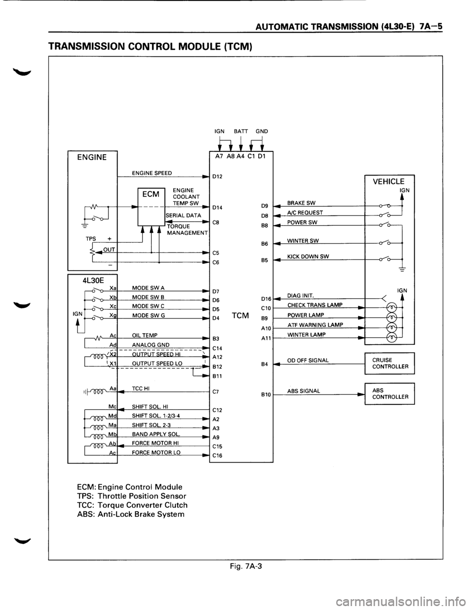
AUTOMATIC TRANSMISSION (4l30-E) 7A-5
TRANSMISSION CONTROL MODULE (TCM)
ENGINE
ENGINE SPEED
ECM ENGINE
COOLANT
TEMPSW
;--J
---
SERIAL DATA
TORQUE
t MANAGEMENT TPS +
.L OUT
I -
4L30E
.J:
X a MODE SWA
Xb MODE SWB
Xc MODE SWC
Xg MODE SWG
A Ac OIL TEMP
Ad ANALOG GND
~~x OUTPUT SPEED HI
1 X1 OUTPUT SPEED LO
II A a TCCHI
Me SHIFT SOL. HI
~Md SHIFT SOL. 1-2/3-4
~Ma SHIFT SOL. 2-3
~Mb BAND APPLY SOL.
~Ab FORCE MOTOR HI
Ac FORCE MOTOR LO
ECM: Engine Control Module
TPS: Throttle Position Sensor
TCC: Torque Converter Clutch
ABS:
Anti-Lock Brake System
-
1
·-c
IGN BATT GND
h+ri A7 AS A4 C1 01
D12 VEHICLE
IGN
BRAKE SW ~ D14 D9 ~
DB AJC REQUEST /o---
CB BB POWER SW
=~
WINTERSW B6
C5 KICK DOWN SW C6 B5
-=
D7 IGN
D16 DIAG INIT. D6
~
D5 C10 CHECK TRANS LAMP
D4 TCM 89 POWER LAMP
A10 ATF WARNING LAMP ~
¥ 83 A11 WINTER LAMP
C14
A12
OD OFF SIGNAL CRUISE 812 84 CONTROLLER
811
C7 ABSSIGNAL ABS
810 CONTROLLER
C12
A2
A3
AS
C15
C16
Fig. 7A-3
Page 878 of 1928
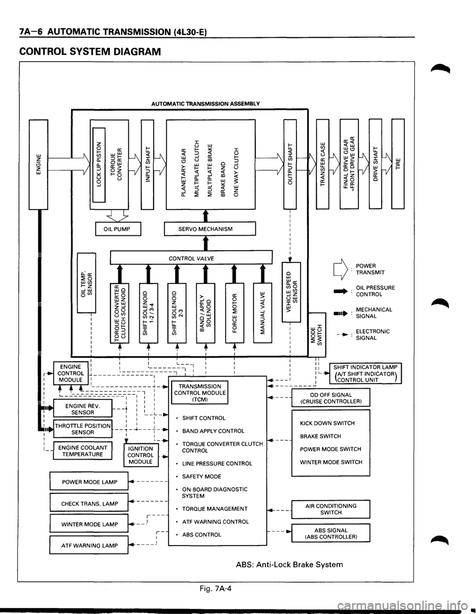
7A-6 AUTOMATIC TRANSMISSION (4L30-E)
CONTROL SYSTEM DIAGRAM
L1J ~ (!) z L1J
I
I
lr
t:··
~ .. I I
I
I
AUTOMATIC TRANSMISSION ASSEMBLY
O.:a: :Eo LLJ(J) t-z --' L1J oVl
ENGINE COOLANT TEMPERATURE
ffio ~---a:O wz >LLJ z--' oo uCJ> w::C :::>u at-a:=> ~d
0 0 z ... w, --'"' o-.. (J)N t-.!-u.. J: CJ)
IGNITION
CONTROL .
MODULE
~==PO=W==ER==M=O=D=E=L=A=M=P~r.-------
r-------CHECK TRANS. LAMP
~=W=IN=T=E=R=M=O=D=E=LA=M=P~~--J---
::c u L1J a: 1-:.:: ::c <( :::> <( u L1J --' a: 1-(!) u al :::> >-L1J L1J 0 --' 1-~ z u a: :5 <( ~ ~ --' al Cl.
Cl. L1J i=
i= L1J ~ z :.:: --' --' <( L1J :5 :::> :::> a: z Cl. ::!: ::!: al 0
0 a: L1J 0 >-0 > --'o --' z (l._ 1-<( L1J Cl.Q 0 > __,...,
SHIFT
CONTROL
BAND APPLY CONTROL
TORQUE CONVERTER CLUTCH CONTROL
LINE PRESSURE CONTROL
SAFETY MODE
ON-BOARD DIAGNOSTIC
SYSTEM
TORQUE MANAGEMENT
ATF WARNING CONTROL
r-ABS CONTROL
L--A-T_F_w_A_R_N_I_N_G_L_A_M_P_...Jr---_l 1---------------'
0 L1J "'a: Bio wVl __,z uw J:Vl L1J >
POWER c): TRANSMIT
.... : OIL PRESSURE
CONTROL
MECHANICAL
...• : SIGNAL
LLJJ: ou ELECTRONIC ot:: -•: ::!:~ SIGNAL
KICK DOWN SWITCH
BRAKE SWITCH
POWER MODE SWITCH
WINTER MODE SWITCH
AIR CONDITIONING
SWITCH
ABS
SIGNAL (ASS CONTROLLER)
ABS: Anti-Lock Brake System
Fig. 7A-4
..
Page 879 of 1928
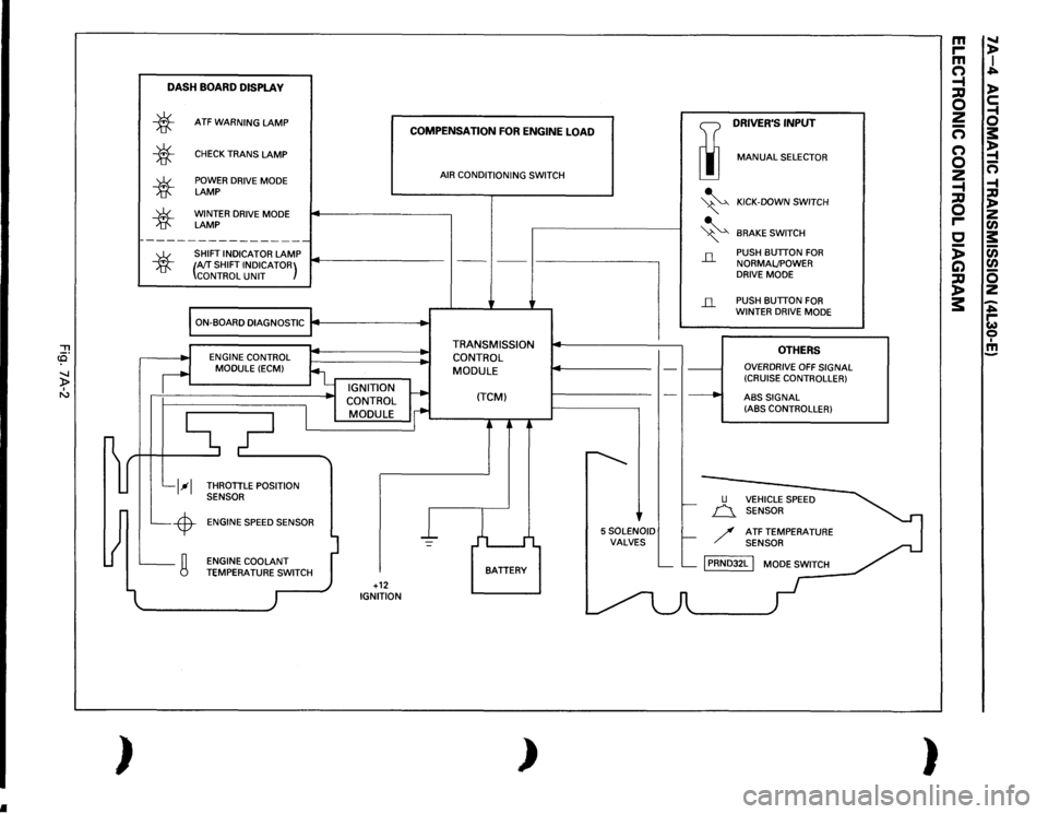
1. SHIFT CONTROL
The transmission gear is shifted according to the
shift pattern selected by the driver.
~ In shifting gears, the gear ratio is controlled by the
ON/ OFF signal using the 1-2/3-4 shift solenoids and
the 2-3 shift solenoid.
2. BAND APPLY CONTROL
The band apply is controlled when in the 3-2
downshift (engine overrun prevention) and the
garage shift (shock control).
The band
apply solenoid is controlled by the signal
from the Pulse Width Modulation (PWM) to regulate
the
flow of the oil.
3. TORQUE CONVERTER CLUTCH CONTROL
The clutch ON/OFF is controlled by moving the
converter clutch valve through shifting Torque
Converter Clutch
(TCC) solenoid using the ON/OFF
signal.
4. LINE PRESSURE CONTROL
The throttle signal allows the current signal to be
sent
to the force motor. After receiving the current
signal, the force motor activates the pressure
regulator valve to regulate the line pressure.
5. ON-BOARD DIAGNOSTIC SYSTEM
Several malfunction displays can be stored in the
Transmission Control Module (TCM) memory, and
read
out of it afterward.
The serial data lines, which are required for the
testing of the final assembly and the coupling to
other electronic modules, can be regulated by this
function.
6 FAIL-SAFE MECHANISM
If there is a problem in the transmission system, the
TCM will go into a "backup" mode. The vehicle can
still be driven, but the driver must use the gear
lever to shift gears.
7. TORQUE MANAGEMENT CONTROL
The TCM sends the absolute spark advance signal
to the Engine Control Module (ECM) while the
transmission is being shifted, to control the engine
spark timing in compliance with the vehicle running
condition to reduce the shocks caused by the
change of speed.
8. ATF WARNING CONTROL
The oil temperature sensor detects the ATF oil
temperature to control the oil temperature warning,
TCC and the winter mode.
9. ABS CONTROL
When the select lever is at "L" or "R" range, a
signal is sent
to the ABS controller as one of the
ABS control conditions.
AUTOMATIC TRANSMISSION (4L30-E) 7A-7
Page 883 of 1928

AUTOMATIC TRANSMISSION (4L30-E) 7 A-11
FUNCTIONS OF INPUT /OUTPUT COMPONENTS
Components Function
Speed sensor
Senses rotation
of output shaft and feeds the data to Transmission
(fixed
to transmission (T/M)) Control Module (TCM)
Throttle Senses the extent of throttle valve opening and the speed of the throttle
position sensor (TPS) valve lever motion to open the valve and feeds the data to TCM (fed to
(fixed to engine)
Engine Control Module (ECM) also)
I
Brake Switch (SW) Senses whether the driver has pressed the brake pedal or not and feeds
N (fixed
to brake pedal) the
information to TCM
p Kick-down SW (fixed to Senses whether the driver has pushed the accelerator pedal fully or not
u accelerator pedal) and feeds the information to TCM
T Mode
SW (fixed to T/M) Senses the select lever position and feeds the information to TCM
s Power drive SW Senses whether the driver has selected the power mode and feeds the
I (fixed to front console) information to TCM
G T/M
oil temp. sensor
Senses the T/M oil temperature and feeds the data to TCM
N Engine
coolant Senses the engine cooling water temperature and feeds the data to TCM
A temperature
SW (feeds the signal from ECM)
L
Engine speed
signal Feeds the signals monitoring engine speed to TCM from Ignition Control
Module
(fed to ECM also)
Air conditioning Senses whether the air conditioner has been switched on or not and
information feeds the information
to TCM
On-board diagnostic
input By monitoring the Ground (GND), the location of failure is shown on the
T/M
monitor lamp ("CHECK TRANS") by flashing the diagnostic trouble
code
Winter switch
Senses whether the driver has selected the winter mode, and feeds the
(fixed
to front console) information to TCM
Cruise
controller Downshift takes place when Overdrive OFF signal is received from auto
(Overdrive
OFF signal) cruise control unit
Shift
solenoid Selects shift point and gear position suited to the vehicle running con-s 1-2/3-4, 2-3
dition on the basis of TCM output 0 Band apply solenoid
Controls oil flow suited to the vehicle running condition on the basis of L
E TCM output
0 N
Torque
Converter Controls clutch engagement/disengagement suited to the vehicle
u 0 Clutch solenoid running condition on the basis of TCM output
T I Force motor Adjusts the oil pump delivery pressure to line pressure suited to the p D
(Pressure regulator vehicle running condition on the basis of TCM output u valve) T
Power drive mode lamp
Informs the driver whether the vehicle is in power mode or not
s Winter drive mode lamp Informs the driver whether the vehicle is in winter mode or not
I T/M monitor lamp Informs the driver of failure in the system. It also displays the self diagnosis
G
("CHECK TRANS") code.
N Data Link Connector
(DLC) When connected with TECH 1 or tester, can communicate the data for A
L function
check, etc. (fed to ECM also). When TECH 1 is not connected, can
communicate the
signal for torque management with ECM.
Self-diagnosis connector
When short-circuited with the bipolar connector, the T/M monitor lamp
displays
a failure by code.
ATF warning
lamp Lights when ATF oil temperature rises.
ABS signal When the select lever is at "Reverse" or "L" range, sends a signal to the
ABS controller as one of the ABS control conditions.