air condition ISUZU TROOPER 1995 Owner's Guide
[x] Cancel search | Manufacturer: ISUZU, Model Year: 1995, Model line: TROOPER, Model: ISUZU TROOPER 1995Pages: 1928
Page 68 of 1928
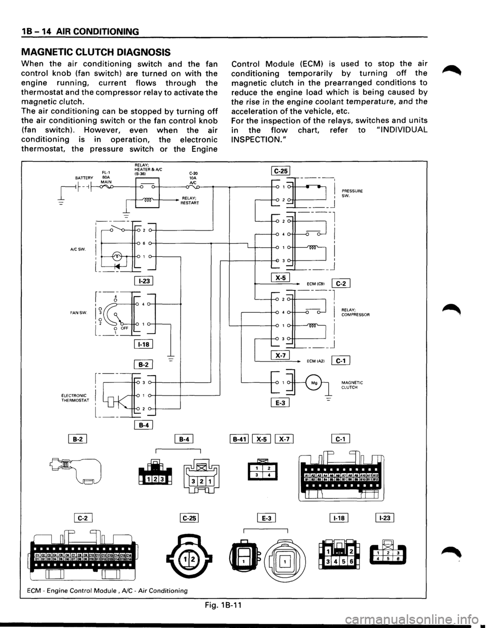
18-14 AIR CONDITIONING
MAGNETIC CLUTCH DIAGNOSIS
When the air conditioning switch and the fan
control knob (fan switch) are turned on with the
engine running, current flows through the
thermostat and the compressor relay to activate the
magnetic clutch.
The air conditioning can be stopped by turning off
the air conditioning switch or the fan control knob
(fan switch). However, even when the air
conditioning is in operation, the electronic
thermostat, the pressure switch or the Engine
BATTER y
~
A/C SW.
FAN SW.
FL-1 BOA MAIN -.Y""'
I
RELAY; HEATER&A/C (8-36)
-
·~
~-----;::: -
I ,--<> -v--ro 2
I 6
! -&r ro 1 l ~ .... --~-'---
11-231
r-g-I 4
I~ 0 I 2 1
l __ 9_ OFF -
lli!J
~
r-----3 I
I 1
I 2 -
ELECTRONIC ~ THERMOSTAT
l __ _
C-20 10A Jd.C
RELAY; RESTART
-=-
ECM -Engine Control Module , NC -Air Conditioning
Control Module (ECM) is used to stop the air
conditioning temporarily by turning off the
magnetic clutch in the prearranged conditions to
reduce the engine load which is being caused by
the rise in the engine coolant temperature, and the
acceleration of the vehicle, etc.
For
the inspection of the relays, switches and units
in the flow chart, refer to "INDIVIDUAL
INSPECTION."
,....-1
2 ......_
.....-=.-2
40. r-
1v-
3
......._ =--
~
I ___ j
PRESSURE
SW.
ECMIC91
~
---2 ----l
•o--
1v-
3
-~-@]
~1
L
[ill
I
I RELAY; COMPRESSOR
I
I I ___ j
ECMIA21 ~
:=:>
MAGNETIC
CLUTCH
,.----I In_ r-r
A1 Kl ., .. ...... A& .. A7 AI ld A10 A11A12 .... •• ., .. a1o an 112
'It!
~
~
Fig.1B-11
Page 69 of 1928
AIR CONDITIONING 1 B -15
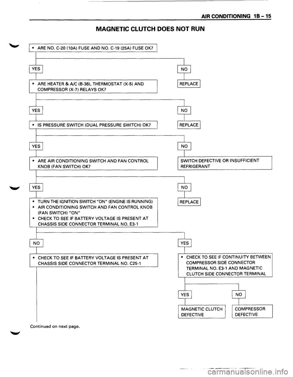
MAGNETIC CLUTCH DOES NOT RUN
• ARE NO. C-20 (10A) FUSE AND NO. C-19 (25A) FUSE OK?
•
ARE HEATER & A!C (B-36), THERMOSTAT (X-5) AND
COMPRESSOR (X-7) RELAYS OK?
•
ARE AIR CONDITIONING SWITCH AND FAN CONTROL
KNOB
(FAN SWITCH) OK?
•
TURN THE IGNITION SWITCH "ON" (ENGINE IS RUNNING)
• AIR CONDITIONING SWITCH
AND FAN CONTROL KNOB
(FAN SWITCH) "ON"
• CHECK TO SEE IF BATTERY VOLTAGE IS PRESENT AT
CHASSIS SIDE CONNECTOR TERMINAL NO. E3-1
• CHECK TO SEE IF BATTERY VOLTAGE IS PRESENT AT
CHASSIS SIDE CONNECTOR TERMINAL NO. C25-1
Continued on next page.
SWITCH DEFECTIVE OR INSUFFICIENT
REFRIGERANT
• CHECK TO
SEE IF CONTINUITY BETWEEN
COMPRESSOR SIDE CONNECTOR
TERMINAL NO.
E3-1 AND MAGNETIC
CLUTCH SIDE CONNECTOR TERMINAL
Page 70 of 1928
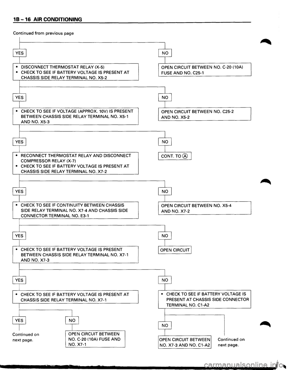
1 B -16 AIR CONDITIONING
Continued from previous page
• DISCONNECT THERMOSTAT RELAY (X-5)
• CHECK TO SEE IF BATTERY VOLTAGE IS PRESENT AT
CHASSIS SIDE RELAY TERMINAL NO. X5-2
• CHECK TO SEE IF VOLTAGE (APPROX. 10V) IS PRESENT
BETWEEN CHASSIS SIDE RELAY TERMINAL NO. X5-1
AND NO. X5-3
• RECONNECT THERMOSTAT RELAY AND DISCONNECT
COMPRESSOR
RELAY (X-7)
• CHECK TO SEE IF BATTERY VOLTAGE IS PRESENT AT
CHASSIS SIDE RELAY TERMINAL NO. X7-2
• CHECK TO SEE IF CONTINUITY BETWEEN CHASSIS
SIDE
RELAY TERMINAL NO. X7-4 AND CHASSIS SIDE
CONNECTOR TERMINAL NO. E3-1
• CHECK TO SEE IF BATTERY VOLTAGE IS PRESENT
BETWEEN CHASSIS SIDE RELAY TERMINAL NO. X7-1
AND NO. X7-3
• CHECK TO SEE IF BATTERY VOLTAGE IS PRESENT AT
CHASSIS SIDE RELAY TERMINAL NO. X7-1
Continued on
next page. OPEN
CIRCUIT BETWEEN
NO. C-20 (10A)
FUSE AND
NO. X7-1 OPEN
CIRCUIT BETWEEN
NO. C-20 (10A)
FUSE AND NO. C25-1
AND NO. X5-2
AND NO. X7-2
• CHECK TO SEE IF BATTERY VOLTAGE IS
PRESENT AT CHASSIS SIDE CONNECTOR
TERMINAL NO. C1-A2
Continued on
NO. X7-3 AND NO. C1-A2 next page.
Page 71 of 1928
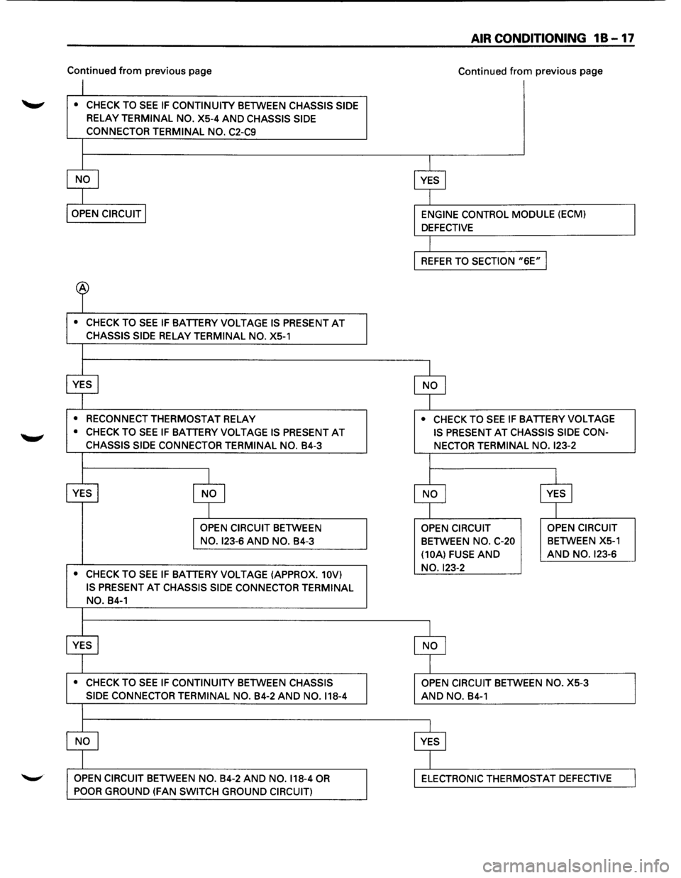
Continued from previous page
~ • CHECK TO SEE IF CONTINUITY BETWEEN CHASSIS SIDE
RELAY TERMINAL NO. X5-4 AND CHASSIS SIDE
CONNECTOR
TERMINAL NO. C2-C9
• CHECK TO SEE IF BATTERY VOLTAGE IS PRESENT AT
CHASSIS SIDE RELAY TERMINAL NO. XS-1
•
RECONNECT THERMOSTAT RELAY
• CHECK TO SEE IF BATTERY VOLTAGE IS PRESENT AT
CHASSIS SIDE CONNECTOR TERMINAL NO. B4-3
OPEN CIRCUIT BETWEEN
NO. 123-6 AND NO. B4-3
• CHECK TO SEE IF BATTERY VOLTAGE (APPROX. 10V)
IS PRESENT
AT CHASSIS SIDE CONNECTOR TERMINAL
NO. B4-1
• CHECK TO SEE IF CONTINUITY BETWEEN CHASSIS
SIDE CONNECTOR
TERMINAL NO. B4-2 AND NO. 118-4
OPEN CIRCUIT BETWEEN NO. B4-2 AND NO. 118-4 OR
POOR GROUND (FAN SWITCH GROUND CIRCUIT)
AIR CONDITIONING 18-17
Continued from previous page
• CHECK TO SEE IF BATTERY VOLTAGE
IS PRESENT
AT CHASSIS SIDE CON
NECTOR TERMINAL NO.
123-2
OPEN CIRCUIT
BETWEEN NO. C-20
(10A) FUSE
AND
NO. 123-2
AND NO. B4-1
OPEN CIRCUIT
BETWEEN XS-1
AND NO. 123-6
ELECTRONIC THERMOSTAT DEFECTIVE
Page 72 of 1928
18-18 AIR CONDITIONING
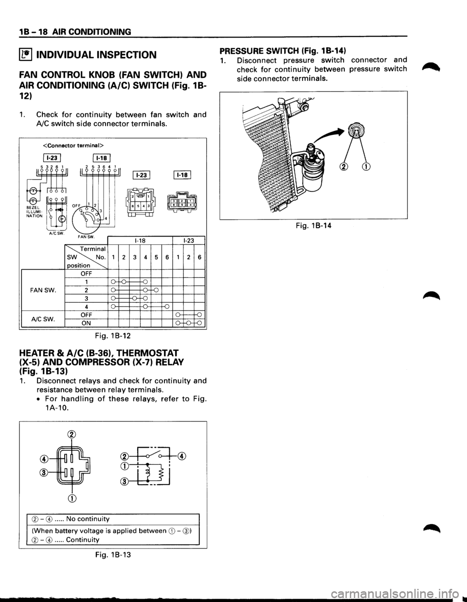
~ INDIVIDUAL INSPECTION
FAN CONTROL KNOB (FAN SWITCH) AND
AIR CONDITIONING (A/C) SWITCH (fig. 1 B-
12)
1. Check for continuity between fan switch and
AJC switch side connector terminals.
ITill [Eill
[fill [Eill ~ 11''''''·11
'"" ~~ -
-~
i'~EHffil ILLUMI-, . cl 3 LI LJ NATION I I 4
L_ _ _j AICSW. FAN SW. 1-18 1-23
~
1
2 3 4 5 6 1 2
n
.
OFF
1 0
FAN SW. 2 [)_ -11--::=:;-
3 o-~ -n. -o
4 [)_ -o
OFF (). f--NCSW. ON [)_
Fig. 18-12
HEATER & A/C (B-36), THERMOSTAT
(X-5) AND COMPRESSOR (X-7) RELAY
(fig. 18-13)
:;,_
6
-f)
-:;::;
1. Disconnect relays and check for continuity and
resistance between
relay terminals.
•
For handling of these relays, refer to Fig.
1A-10.
@
@
®
CD
®-0 ..... No continuity
(When battery voltage is applied between CD-@)
®-0 ..... Continuity
Fig. 18-13
PRESSURE SWITCH (Fig. 18-14)
1. Disconnect pressure switch connector and
check
for continuity between pressure switch
side connector terminals.
Fig. 18-14
Page 73 of 1928
AIR CONDITIONING 1 B -19
ON-VEHICLE SERVICE
GENERAL REPAIR PROCEDURE
Precautions for Replacement or Repair of Air
Conditioning Parts
There are certain procedures, practices and pre
cautions
that should be followed when servicing air
conditioning systems:
• Keep your work area clean.
•
Always wear safety goggle and protective gloves
when working on refrigerant systems.
• Beware of the danger of carbon monoxide fumes
caused by running the engine.
• Beware of discharged refrigerant in enclosed or
improperly ventilated garages.
• Always disconnect the negative battery cable and
discharge and recover the refrigerant
whenever
repairing the air conditioning system.
• When discharging and recovering the refrigerant,
do not allow refrigerant to discharge too fast; it
will draw compressor oil out of the system.
• Keep moisture and contaminants out of the sys
tem.
When disconnecting or removing any lines
or parts, use plugs or caps to close the fittings
immediately.
Never remove the caps or plugs until the lines or
parts are reconnected or installed.
•
When disconnecting or reconnecting the lines,
use
two wrenches to support the line fitting, to
prevent from twisting or other damage.
• Always install new 0-rings whenever a connec
tion is disassembled.
• Before connecting any hoses or lines, apply new
specified compressor oil to the 0-rings.
• When removing and replacing any parts which
require discharging the refrigerant circuit, the
operations described in
this section must be per
formed in the following sequence:
1. Use the J-39500 (ACR4
: HFC-134a Refrigerant
Recovery/Recycling/Recharging/System)
or
equivalent to thoroughly discharge and re
cover
the refrigerant.
2. Remove and replace the defective part.
3.
After evacuation, charge the air conditioning
system and check for leaks.
Repair of Refrigerant Leaks
Refrigerant Line Connections
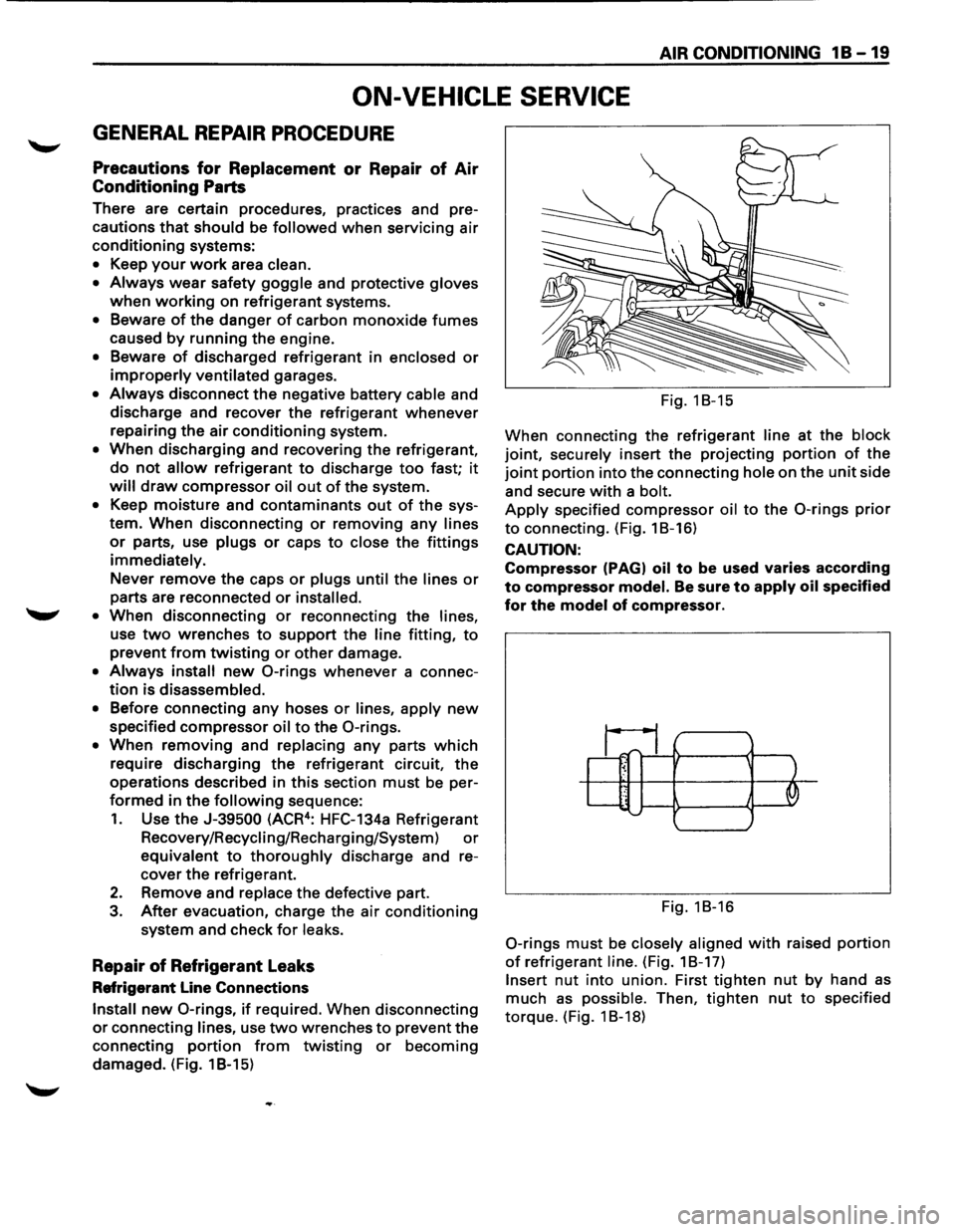
Install new 0-rings, if required. When disconnecting
or connecting lines, use two wrenches to prevent the
connecting
portion from twisting or becoming
damaged. (Fig. 1 B-15) Fig.
18-15
When connecting the refrigerant
line at the block
joint, securely insert the projecting portion of the
joint portion into the connecting hole on the unit side
and secure
with a bolt.
Apply specified compressor oil to the 0-rings prior
to connecting. (Fig. 18-16)
CAUTION:
Compressor (PAGI oil to be used varies according
to compressor model. Be sure to apply oil specified
for the model of compressor.
~1;1_ ~ ' .. J '--......
Fig. 18-16
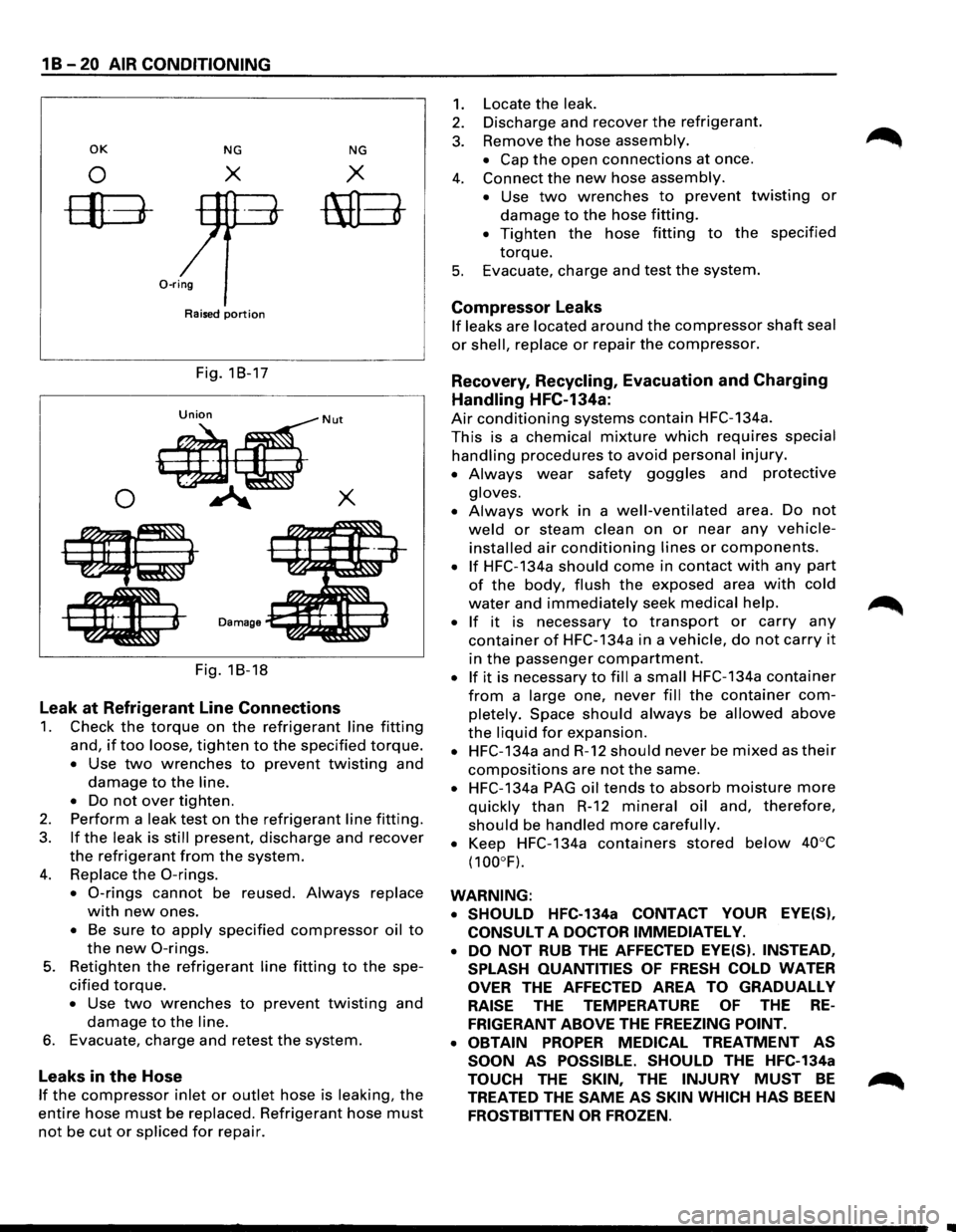
0-rings must be closely aligned with raised portion
of refrigerant line. (Fig. 18-17)
Insert nut into union. First tighten nut by hand as
much as possible. Then, tighten nut to specified
torque. (Fig. 1 8-18)
Page 74 of 1928
1 B -20 AIR CONDITIONING
OK NG NG
0 X X
ffB-mEt
0-ring
Raised portion
Fig. 18-17
0
Fig. 18-18
Leak at Refrigerant Line Connections
1. Check the torque on the refrigerant line fitting
and, if too loose, tighten to the specified torque.
• Use two wrenches to prevent twisting and
damage to the line.
•
Do not over tighten.
2. Perform a leak test on the refrigerant line fitting.
3. If the leak is still present, discharge and recover
the refrigerant from the system.
4. Replace the 0-rings.
• 0-rings cannot be reused. Always replace
with new ones.
• Be sure to apply specified compressor oil to
the new 0-rings.
5. Retighten the refrigerant line fitting to the spe
cified torque.
• Use two wrenches to prevent twisting and
damage to the line.
6. Evacuate, charge and retest the system.
Leaks in the Hose
If the compressor inlet or outlet hose is leaking, the
entire hose must be replaced. Refrigerant hose must
not be cut or spliced for repair.
1.
2.
3.
4.
5.
Locate the leak.
Discharge and recover the refrigerant.
Remove
the hose assembly.
• Cap the open connections at once.
Connect
the new hose assembly.
•
Use two wrenches to prevent twisting or
damage to the hose fitting.
• Tighten the hose fitting to the specified
torque.
Evacuate, charge and test the system.
Compressor Leaks
If leaks are located around the compressor shaft seal
or shell, replace or repair the compressor.
Recovery, Recycling, Evacuation and Charging
Handling HFC-134a:
Air conditioning systems contain HFC-134a.
This is a chemical mixture which requires special
handling procedures to avoid personal injury.
• Always wear safety goggles and protective
gloves.
•
Always work in a well-ventilated area. Do not
weld or steam clean on or near any vehicle
installed air conditioning lines or components.
• If HFC-134a should come in contact with any part
of the body, flush the exposed area with cold
water and immediately seek medical help.
•
If it is necessary to transport or carry any
container of HFC-134a in a vehicle, do not carry it
in the passenger compartment.
• If it is necessary to fill a small HFC-134a container
from a large one, never fill the container com
pletely. Space should always be allowed above
the liquid for expansion.
• HFC-134a and R-12 should never be mixed as their
compositions are not the same.
• HFC-134a PAG oil tends to absorb moisture more
quickly than R-12 mineral oil and, therefore,
should be handled more carefully.
•
Keep HFC-134a containers stored below 40°C
(100°F).
WARNING: • SHOULD
HFC-134a CONTACT YOUR EYE(S),
CONSULT
A DOCTOR IMMEDIATELY.
•
DO NOT RUB THE AFFECTED EYE(S). INSTEAD,
SPLASH QUANTITIES
OF FRESH COLD WATER
OVER THE AFFECTED AREA TO GRADUALLY
RAISE THE TEMPERATURE OF THE RE
FRIGERANT ABOVE THE FREEZING POINT.
• OBTAIN
PROPER MEDICAL TREATMENT AS
SOON
AS POSSIBLE. SHOULD THE HFC-134a
TOUCH THE SKIN, THE INJURY MUST BE
TREATED THE SAME AS SKIN WHICH HAS BEEN
FROSTBITTEN OR FROZEN.
Page 75 of 1928
Refrigerant Recovery
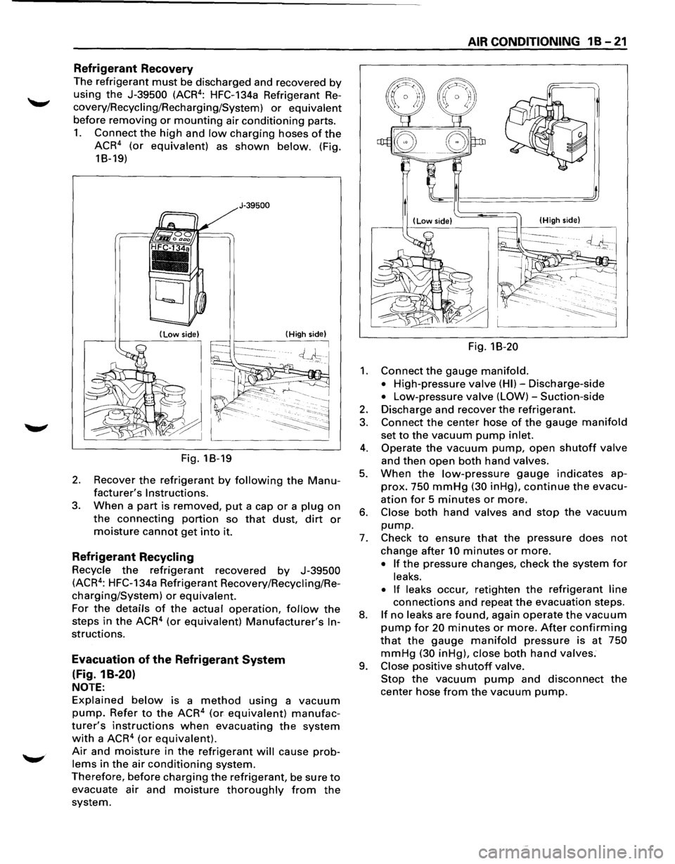
The refrigerant must be discharged and recovered by
using the J-39500 (ACR4
: HFC-134a Refrigerant Re
covery/Recycling/Recharging/System) or equivalent
before removing or mounting air conditioning parts.
1. Connect the high and low charging hoses of the
ACR4 (or equivalent) as shown below. (Fig.
18-19)
J-39500
(High side)
Fig. 18-19
2. Recover the refrigerant by following the Manu
facturer's Instructions.
3. When a part is removed, put a cap or a plug on
the connecting portion so that dust, dirt or
moisture cannot get into it.
Refrigerant Recycling
Recycle the refrigerant recovered by J-39500
(ACR4: HFC-134a Refrigerant Recovery/Recycling/Re
charging/System) or equivalent.
For the details of the actual operation, follow the
steps in the ACR4 (or equivalent) Manufacturer's In
structions.
Evacuation of the Refrigerant System
(Fig. 1 B-20)
NOTE:
Explained below is a method using a vacuum
pump. Refer to the ACR4 (or equivalent) manufac
turer's instructions when evacuating the system
with a ACR4 (or equivalent).
Air and moisture in the refrigerant will cause prob
lems in the air conditioning system.
Therefore,
before charging the refrigerant, be sure to
evacuate air and moisture thoroughly from the
system.
AIR CONDITIONING 1 B -21
Fig. 18-20
1. Connect the gauge manifold.
• High-pressure valve (HI)-Discharge-side
• Low-pressure valve (LOW)-Suction-side
2. Discharge and recover the refrigerant.
3. Connect the center hose of the gauge manifold
set to the vacuum pump inlet.
4. Operate the vacuum pump, open shutoff valve
and then open both hand valves.
5. When the low-pressure gauge indicates ap
prox. 750 mmHg (30 inHg), continue the evacu
ation for 5 minutes or more.
6. Close both hand valves and stop the vacuum
pump.
7. Check to ensure that the pressure does not
change after 10 minutes or more.
• If the pressure changes, check the system for
leaks.
• If leaks
occur, retighten the refrigerant line
connections and repeat the evacuation steps.
8. If no leaks are found, again operate the vacuum
pump for 20 minutes or more. After confirming
that the gauge manifold pressure is at 750
mmHg (30 inHg), close both hand valves;
9. Close positive shutoff valve.
Stop the vacuum pump and disconnect the
center hose from the vacuum pump.
Page 76 of 1928
1 B -22 AIR CONDITIONING
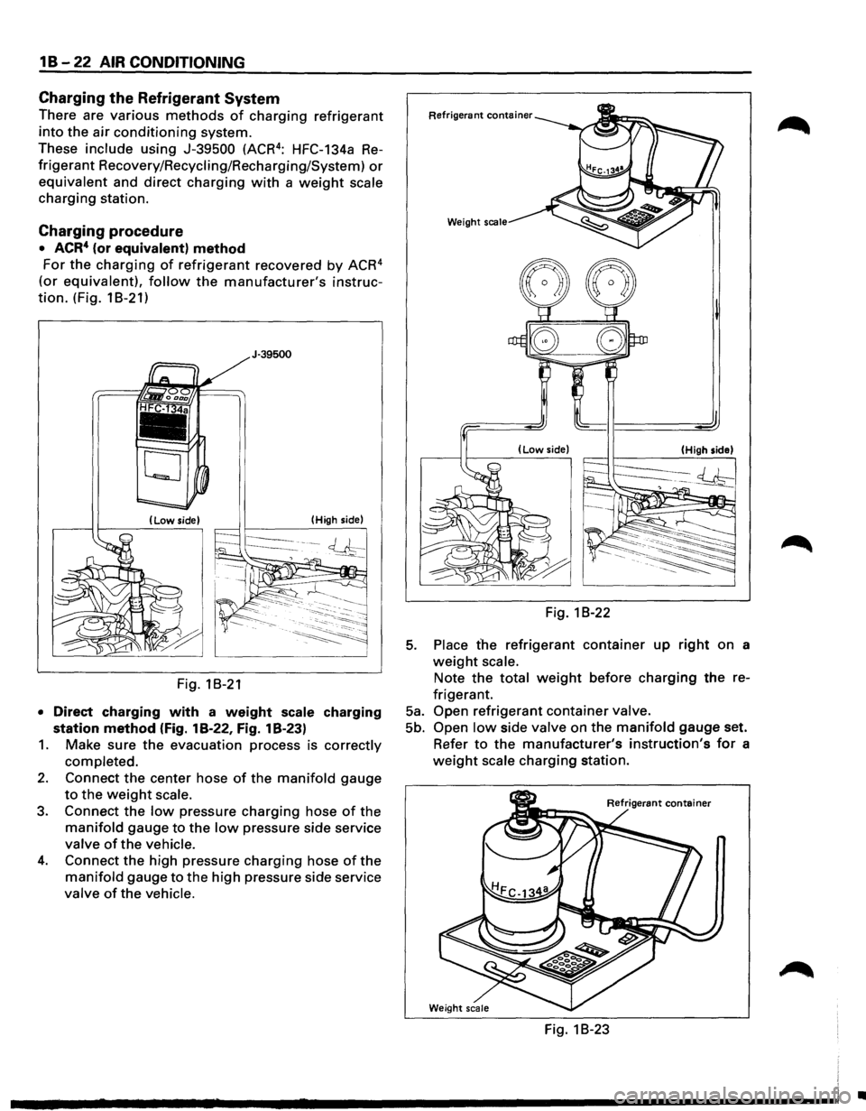
Charging the Refrigerant System
There are various methods of charging refrigerant
into the air conditioning system.
These
include using J-39500 (ACR4 : HFC-134a Re
frigerant Recovery/Recycling/Recharging/System) or
equivalent and direct charging with a weight scale
charging station.
Charging procedure
• ACR4 (or equivalent) method
For the charging of refrigerant recovered by ACR4
(or equivalent), follow the manufacturer's instruc
tion. (Fig. 18-21)
J·39500
(Low side) (High
side)
Fig. 18-21
• Direct charging with a weight scale charging
station method (Fig. 18-22, Fig. 1 B-23)
1. Make sure the evacuation process is correctly
completed.
2. Connect the center hose of the manifold gauge
to the weight scale.
3. Connect the low pressure charging hose of the
manifold gauge to the low pressure side service
valve of the vehicle.
4. Connect the high pressure charging hose of the
manifold gauge to the high pressure side service
valve of the vehicle.
Refrigerant container
Weight scale
(High side)
Fig. 18-22
5. Place the refrigerant container up right on a
weight scale.
Note the total weight before charging the re
frigerant.
Sa. Open refrigerant container valve.
5b. Open low side valve on the manifold gauge set.
Refer
to the manufacturer's instruction's for a
weight scale charging station.
Weight scale
Fig. 18-23
•
Page 77 of 1928
6.
7.
Perform system leak test.
• Charge the system with approx. 200 g (0.44
lbs) of HFC-134a.
• Make sure the high pressure valve of the
manifold gauge is closed.
• Check
to ensure that the degree of pressure
does
not change.
• Check for refrigerant leaks by using a HFC-
134a leak detector.
• If a leak occurs, recover the refrigerant. Repair
the leak, and start all over again from the first
step of evacuation.
If no leaks are found, continue charging re
frigerant to the air conditioning system.
• Charge the refrigerant until the scale reading
decreases
by the amount of the charge
specified.
Specified
amount g (lbs.) I 750 (1.65)
• If charging the system becomes difficult:
( 1) Run the engine at idle and close all the
vehicle doors.
(2) Turn A!C switch "ON".
(3) Set the fan switch to its highest position.
(4) Set air source selector lever to "CIRC".
(5) Slowly open the low side valve on the
manifold gauge set.
WARNING: BE ABSOLUTELY SURE NOT TO
OPEN THE HIGH PRESSURE VALVE OF THE
MANIFOLD GAUGE. SHOULD THE HIGH
PRESSURE VALVE BE OPENED, THE HIGH
PRESSURE REFRIGERANT WOULD FLOW
BACKWARD, AND
THIS MAY CAUSE THE
REFRIGERANT CONTAINER TO BURST.
8. When finished with the refrigerant charging,
close the low pressure valve of the manifold
gauge and container valve.
9. Check for refrigerant leaks.
AIR CONDITIONING 18 -23
Checking
the A/C system
1. Run the engine and close all the vehicle doors.
2. Turn A!C switch "ON", set the fan switch to its
highest position, set air source
lever to "CIRD"
and set temperature lever to full cool position.
3. Check the high and low pressure of the manifold
gauge.
• Immediately after charging refrigerant, both
high and low pressure are slightly high, but
they settle down to the pressure guidelines
shown below:
Ambient temperature: 25-30°C (77 -86°F)
Pressure guidelines:
• High-pressure side;
Approx. 1372.9-1863.3kPa (199.1-270.2psi)
• Low-pressure side;
Approx. 147.1-294.2 kPa (21.3-42.7 psi)
• If an abnormal pressure is found, refer to
"CHECKING REFRIGERANT SYSTEM WITH
MANIFOLD
GAUGE" in this section.
4. Put your hand in front of the air outlet and move
the temperature control lever of the control
panel
to different positions. Check if the outlet
temperature changes as selected by the control
knob.