air condition ISUZU TROOPER 1995 Repair Manual
[x] Cancel search | Manufacturer: ISUZU, Model Year: 1995, Model line: TROOPER, Model: ISUZU TROOPER 1995Pages: 1928
Page 141 of 1928
POWER STEERING SYSTEM TEST
TEST PROCEDURE
Test of fluid pressure in the power steering system is
performed to determine whether
or not the oil pump
and
power steering unit are functioning normally.
The power steering system test is method used to
identify and
isolate hydraulic circuit difficulties. Prior
to performing this test, the following inspections and
corrections,
if necessary, must be made.
[!) INSPECT
• Pump reservoir for proper fluid level.
•
Pump belt for proper tension.
• Pump driver pulley condition.
1. Place a container under the pump to catch the
fluid when disconnecting or connecting the
hoses.
2. With the engine NOT running, disconnect the
pressure hose
at the power steering pump and
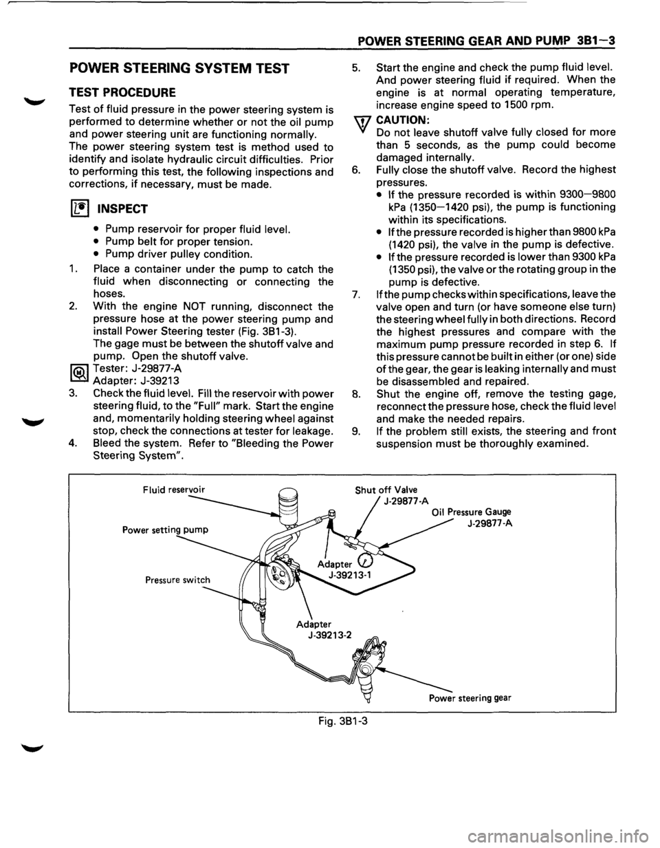
install Power Steering tester (Fig. 3B1-3).
The gage
must be between the shutoff valve and
pump.
Open the shutoff valve.
li5\l Tester: J-29877-A
~ Adapter: J-39213
3. Check the fluid level. Fill the reservoir with power
steering fluid, to the "Full" mark. Start the engine
and,
momentarily holding steering wheel against
stop, check the connections at tester
for leakage.
4. Bleed the system. Refer to "Bleeding the Power
Steering
System".
POWER STEERING GEAR AND PUMP 381-3
5. Start the engine and check the pump fluid level.
And power steering fluid if required. When the
engine is at
normal operating temperature,
increase engine speed to 1500 rpm.
U7 CAUTION:
VI Do not leave shutoff valve fully closed for more
than 5 seconds,
as the pump could become
damaged
internally.
6. Fully close the shutoff valve. Record the highest
pressures.
• If the pressure recorded is within 9300-9800
kPa (1350-1420 psi), the pump is functioning
within its specifications.
• If the pressure recorded is higher than 9800 kPa
(1420 psi), the valve in the pump is defective.
• If the pressure recorded is lower than 9300 kPa
(1350 psi), the valve or the rotating group in the
pump is defective.
7. If the pump checks within specifications, leave the
valve open and turn (or have someone else turn)
the steering
wheel fully in both directions. Record
the highest pressures and compare
with the
maximum pump pressure recorded in step
6. If
this pressure cannot be built in either (or one) side
ofthe gear, the gear is leaking internally and must
be disassembled and repaired.
8. Shut the engine off, remove the testing gage,
reconnect the pressure hose, check the
fluid level
and make the needed repairs.
9. If the problem still exists, the steering and front
suspension must be thoroughly examined.
Shut off Valve
J-29877-A
Oil Pressure Gauge
J-29877-A
Fig. 3B1-3
Page 149 of 1928
![ISUZU TROOPER 1995 Repair Manual (1!] INSPECTION AND REPAIR
Inspect the following parts for wear, damage or any
other abnormal conditions.
• Bearing
• Ball-nut and valve housing
• Sector shaft
• Top cover
• Gear](/img/61/57183/w960_57183-148.png "ISUZU TROOPER 1995 Repair Manual (1!] INSPECTION AND REPAIR
Inspect the following parts for wear, damage or any
other abnormal conditions.
• Bearing
• Ball-nut and valve housing
• Sector shaft
• Top cover
• Gear")
(1!] INSPECTION AND REPAIR
Inspect the following parts for wear, damage or any
other abnormal conditions.
• Bearing
• Ball-nut and valve housing
• Sector shaft
• Top cover
• Gear box
• Needle bearing
• Dust seal
• Seal ring
• Gasket
Ball-nut rotation (fig. 381-18)
Hold the ball nut and valve housing assembly vertically
and see
if the ball-nut lowers by turning smoothly. If
the ball-nut does not lower smoothly, check the worm
shaft for bending and foreign matter.
NOTE:
When testing the ball nut and valve housing assembly,
do not let it travel all the way to the end of worm shaft,
or damage to the ball tubes will result.
• Check sector shaft outside diameter (Fig. 381-
19).
~~~ Limit mm (in) 31.7 (1.25)
Fig. 3B1-18
Fig. 3B1-19
POWER STEERING GEAR AND PUMP 381-11
Seal ring setting (fig. 381-20)
8.
~·
Note the setting direction. Always install a
new part.
Apply a thin coat of power steering fluid to lip of
each part.
Dust seal setting (Fig. 381-20)
r=l • Note the setting direction. Always install a
1.=.1 new part.
l<=l()l • Apply a thin coat of power steering fluid to lip of
each part.
Dust seal
Fig. 3B1-20
Gasket setting (fig. 381-21)
1 .. 1• Note the setting direction.
a:;::::;::] • Apply a thin coat of power steering fluid to lip of
D each part.
Fig.
3B1-21
Page 159 of 1928
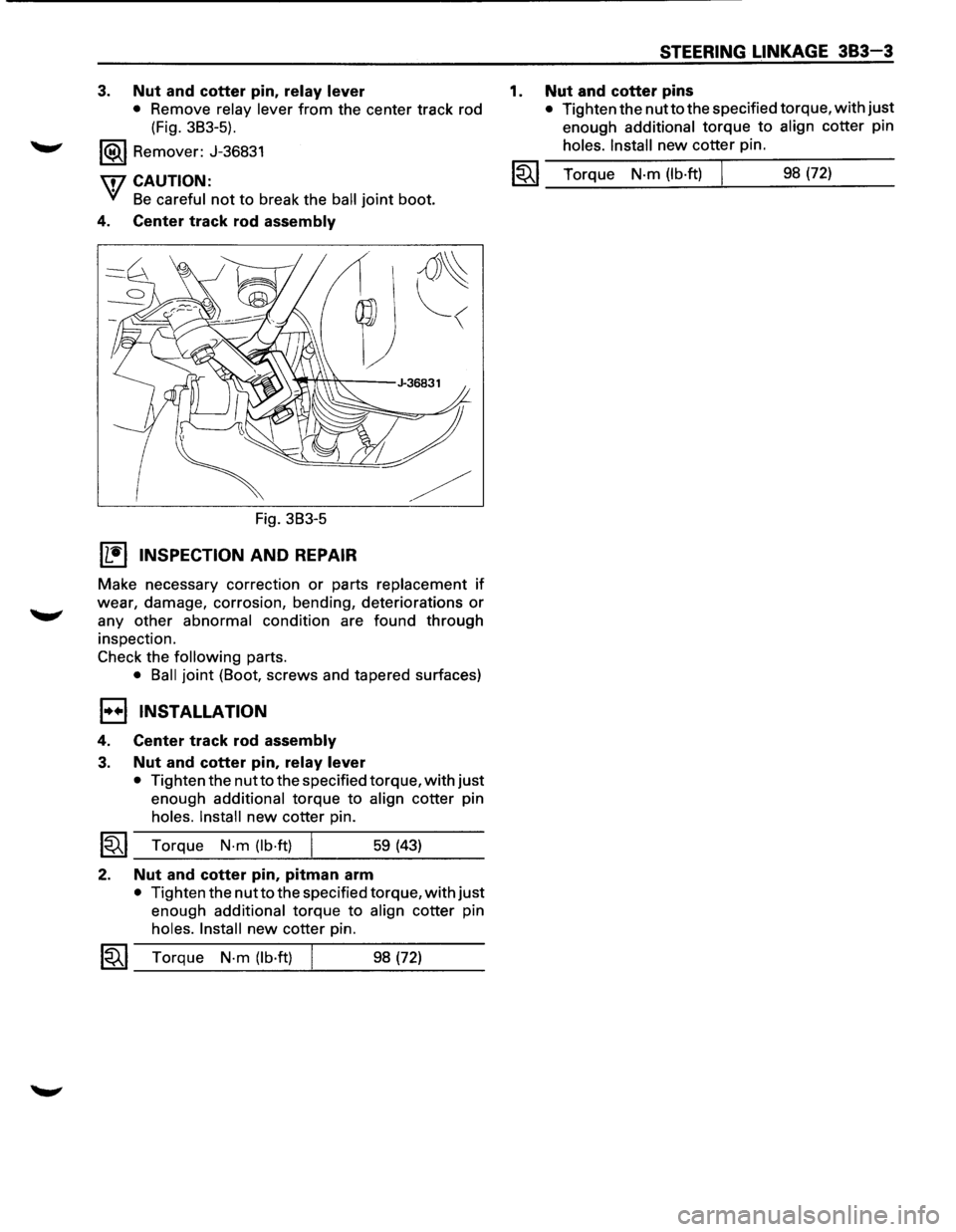
3. Nut and cotter pin, relay lever
• Remove relay lever from the center track rod
(Fig. 3B3-5).
1®.1 Remover: J-36831
\flCAUTION:
'VI Be careful not to break the ball joint boot.
4. Center track rod assembly
Fig. 3B3-5
Wtl INSPECTION AND REPAIR
~
Make necessary correction or parts replacement if
wear, damage, corrosion, bending, deteriorations or
any other abnormal condition are found through
inspection.
Check the
following parts.
• Ball joint (Boot, screws and tapered surfaces)
1••1 INSTALLATION
4. Center track rod assembly
3. Nut and cotter pin, relay lever
• Tighten the nutto the specified torque, with just
enough additional torque to align cotter pin
holes. Install new cotter pin.
~~~ Torque N·m (lb·ft) 59 (43)
2. Nut and cotter pin, pitman arm
• Tighten the nut to the specified torque, with just
enough additional torque to align cotter pin
holes. Install new cotter pin.
1~1 Torque N-m (lb·ft) 98 (72)
1.
STEERING LINKAGE 383-3
Nut and cotter pins
• Tighten the nutto the specified torque, with just
enough
additional torque to align cotter pin
holes. Install new cotter pin.
I~I_T_o_rq..;...u_e_N_·m_(l_b_·ft_) ___t_ ___ 9_8_(7_2_) __ _
Page 161 of 1928
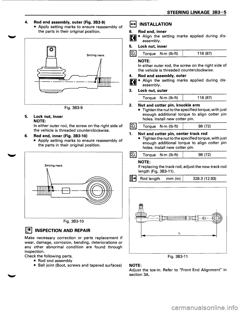
4. Rod end assembly, outer (Fig. 383-9)
• Apply setting marks to ensure reassembly of
the parts in their original position.
Setting mark
Fig. 3B3-9
5. Lock nut, inner
NOTE:
6.
In either outer rod, the screw on the right side of
the vehicle is threaded counterclockwise.
Rod end, inner (Fig. 383-1 O)
• Apply setting marks to ensure reassembly of
the parts in their original position.
Setting mark
--B--
Fig. 3B3-10
(1!] INSPECTION AND REPAIR
Make necessary correction or parts replacement if
wear, damage, corrosion, bending, deteriorations or
any other abnormal condition are found through
inspection.
Check the
following parts.
• Rod end assembly
STEERING LINKAGE 383-5
1••1 INSTALLATION
6. Rod end, inner
IP.il • Align the setting marks applied during dis-
~ assembly.
5. Lock nut, inner
~~~ Torque N·m (lb·ft) 118 (87)
NOTE:
In either outer rod, the screw on the right side of
the vehicle is threaded counterclockwise.
4. Rod end assembly, outer
IP.il • Align the setting marks applied during dis-
~ assembly.
3. Lock nut, outer
Torque N·m (lb·ft) 118 (87)
2. Nut and cotter pin, knuckle arm
• Tighten the nutto the specified torque, with just
enough additional torque to align cotter pin
holes. Install new cotter pin.
~~~ Torque N·m (lb·ft) ___ ______._ ___ _ 98 (72)
1. Nut and cotter pin, center track rod
• Tighten the nutto the specified torque, with just
enough additional torque to align cotter pin
holes. Install new cotter pin.
~~~ Torque N·m (lb·ft) 98 (72)
NOTE:
If replacing
the track rod, adjust the new track rod
length (Fig. 3B3-11).
I~EI Rod length mm (in) I 328.3 (12.93)
L
Fig. 3B3-11
• Ball joint (Boot, screws and tapered surfaces) NOTE:
Adjust the toe-in. Refer to "Front End Alignment" in
section 3A.
Page 167 of 1928
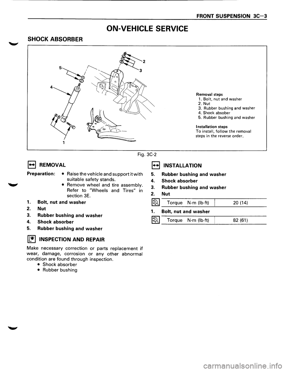
FRONT SUSPENSION 3C-3
ON-VEHICLE SERVICE
SHOCK ABSORBER
Fig. 3C-2
1••1 REMOVAL
Preparation: • Raise the vehicle and support it with
suitable safety stands.
'W' • Remove wheel and tire assembly.
Refer to "Wheels and Tires" in
section
3E.
1. Bolt, nut and washer
2. Nut
3. Rubber bushing and washer
4. Shock absorber
5. Rubber bushing and washer
IL'it'l INSPECTION AND REPAIR
Make necessary correction or parts replacement if
wear, damage, corrosion or any other abnormal
condition are found through inspection.
• Shock absorber
• Rubber bushing
EJ
5.
4.
3.
2.
~
1.
~
Removal steps
1.
Bolt, nut and washer 2. Nut
3. Rubber bushing and washer
4.
Shock absober 5. Rubber bushing and washer
Installation steps To install, follow the removal steps in the reverse order.
INSTALLATION
Rubber bushing and washer
Shock absorber
Rubber bushing and washer
Nut
Torque N-m (lb·ft) 20 (14)
Bolt, nut and washer
Torque N-m (lb·ft) 82 (61)
Page 168 of 1928
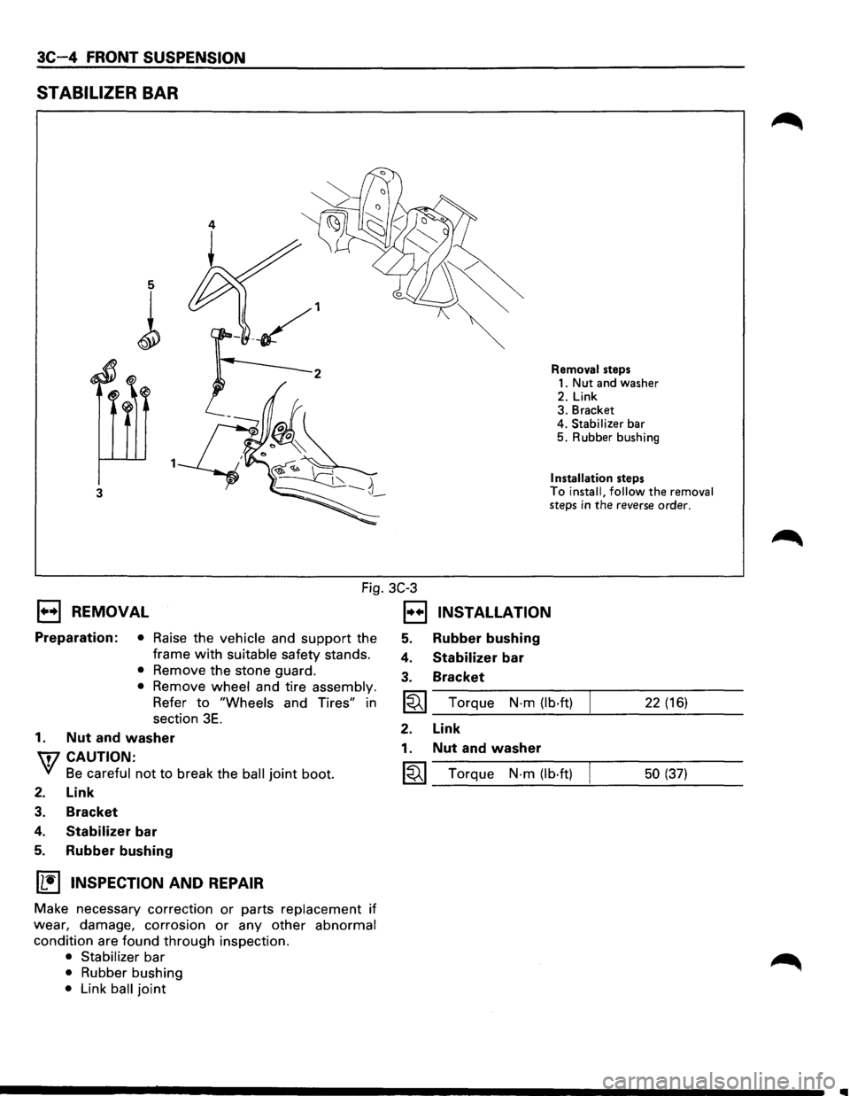
3C-4 FRONT SUSPENSION
STABILIZER BAR
5
l
3
Removal steps
1. Nut and washer
2. Link 3. Bracket
4. Stabilizer bar 5. Rubber bushing
Installation steps To install, follow the removal steps in the reverse order.
Fig. 3C-3
1••1 REMOVAL
Preparation: • Raise the vehicle and support the
frame
with suitable safety stands.
• Remove the stone guard.
• Remove wheel and tire assembly.
Refer to "Wheels and Tires" in
section
3E.
1. Nut and washer
W CAUTION:
VI Be careful not to break the ball joint boot.
2. Link
3. Bracket
4. Stabilizer bar
5. Rubber bushing
~ INSPECTION AND REPAIR
Make necessary correction or parts replacement if
wear, damage, corrosion or any other abnormal
condition are found through inspection.
• Stabilizer bar
• Rubber bushing
• Link ball joint
1••1 INSTALLATION
5. Rubber bushing
4. Stabilizer bar
3. Bracket
~ Torque N·m (lb·ft) 22 (16)
2. Link
1. Nut and washer
~ Torque N-m (lb·ft) 50 (37)
..
Page 170 of 1928
![ISUZU TROOPER 1995 Repair Manual 3C-6 FRONT SUSPENSION
(L!] INSPECTION AND REPAIR
Make necessary correction or parts replacement if
wear, damage, corrosion or any other abnormal
condition are found through inspection.
Ch](/img/61/57183/w960_57183-169.png "ISUZU TROOPER 1995 Repair Manual 3C-6 FRONT SUSPENSION
(L!] INSPECTION AND REPAIR
Make necessary correction or parts replacement if
wear, damage, corrosion or any other abnormal
condition are found through inspection.
Ch")
3C-6 FRONT SUSPENSION
(L!] INSPECTION AND REPAIR
Make necessary correction or parts replacement if
wear, damage, corrosion or any other abnormal
condition are found through inspection.
Check the following parts:
• Torsion bar
• Height control arm
• Adjust bolt
• Rubber seat
1•+1 INSTALLATION
3. Torsion bar
8 • Make sure the bars are on their correct
respective sides (Fig.
3C-8).
1-ool • Apply grease to the serrated portions.
• Align the setting marks (Fig. 3C-9).
Fig. 3C-8
Fig. 3C-9
2. Height control arm
§]•
u:
Apply grease to the portion that fits into the
bracket.
Align the setting marks (Fig. 3C-1 0).
Apply grease to the bolt portion of the end
piece.
r::=;] • Apply grease to the portion of the seat that fits
D into the bracket (Fig. 3C-11 ).
1-ool • Apply grease to the serrated portions.
Fig.
3C-10
Fig. 3C-11
1. Adjust bolt and seat (Fig. 3C-12)
• Turn the adjust bolt to the setting mark applied
during disassembly.
NOTE:
Adjust the trim height. Refer to "Front End Alignment"
in section 3A.
Setting mark
Fig. 3C-12
IIIII
Page 172 of 1928
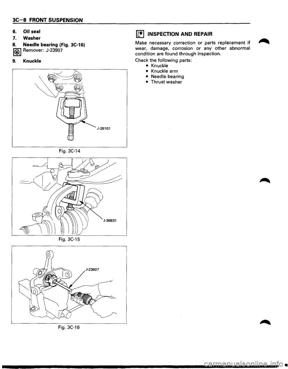
3C-8 FRONT SUSPENSION
6. Oil seal
7. Washer
8. Needle bearing (Fig. 3C-16)
1®.1 Remover: J-23907
9. Knuckle
Fig. 3C-14
Fig. 3C-15
Fig. 3C-16
J-29107
11!) INSPECTION AND REPAIR
Make necessary correction or parts replacement if ~
wear, damage, corrosion or any other abnormal
condition are found through inspection.
Check the
following parts:
• Knuckle
• Knuckle arm
• Needle bearing
• Thrust washer
•
Page 175 of 1928
\fl CAUTION:
'V Be careful not to break the ball joint boot.
3. Upper ball joint
4. Bolt and plate
5. Nut assembly
6. Camber shims
• Note the positions and number of shims.
7. Caster shims
• Note the positions and number of shims.
8. Upper control arm assembly
9. Nut
10. Plate
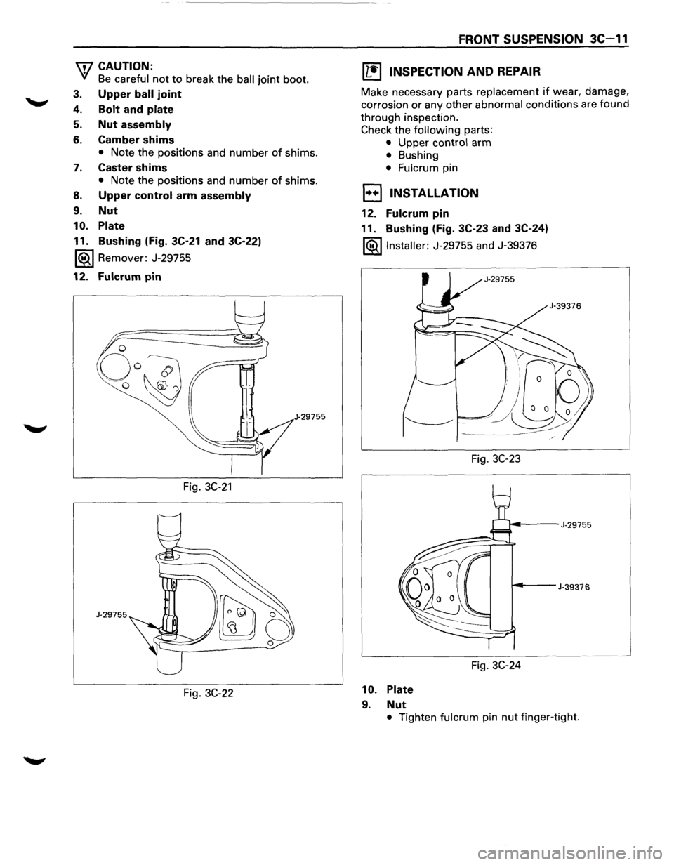
11. Bushing (Fig. 3C-21 and 3C-22)
1®.1 Remover: J-29755
12. Fulcrum pin
J·29755
Fig. 3C-21
J-29755
Fig. 3C-22
FRONT SUSPENSION 3C-11
IL•I INSPECTION AND REPAIR
Make necessary parts replacement if wear, damage,
corrosion or any other abnormal conditions are found
through inspection.
Check the following parts:
• Upper control arm
• Bushing
• Fulcrum pin
1••1 INSTALLATION
12. Fulcrum pin
11. Bushing (Fig. 3C-23 and 3C-24)
l®.llnstaller: J-29755 and J-39376
Fig.
3C-23
~---J-29755
~--J-39376
Fig. 3C-24
10. Plate
9. Nut
• Tighten fulcrum pin nut finger-tight.
Page 178 of 1928
3C-14 FRONT SUSPENSION
9. Bolt, rear
10. Lower control arm
11.
Bolt, torsion bar arm
12.
Bolt, lower ball joint
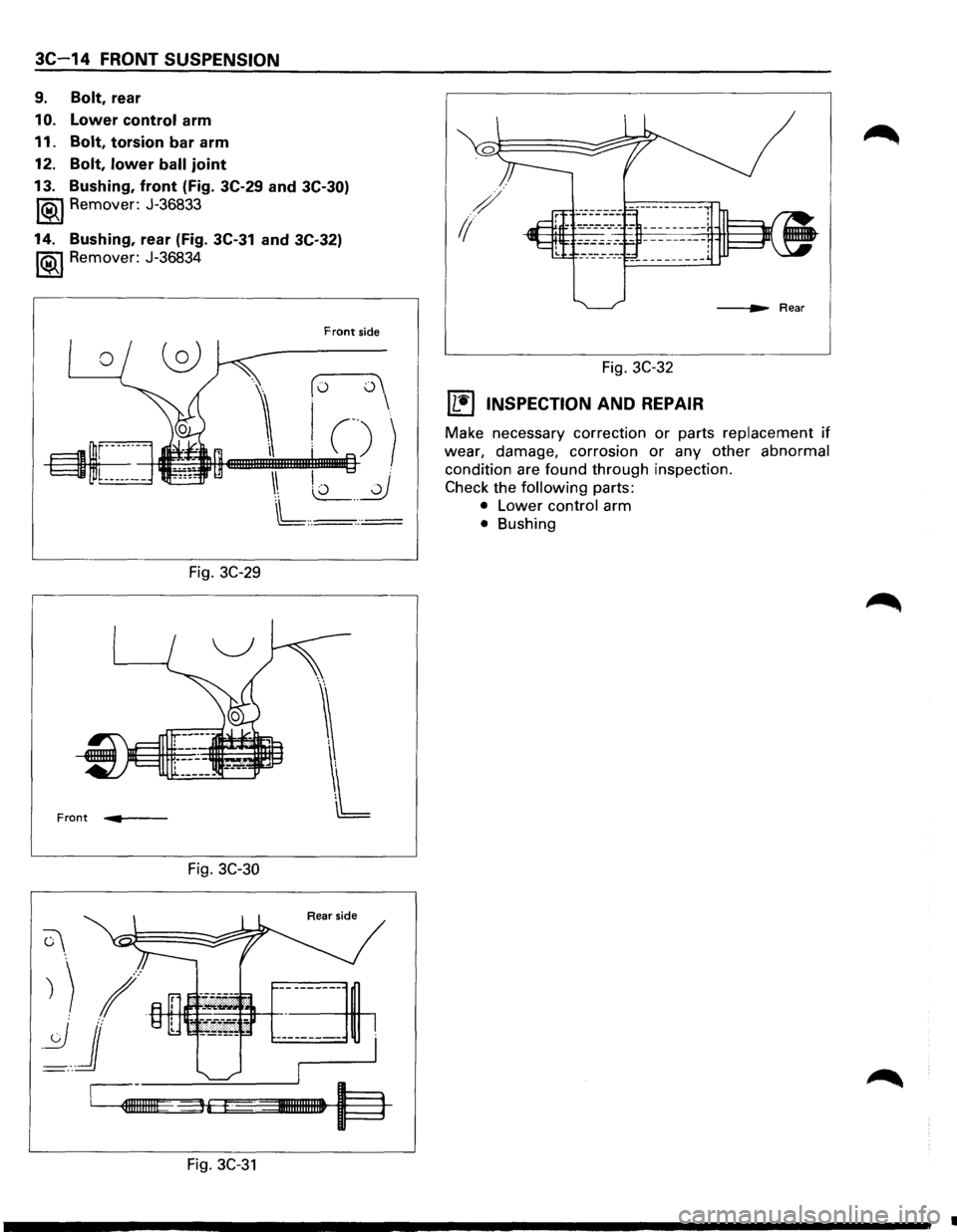
13. Bushing, front (Fig. 3C-29 and
3C-30)
1®.1 Remover: J-36833
14. Bushing, rear (Fig. 3C-31 and 3C-32)
1®..1 Remover: J-36834
Fig. 3C-29
Front .... .,. __ _
Fig. 3C-30
C\.
Front side
(o o
I C))
\ L2_ __ _0
L,._· .:=
Rear side
) ) 1+-H!-H++----+-ff--+-----------
~j r---------
~I~IIIIIIE36 I· %31111111111111 l==l
Fig. 3C-31
/
1/
Fig. 3C-32
(1!] INSPECTION AND REPAIR
Make necessary correction or parts replacement if
wear, damage, corrosion or any other abnormal
condition are found through inspection.
Check the
following parts:
• Lower control arm
• Bushing
•