air condition ISUZU TROOPER 1995 Manual PDF
[x] Cancel search | Manufacturer: ISUZU, Model Year: 1995, Model line: TROOPER, Model: ISUZU TROOPER 1995Pages: 1928
Page 181 of 1928
[L!) INSPECTION AND REPAIR
Make necessary parts replacement if wear, damage,
corrosion
or any other abnormal conditions are found
through inspection.
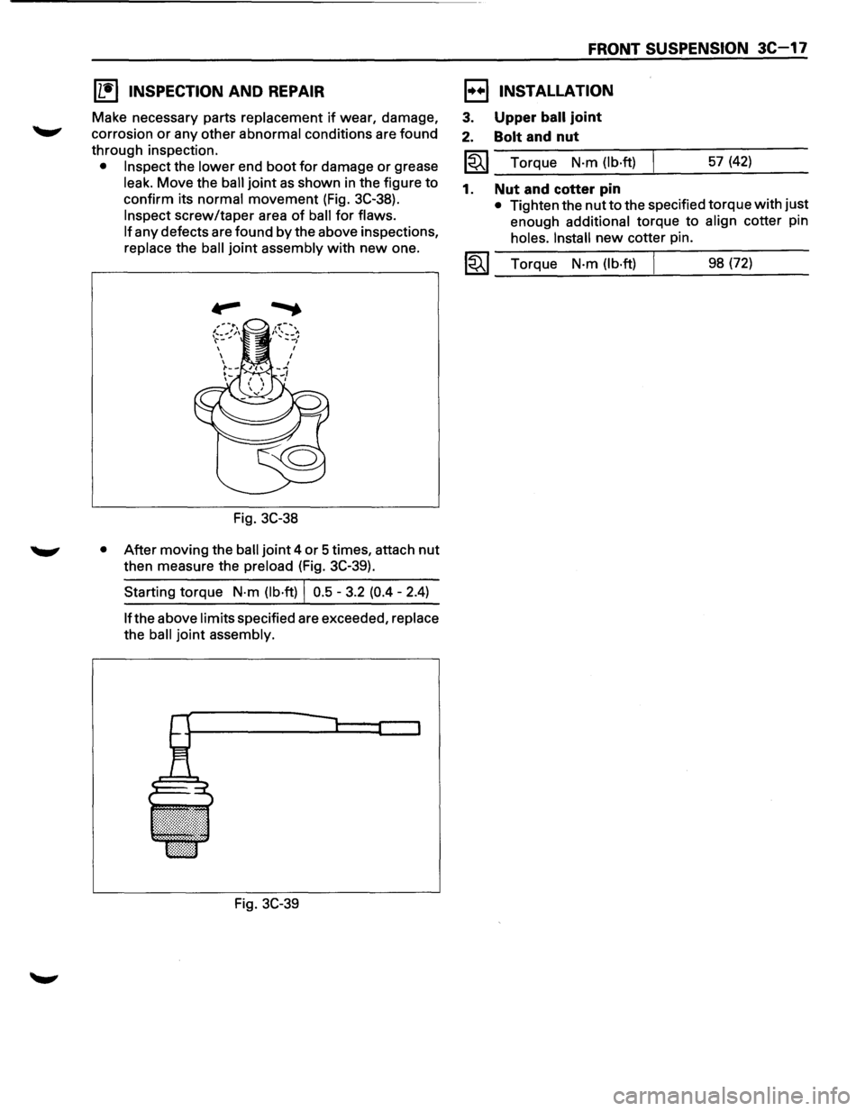
• Inspect the lower end boot for damage or grease
leak. Move the ball joint as shown in the figure to
confirm its normal movement (Fig. 3C-38).
Inspect screw/taper area of ball for flaws.
If
any defects are found by the above inspections,
replace the ball joint assembly with new one.
Fig. 3C-38
• After moving the ball joint 4 or 5 times, attach nut
then measure the preload (Fig. 3C-39).
Starting torque
N·m (lb·ft) I 0.5 -3.2 (0.4 - 2.4)
lfthe above limits specified are exceeded, replace
the ball joint assembly.
Fig. 3C-39
FRONT SUSPENSION 3C-17
1••1 INSTALLATION
3. Upper ball joint
2. Bolt and nut
~~~--T~o_rq~u_e __ N_·m~(l_b_·ft~)_L _____ 5_7_(4_2_) ____ _
1. Nut and cotter pin
• Tighten the nut to the specified torque with just
enough
additional torque to align cotter pin
holes. Install new cotter pin.
1-"i"' I Torque N·m (lb·ft) j 98 (72) ~---~--~~--------
Page 183 of 1928
I L•IINSPECTION AND REPAIR
Make necessary parts replacement if wear, damage,
corrosion
or any other abnormal condition are found
through inspection.
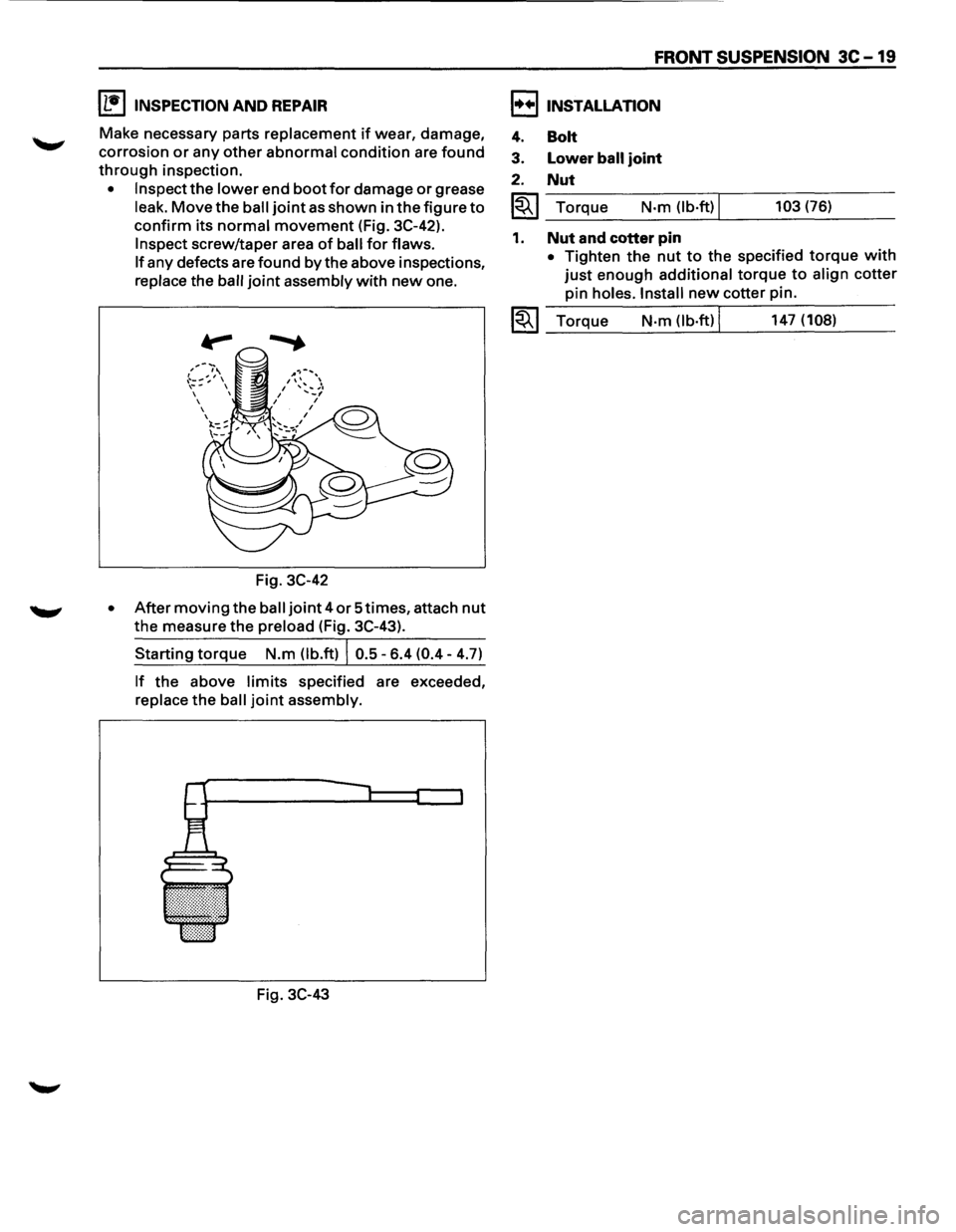
• Inspect the lower end boot for damage or grease
leak.
Move the ball joint as shown in the figure to
confirm its normal movement (Fig. 3C-42).
Inspect screw/taper area of ball for flaws.
If
any defects are found by the above inspections,
replace the ball
joint assembly with new one.
,--~:_,.--,',\ ,-...
~ .. :::: , \~-,
Fig. 3C-42
• After moving the ball joint 4 or Stimes, attach nut
the measure the preload (Fig. 3C-43).
Starting torque N.m (lb.ft) I 0.5-6.4 (0.4-4.7)
If the above limits specified are exceeded,
replace
the ball joint assembly.
Fig.
3C-43
FRONT SUSPENSION 3C-19
I••! INSTALLATION
4.
3.
2.
Bolt
Lower ball joint
Nut
I~I_To_r_:_q_ue __ N_·m_O_b_·ft_) Ll ___ 10_3_(7_6_) __ _
1. Nut and cotter pin
• Tighten the nut to the specified torque with
just enough additional torque to align cotter
pin
holes. Install new cotter pin.
~~~ Torque N·m (lb·ft) I 147 (108) --~----~-----------
Page 189 of 1928
REAR SUSPENSION 30-3
ON-VEHICLE SERVICE
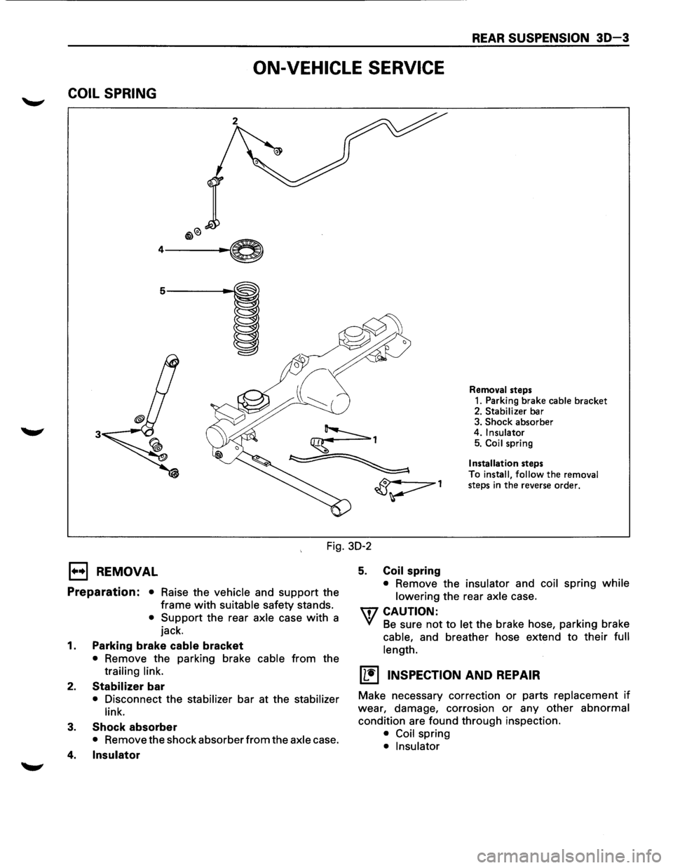
COIL SPRING
3
Removal steps
1. Parking brake cable bracket 2. Stabilizer bar
3. Shock absorber
4. Insulator 5. Coil spring
Installation steps
To install,
follow the removal
steps in the reverse order.
Fig. 30-2
E) REMOVAL
Preparation: • Raise the vehicle and support the
frame
with suitable safety stands.
• Support the rear axle case with a
jack.
1. Parking brake cable bracket
• Remove the parking brake cable from the
trailing link.
2. Stabilizer bar
• Disconnect the stabilizer bar at the stabilizer
link.
3. Shock absorber
• Remove the shock absorber from the axle case.
4. Insulator
5. Coil spring
• Remove the insulator and coil spring while
lowering
the rear axle case.
U7 CAUTION:
VI Be sure not to let the brake hose, parking brake
cable, and breather hose extend to their full
length.
(L!] INSPECTION AND REPAIR
Make necessary correction or parts replacement if
wear, damage, corrosion or any other abnormal
condition are found through inspection.
• Coil spring
• Insulator
Page 191 of 1928
SHOCK ABSORBER
REAR SUSPENSION 30-5
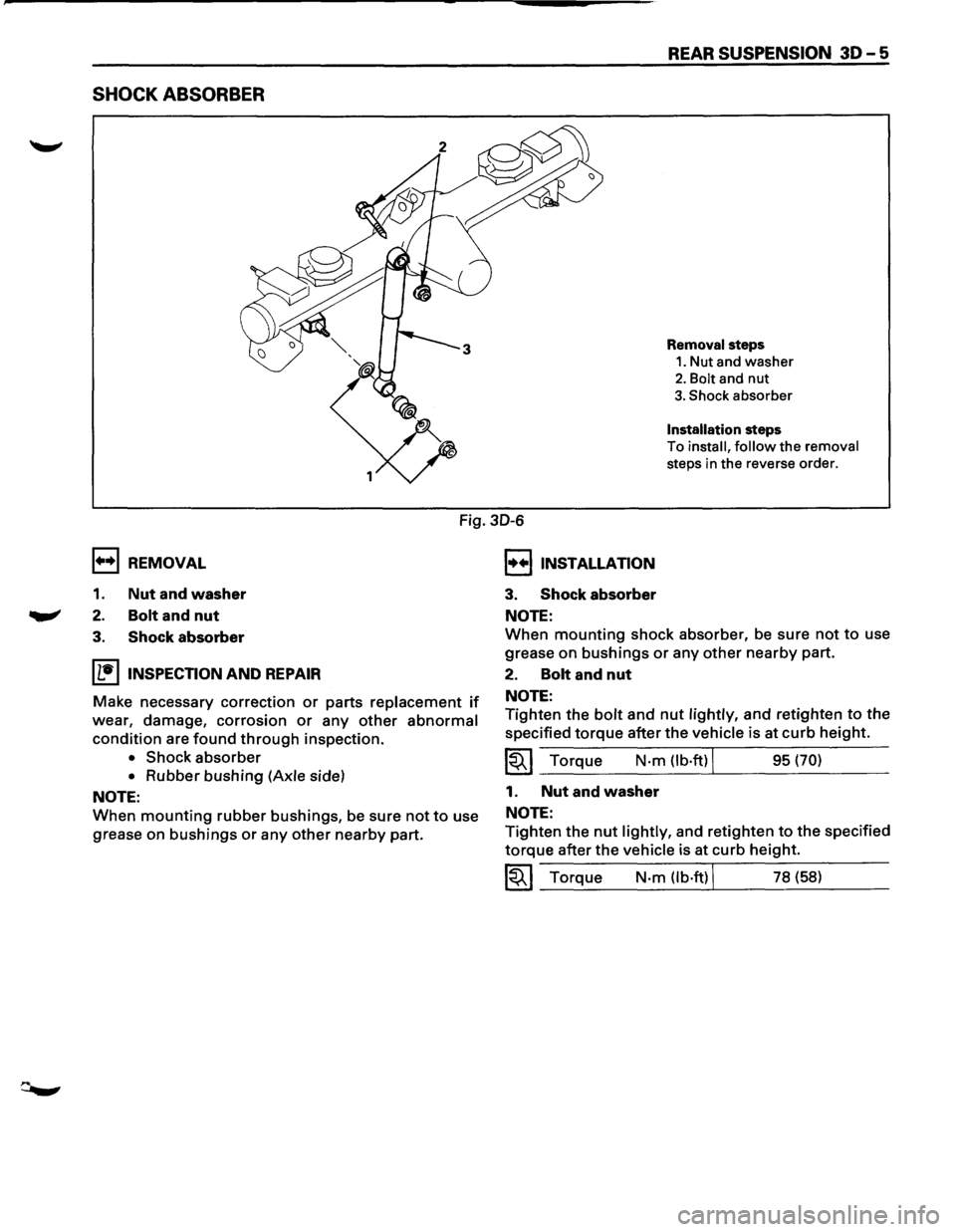
Removal steps
1. Nut and washer
2. Bolt and nut
3. Shock absorber
Installation steps
To
install, follow the removal
steps in the reverse order.
1++1 REMOVAL
1. Nut and washer
2. Bolt and nut
Fig. 30-6
I••IINSTALLATION
3. Shock absorber
NOTE:
3. Shock absorber
IL•IINSPECTION AND REPAIR
Make necessary correction or parts replacement if
wear, damage, corrosion or any other abnormal
condition are found through inspection.
• Shock absorber
• Rubber bushing (Axle side)
NOTE:
When mounting rubber bushings, be sure not to use
grease
on bushings or any other nearby part.
When mounting shock absorber, be sure not to use
grease
on bushings or any other nearby part.
2. Bolt and nut
NOTE:
Tighten the bolt and nut lightly, and retighten to the
specified torque after the vehicle is at curb height.
~~~ Torque N·m (lb·ftl J 95 (70)
1. Nut and washer
NOTE:
Tighten the nut lightly, and retighten to the specified
torque after the vehicle is at curb height.
~~~ Torque N·m (lb·ftl J 78 (58)
Page 192 of 1928
···------
30-6 REAR SUSPENSION
TRAILING LINK
2
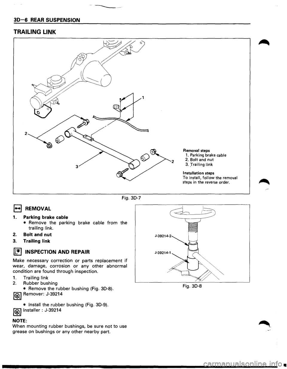
Fig. 30-7
l••l REMOVAL
1. Parking brake cable
• Remove the parking brake cable from the
trailing link.
2. Bolt and nut
3. Trailing link
IL•I INSPECTION AND REPAIR
Make necessary correction or parts replacement if
wear, damage, corrosion or any other abnormal
condition are found through inspection.
1. Trailing link
2. Rubber bushing
• Remove the rubber bushing (Fig. 30-8).
1®..1 Remover: J-39214
• Install the rubber bushing (Fig. 30-9).
!®I Installer : J-39214
NOTE:
When mounting rubber bushings, be sure not to use
grease on bushings
or any other nearby part.
2
J-39214·2
J-39214·1
Removal steps 1. Parking brake cable 2. Bolt and nut
3. :rrailing link
I
nsta llatio n steps
To install, follow the removal steps in the reverse order. ~
..----- 1-~
Fig. 30-8
•
Page 194 of 1928
30-8 REAR SUSPENSION
CENTER LINK
2
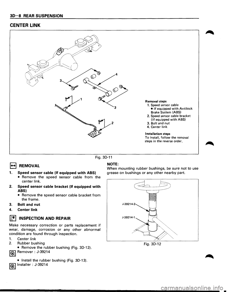
Removal steps
1. Speed sensor cable
• If equipped with Antilock Brake System (ABS)
2. Speed sensor
cable bracket (If equipped with ABS)
3.
Bolt and nut 4. Center link
Installation
steps
To
install, follow the removal steps in the reverse order.
1•+1 REMOVAL
Fig. 30-11
NOTE:
1.
2.
3.
Speed sensor cable (If equipped with ABS)
• Remove the speed sensor cable from the
center
link.
Speed sensor cable bracket (If equipped with
ABS)
• Remove the speed sensor cable bracket from
the frame.
Bolt and nut
4. Center link
~ INSPECTION AND REPAIR
Make necessary correction or parts replacement if
wear, damage, corrosion or any other abnormal
condition are found through inspection.
1. Center link
2. Rubber bushing
• Remove the rubber bushing (Fig. 30-12).
1®1 Remover : J-39214
• Install the rubber bushing (Fig. 30-13).
!®..I Installer : J-39214
When mounting rubber bushings, be sure not to use
grease on bushings
or any other nearby part.
J-39214-2
J-39214·1
Fig. 30-12
..
Page 196 of 1928
30-10 REAR SUSPENSION
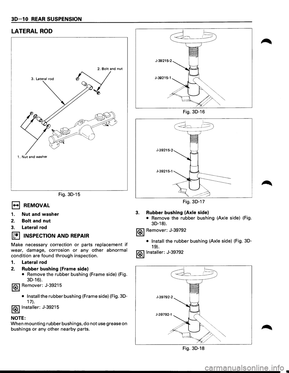
LATERAL ROD
3. Latera I rod
1. Nut
and washer
Fig. 30-15
EJ REMOVAL
1. Nut and washer
2. Bolt and nut
3. Lateral rod
~ INSPECTION AND REPAIR
Make necessary correction or parts replacement if
wear, damage, corrosion or any other abnormal
condition are found through inspection.
1.
Lateral rod
2. Rubber bushing (Frame side)
• Remove the rubber bushing (Frame side) (Fig.
30-16).
1®..1 Remover: J-39215
• Install the rubber bushing (Frame side) (Fig. 30-
17).
l®..llnstaller: J-39215
NOTE:
When mounting rubber bushings, do not use grease on
bushings
or any other nearby parts. Fig.
30-16
J-39215-2
J-39215·1
Fig. 30-17
3. Rubber bushing (Axle side)
• Remove the rubber bushing (Axle side) (Fig.
30-18).
1®..1 Remover: J-39792
• Install the rubber bushing (Axle side) (Fig. 30-
19).
l®..llnstaller: J-39792
Fig. 30-18
Page 197 of 1928
J-39792-1
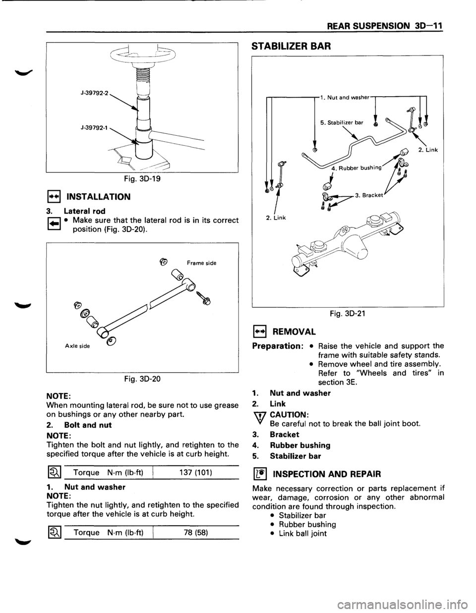
Fig. 30-19
1•+1 INSTALLATION
3. Lateral rod
~ • Make sure that the lateral rod is in its correct
~ position (Fig. 30-20).
Frame side
Axle side
Fig. 30-20
NOTE:
When mounting lateral rod, be sure not to use grease
on bushings
or any other nearby part.
2. Bolt and nut
NOTE:
Tighten the bolt and nut lightly, and retighten to the
specified torque after the
vehicle is at curb height.
~~~ Torque N·m (lb·ft)
1. Nut and washer
NOTE:
137 (101)
Tighten the nut lightly, and retighten to the specified
torque after the
vehicle is at curb height.
1~1 Torque N·m (lb·ft) 78 (58)
REAR SUSPENSION 30-11
STABILIZER BAR
2. Link
Fig. 30-21
EJ REMOVAL
Preparation: • Raise the vehicle and support the
frame
with suitable safety stands.
• Remove wheel and tire assembly.
Refer
to "Wheels and tires" in
section
3E.
1. Nut and washer
2. Link
\fl CAUTION:
VI Be careful not to break the ball joint boot.
3. Bracket
4. Rubber bushing
5. Stabilizer bar
[!] INSPECTION AND REPAIR
Make necessary correction or parts replacement if
wear, damage, corrosion or any other abnormal
condition are found through inspection.
• Stabilizer bar
• Rubber bushing
• Link ball joint
Page 201 of 1928
WHEELS AND TIRES 3E-1
SECTION 3E
WHEELS AND TIRES
W CAUTION:
When fasteners are removed, always reinstall them at the same location from which they were removed.
If a fastener needs to be replaced, use the correct part number fastener for that application. If the correct
part
number fastener is not available, a fastener of equal size and strength (or stronger) may be used.
Fasteners
that are not reused, and those requiring thread locking compound, will be called out. The correct
torque value must be used when installing fasteners that require it. If the above conditions are not
followed, parts or system damage could result.
CONTENTS
General Description . . . . . . . . . . . . . . . . . . . . . . . . . . . . . . . 3 E -1 Unit Repair .......................................... 3E-7
Diagnosis ........................................... 3E-2 Tires ............................................... 3E-7
Irregular and Premature Wear ................ 3E-2 Wheels ............................................ 3E-7
Inflation of Tires ................................. 3 E- 3 General Balance Procedure ................... 3E-8
Diagnosis List. . . . . . . . . . . . . . . . . . . . . . . . . . . . . . . . . . . . 3 E- 3 Balancing Wheel and Tire ...................... 3E-8
On-Vehicle Service ................................ 3E-6 Main Data and Specifications .................... 3E-9
Wheels ............................................ 3E-6 General Specifications ......................... 3E-9
Torque Specifications .......................... 3E-9
GENERAL DESCRIPTION
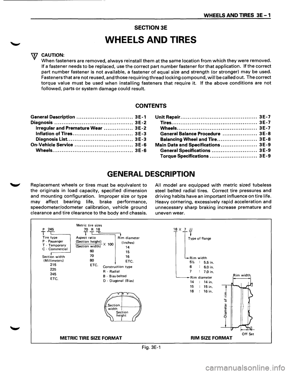
Replacement wheels or tires must be equivalent to
the originals in load capacity, specified dimension
and mounting configuration. Improper size or type
may affect bearing life, brake performance,
speedometer/odometer calibration, vehicle ground
clearance and tire clearance to the body and chassis.
p 245
T Tire type P -Passenger T -Temporary C -Commercial
Section
width (Millimeters) 215 225
245
ETC.
Metric tire sizes 70 R 16 T ,...
Aspect ratio I Rim diameter
(Section height)
(Section
width) X 100 (Inches)
14 60 70
80 ETC.
15
16 ETC.
Construction type
R-Radial
B - Bias-belted
D - Diagonal (Bias)
METRIC TIRE SIZE FORMAT
All model are equipped with metric sized tubeless
steel belted radial
tires. Correct tire pressures and
driving habits have an important influence on tire life.
Heavy cornering, excessively rapid acceleration and
unnecessary sharp braking increase
premature and
uneven wear.
16 X 7 JJ
I
~pe of flange
Rim width 5% 5.5 in.
6 6.0 in. 7 7.0 in.
Rim diameter Rim width
14 14 in. 15 15 in. 16 : 16 in.
I Off Set RIM SIZE FORMAT
Fig. 3E-1
Page 211 of 1928
SUPPLEMENTAL RESTRAINT SYSTEM (SRSl STEERING WHEEL & COLUMN 3F4-1
SECTION 3F4
SUPPLEMENTAL RESTRAINT SYSTEM
STEERING
WHEEL & COLUMN
W CAUTION:
When fasteners are removed, always reinstall them at the same location from which they were removed.
If a fastener needs to be replaced, use the correct part number fastener for that application. If the correct
part
number fastener is not available, a fastener of equal size and strength (or stronger) may be used.
Fasteners
that are not reused, and those requiring thread locking compound, will be called out. The correct
torque value must be used when installing fasteners that require it. If the above conditions are not
followed, parts or system damage could result.
CONTENTS
General Description .......................................... 3F4-1
Lock Cylinder Replacement ......................... 3F4-10
On-Vehicle Service
............................................ 3F4-2 Steering Column Replacement .................... 3F4-13
Special Service Precaution ........................... 3F4-2 Main Data and Specifications .......................... 3F4-17
Inflator Module Replacement ...................... 3F4-3 Torque
Specifications ................................... 3F4-17
Steering Wheel Replacement ...................... 3F4-4 Special Tools ..................................................... 3F4-17
Combination
Switch Replacement ............. 3F4-7
GENERAL DESCRIPTION
W WARNING
TO AVOID DEPLOYMENT WHEN TROUBLE
SHOOTING
THE SRS SYSTEM, DO NOT USE
ELECTRICAL TEST EQUIPMENT, SUCH AS
BATTERY-POWERED OR A/C-POWERED VOLT
METER, OHMMETER, ETC., OR ANY TYPE OF
ELECTRICAL EQUIPMENT OTHER THAN SPE
CIFIED IN THIS MANUAL. DO NOT USE A NON
POWERED
PROBE-TYPE TESTER.
INSTRUCTION IN THIS MANUAL MUST BE
FOLLOWED CAREFULLY, OTHERWISE PER
SONAL INJURY MAY RESULT.
This steering
wheel and column repair section covers
the Supplemental Restraint System (SRS) steering
column. The following repair procedures are specific
to SRS Components. When servicing a vehicle
equipped with Supplemental Restraint System, pay
close attention to all WARNINGS and CAUTIONS.
For detailed explanation about SRS, refer to Section
9J "SUPPLEMENTAL
RESTRAINT SYSTEM (SRS)" of
this manual.
The steering column has three important features in
addition to the steering function:
1. The column is energy absorbing, designed to
compress in a front-end collision to minimize the
possibility of injury to the driver of the vehicle.
2. The ignition switch and lock are mounted con
veniently on the column.
3. With the column mounted lock, the ignition and
steering operation can be
locked to prevent theft
of the vehicle.
The column may be disassembled and reassembled.
To insure the energy absorbing action, it is important
that the specified screws, bolts and nuts be used only
as designated and that they are tightened to the
specified torque.
When the column is removed from the vehicle, a
sharp
blow on the end of steering shaft or shift lever,
leaning
on the column assembly, or dropping the
assembly could shear or loosen the fasteners that
maintain column rigidity.