air condition ISUZU TROOPER 1995 Repair Manual
[x] Cancel search | Manufacturer: ISUZU, Model Year: 1995, Model line: TROOPER, Model: ISUZU TROOPER 1995Pages: 1928
Page 88 of 1928
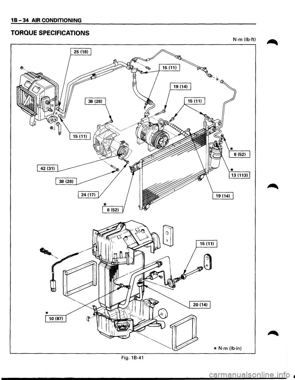
1 B-34 AIR CONDITIONING
TORQUE SPECIFICATIONS
N-m (lb·ft)
* N·m (lb·in)
Fig. 18-41
_____________ ,.
Page 92 of 1928
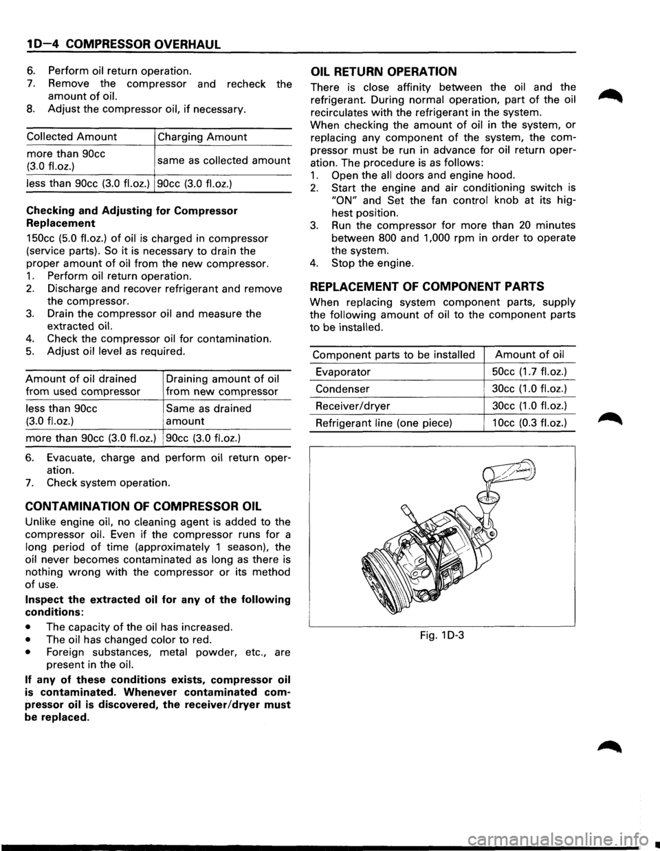
1 D-4 COMPRESSOR OVERHAUL
6. Perform oil return operation.
7. Remove the compressor and recheck the
amount of oil.
8. Adjust the compressor oil, if necessary.
Collected Amount
more than 90cc
(3.0
fl.oz.)
Charging Amount
same as collected amount
less than 90cc (3.0 fl.oz.) 90cc (3.0 fl.oz.)
Checking and Adjusting for Compressor
Replacement
150cc (5.0 fl.oz.) of oil is charged in compressor
(service parts).
So it is necessary to drain the
proper
amount of oil from the new compressor.
1. Perform oil return operation.
2. Discharge and recover refrigerant and remove
the compressor.
3. Drain the compressor oil and measure the
extracted
oil.
4. Check the compressor oil for contamination.
5. Adjust oil level as required.
Amount of oil drained
from used compressor
less than 90cc
(3.0
fl.oz.)
Draining amount of oil
from new compressor
Same as drained
amount
more than 90cc (3.0 fl.oz.) 90cc (3.0 fl.oz.)
6. Evacuate, charge and perform oil return oper
ation.
7. Check system operation.
CONTAMINATION OF COMPRESSOR OIL
Unlike engine oil, no cleaning agent is added to the
compressor
oil. Even if the compressor runs for a
long period
of time (approximately 1 season), the
oil never becomes contaminated as long
as there is
nothing
wrong with the compressor or its method
of use.
Inspect the extracted oil for any of the following
conditions:
• The capacity of the oil has increased.
• The oil has changed color to red.
• Foreign substances, metal powder, etc., are
present in the oil.
If any of these conditions exists, compressor oil
is contaminated. Whenever contaminated com
pressor
oil is discovered, the receiver/dryer must
be
replaced.
OIL RETURN OPERATION
There is close affinity between the oil and the
refrigerant. During normal operation, part
of the oil
recirculates
with the refrigerant in the system.
When checking the
amount of oil in the system, or
replacing any component of the system, the com
pressor
must be run in advance for oil return oper
ation. The procedure is as
follows:
1. Open the all doors and engine hood.
2. Start the engine and air conditioning switch is
"ON" and Set the fan control knob at its hig
hest position.
3. Run the compressor for more than 20 minutes
between
800 and 1,000 rpm in order to operate
the system.
4. Stop the engine.
REPLACEMENT OF COMPONENT PARTS
When replacing system component parts, supply
the following
amount of oil to the component parts
to be installed.
Component parts to be installed Amount of oil
Evaporator 50cc
(1.7
fl.oz.)
Condenser 30cc
(1.0 fl.oz.)
Receiver/dryer 30cc
(1.0 fl.oz.)
Refrigerant line (one piece) 1 Occ (0.3 fl. oz.)
Fig. 1 D-3
•
Page 122 of 1928
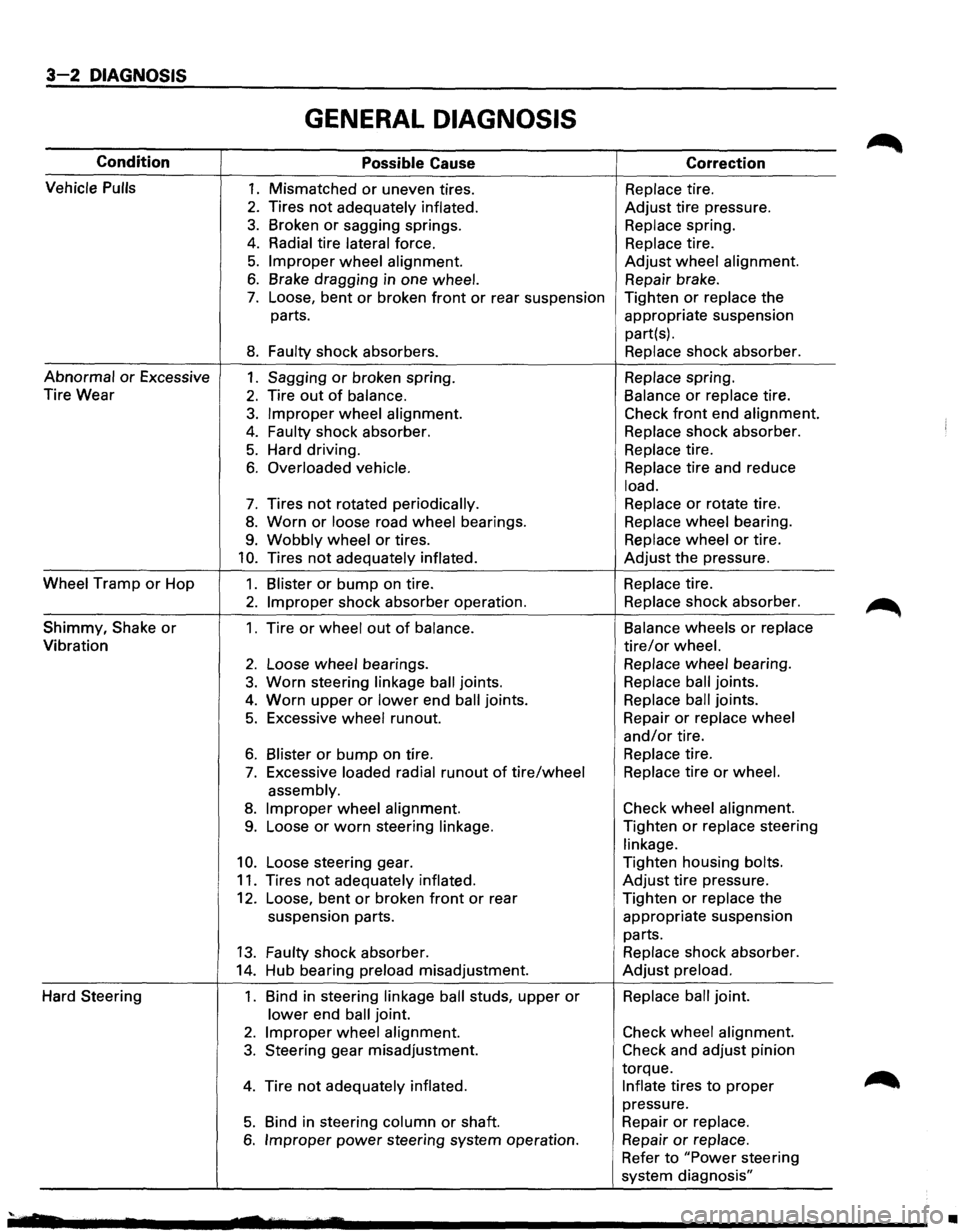
3-2 DIAGNOSIS
GENERAL DIAGNOSIS
Condition Possible Cause Correction
Vehicle
Pulls 1. Mismatched or uneven tires. Replace tire.
2. Tires not adequately inflated. Adjust tire pressure.
3. Broken or sagging springs. Replace spring.
4. Radial tire lateral force. Replace tire.
5. Improper wheel alignment. Adjust wheel alignment.
6. Brake dragging in one wheel. Repair brake.
7. Loose, bent or broken front or rear suspension Tighten or replace the
parts. appropriate suspension
part(s).
8. Faulty shock absorbers. Replace shock absorber.
Abnormal or Excessive 1. Sagging or broken spring. Replace spring.
Tire Wear
2. Tire out of balance. Balance or replace tire.
3. Improper wheel alignment. Check front end alignment.
4. Faulty shock absorber. Replace shock absorber.
5. Hard driving. Replace tire.
6. Overloaded vehicle. Replace tire
and reduce
load.
7. Tires not rotated periodically. Replace or rotate
tire.
8. Worn or loose road wheel bearings. Replace wheel bearing.
9. Wobbly wheel or tires. Replace wheel or tire.
10. Tires not adequately inflated. Adjust the pressure.
Wheel Tramp or Hop 1. Blister or bump on tire. Replace tire.
2. Improper shock absorber operation. Replace shock absorber.
Shimmy,
Shake or 1. Tire or wheel out of balance. Balance
wheels or replace
Vibration tire/or wheel.
2. Loose wheel bearings. Replace wheel bearing.
3. Worn steering linkage ball joints. Replace ball joints.
4. Worn upper or lower end ball joints. Replace ball joints.
5. Excessive wheel runout. Repair or replace
wheel
and/or tire.
6. Blister or bump on tire. Replace tire.
7. Excessive loaded radial runout of tire/wheel Replace tire or wheel.
assembly.
8. Improper wheel alignment. Check
wheel alignment.
9. Loose or worn steering linkage. Tighten or replace steering
linkage.
10. Loose steering gear. Tighten
housing bolts.
11. Tires not adequately inflated. Adjust tire pressure.
12. Loose, bent or broken front or rear Tighten or replace the
suspension parts. appropriate suspension
parts.
13. Faulty shock absorber. Replace shock absorber.
14. Hub bearing preload misadjustment. Adjust preload.
Hard Steering 1. Bind in steering linkage ball studs, upper or Replace ball joint.
lower end ball joint.
2. Improper wheel alignment. Check wheel alignment.
3. Steering gear misadjustment. Check and adjust pinion
torque.
4. Tire not adequately inflated. Inflate tires to proper
pressure.
5. Bind in steering column or shaft. Repair or replace.
6. Improper power steering
system operation. Repair or replace.
Refer to "Power steering
system diagnosis"
'· •
Page 123 of 1928
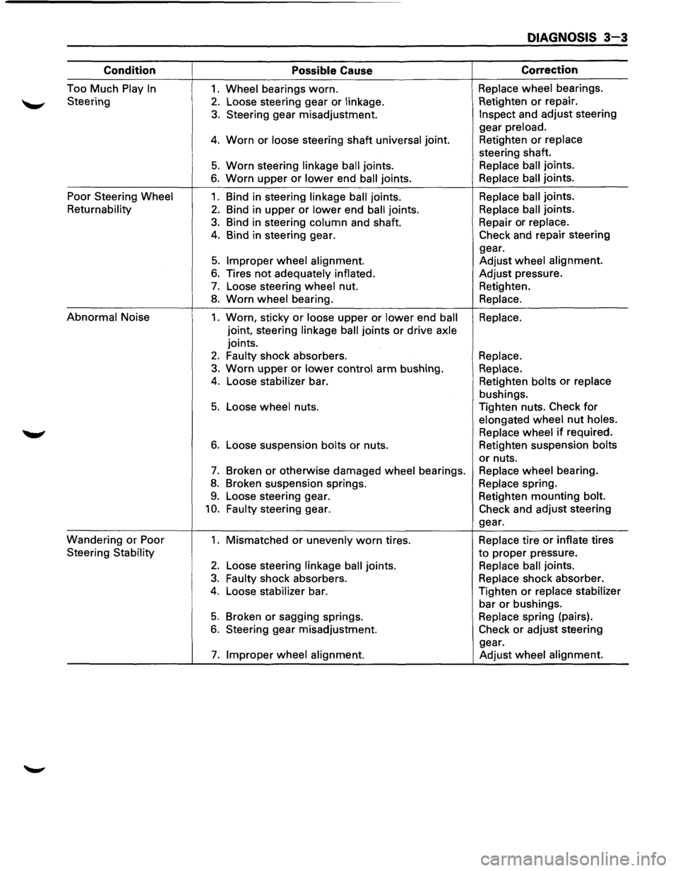
DIAGNOSIS 3-3
Condition Possible Cause Correction
Too
Much Play In 1. Wheel bearings worn. Replace wheel bearings.
Steering
2. Loose steering gear or linkage. Retighten or repair.
3. Steering
gear misadjustment. Inspect and adjust steering
gear preload.
4. Worn or loose steering shaft universal joint. Retighten or replace
steering shaft.
5. Worn steering linkage ball joints. Replace ball joints.
6. Worn upper or lower end ball joints. Replace ball joints.
Poor Steering
Wheel 1. Bind in steering linkage ball joints. Replace ball joints.
Returnability 2. Bind
in upper or lower end ball joints. Replace ball joints.
3. Bind
in steering column and shaft. Repair
or replace.
4. Bind in steering gear. Check and repair steering
gear.
5. Improper wheel alignment. Adjust wheel alignment.
6. Tires not adequately
inflated. Adjust
pressure.
7. Loose steering wheel nut. Retighten.
8. Worn wheel bearing.
Replace.
Abnormal Noise
1. Worn, sticky or loose upper or lower end ball Replace.
joint, steering linkage
ball joints or drive axle
joints.
2. Faulty shock absorbers.
Replace.
3. Worn upper or lower control arm bushing.
Replace.
4. Loose stabilizer bar. Retighten bolts or replace
bushings.
5. Loose wheel nuts. Tighten nuts. Check for
elongated wheel nut holes.
Replace
wheel if required.
6. Loose suspension bolts or nuts. Retighten suspension bolts
or nuts.
7. Broken or otherwise damaged wheel bearings. Replace wheel bearing.
8. Broken suspension springs. Replace spring.
9. Loose steering gear. Retighten mounting bolt.
10. Faulty steering gear. Check and adjust steering
gear.
Wandering
or Poor 1. Mismatched or unevenly worn tires. Replace tire or inflate tires
Steering
Stability to proper pressure.
2. Loose steering linkage ball joints. Replace ball joints.
3. Faulty shock absorbers. Replace shock absorber.
4. Loose stabilizer bar. Tighten or replace stabilizer
bar or bushings.
5. Broken or sagging springs. Replace spring (pairs).
6. Steering gear misadjustment. Check or adjust steering
gear.
7. Improper wheel alignment.
Adjust wheel alignment.
Page 124 of 1928
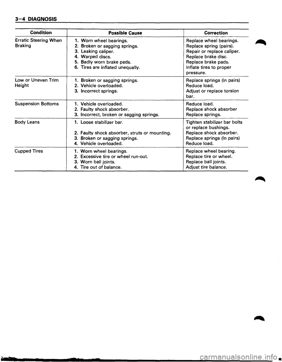
3-4 DIAGNOSIS
Condition Possible Cause Correction
Erratic Steering When 1. Worn wheel bearings. Replace wheel bearings.
Braking
2. Broken or sagging springs. Replace spring (pairs).
3. Leaking caliper. Repair or replace caliper.
4. Warped discs. Replace brake disc.
5. Badly worn brake pads. Replace brake pads.
6. Tires are inflated unequally. Inflate tires to proper
pressure.
Low or Uneven Trim
1. Broken or sagging springs. Replace springs (In pairs)
Height
2. Vehicle overloaded. Reduce load.
3. Incorrect springs. Adjust or replace torsion
bar.
Suspension Bottoms
1. Vehicle overloaded. Reduce load.
2. Faulty shock absorber. Replace shock absorber
3. Incorrect, broken or sagging springs. Replace springs.
Body Leans
1. Loose stabilizer bar. Tighten stabilizer bar bolts
or replace bushings.
2. Faulty shock
absorber, struts or mounting. Replace shock absorber.
3. Broken or sagging springs. Replace springs (In pairs)
4. Vehicle overloaded. Reduce load.
Cupped Tires 1. Worn wheel bearings. Replace wheel bearing.
2. Excessive tire or wheel run-out. Replace tire or wheel.
3. Worn ball joints. Replace ball joints.
4. Tire out of balance. Adjust tire balance.
•
Page 125 of 1928
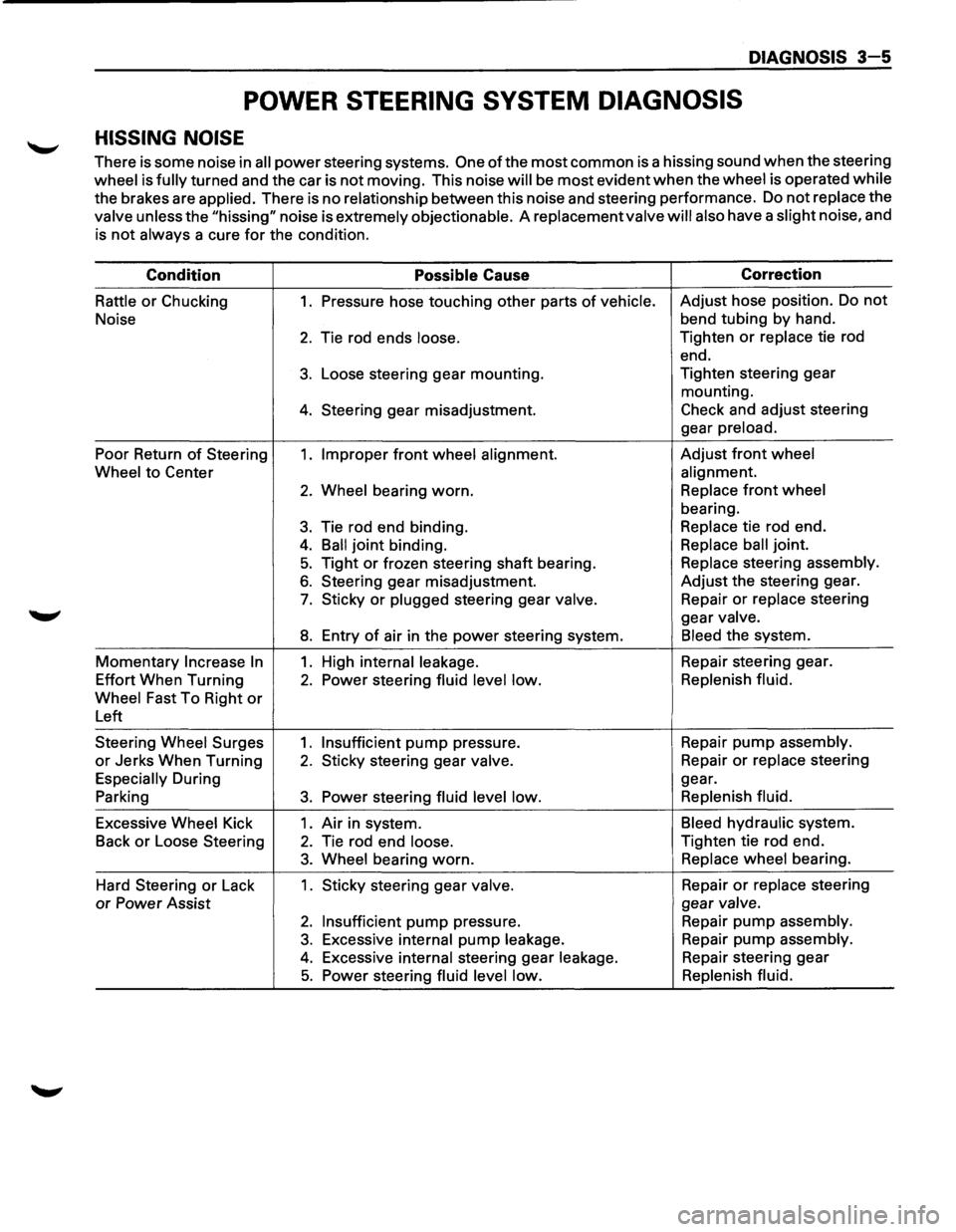
DIAGNOSIS 3-5
POWER STEERING SYSTEM DIAGNOSIS
HISSING NOISE
There is some noise in all power steering systems. One of the most common is a hissing sound when the steering
wheel is fully turned and the car is not moving. This noise will be most evident when the wheel is operated while
the brakes are applied. There is no relationship between this noise and steering performance. Do not replace the
valve unless the "hissing" noise is extremely objectionable. A replacement valve will also have a slight noise, and
is
not always a cure for the condition.
Condition
Possible Cause Correction
Rattle or Chucking 1. Pressure
hose touching other parts of vehicle. Adjust hose position. Do not
Noise bend
tubing by hand.
2. Tie rod ends loose. Tighten or replace tie rod
end.
3. Loose steering gear mounting. Tighten
steering gear
mounting.
4. Steering gear misadjustment. Check and adjust steering
gear
preload.
Poor Return of Steering 1. Improper front wheel alignment. Adjust front wheel
Wheel
to Center alignment.
2. Wheel bearing worn. Replace front wheel
bearing.
3. Tie rod end binding. Replace tie rod end.
4. Ball joint binding. Replace ball joint.
5. Tight or frozen steering shaft bearing. Replace steering assembly.
6. Steering gear misadjustment. Adjust the steering gear.
7. Sticky or plugged steering gear valve. Repair or replace steering
gear
valve.
8. Entry of air in the power steering system. Bleed the system.
Momentary Increase In 1. High internal leakage. Repair steering gear.
Effort When Turning
2. Power steering fluid level low. Replenish
fluid.
Wheel
Fast To Right or
Left
Steering
Wheel Surges 1. Insufficient pump pressure. Repair pump assembly.
or Jerks
When Turning 2. Sticky steering gear valve. Repair or replace steering
Especially During gear.
Parking
3. Power steering fluid level low. Replenish
fluid.
Excessive Wheel Kick 1. Air in system. Bleed hydraulic system.
Back
or Loose Steering 2. Tie rod end loose. Tighten tie rod end.
3. Wheel bearing worn. Replace wheel bearing.
Hard Steering
or Lack 1. Sticky steering gear valve. Repair or replace steering
or Power Assist gear valve.
2. Insufficient pump pressure.
Repair pump assembly.
3. Excessive internal pump leakage. Repair
pump assembly.
4. Excessive internal steering gear leakage. Repair steering gear
5. Power steering fluid level low. Replenish
fluid.
Page 126 of 1928
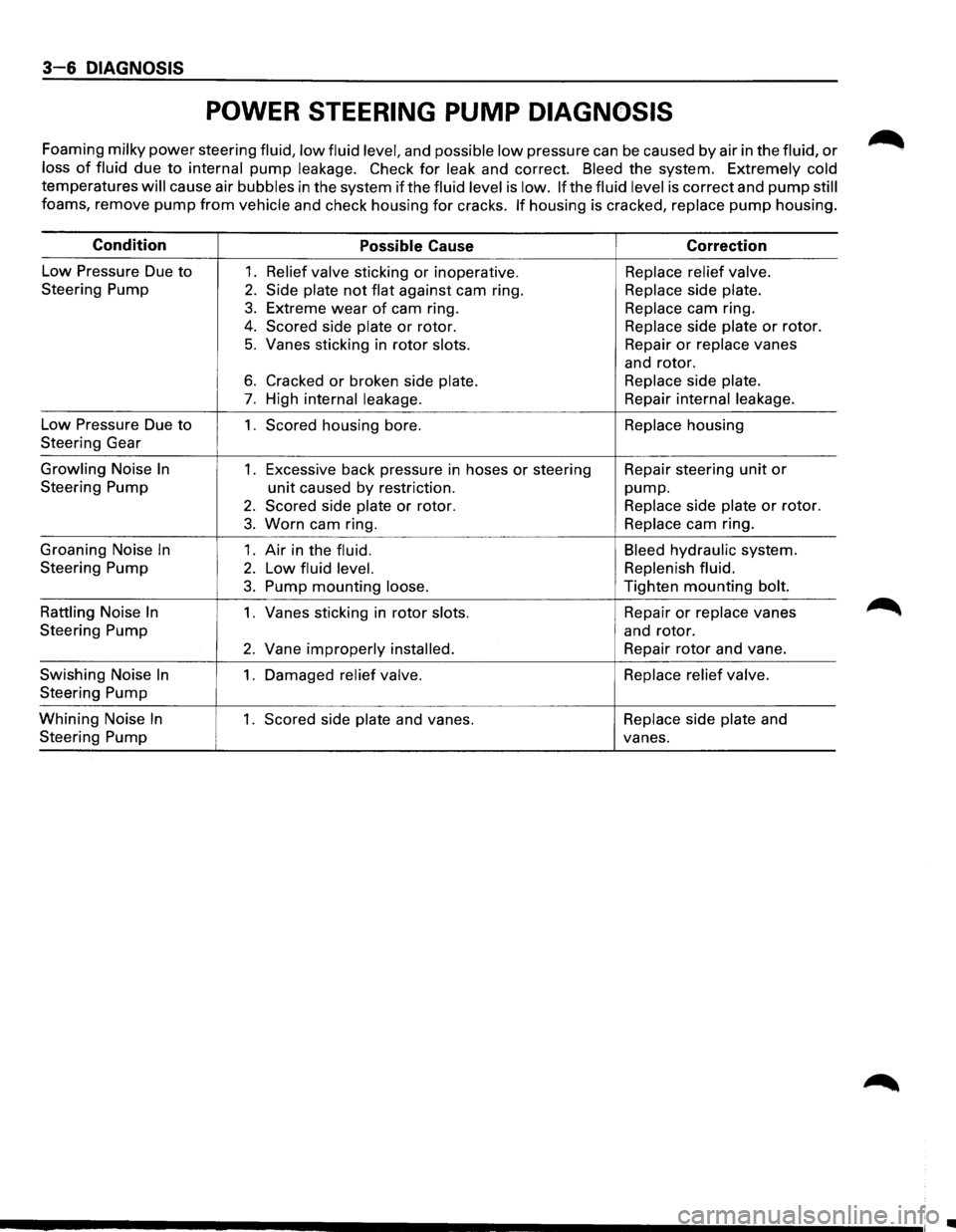
3-6 DIAGNOSIS
POWER STEERING PUMP DIAGNOSIS
Foaming milky power steering fluid, low fluid level, and possible low pressure can be caused by air in the fluid, or
loss of fluid due to internal pump leakage. Check for leak and correct. Bleed the system. Extremely cold
temperatures
will cause air bubbles in the system if the fluid level is low. If the fluid level is correct and pump still
foams, remove pump from vehicle and check housing for cracks. If housing is cracked, replace pump housing.
Condition
Possible Cause Correction
Low Pressure
Due to 1. Relief valve sticking or inoperative. Replace relief valve.
Steering Pump
2. Side plate not flat against cam ring. Replace side plate.
3. Extreme wear of cam ring. Replace cam ring.
4. Scored side plate or rotor. Replace
side plate or rotor.
5. Vanes sticking in rotor slots. Repair or replace vanes
and rotor.
6. Cracked or broken side plate. Replace side plate.
7. High internal leakage. Repair internal leakage.
Low Pressure Due to 1. Scored housing bore. Replace housing
Steering Gear
Growling Noise
In 1. Excessive back pressure in hoses or steering Repair
steering unit or
Steering Pump
unit caused by restriction. pump.
2. Scored side plate or rotor. Replace
side plate or rotor.
3. Worn cam ring. Replace
cam ring.
Groaning Noise
In 1. Air in the fluid. Bleed hydraulic system.
Steering Pump
2. Low fluid level. Replenish fluid.
3. Pump mounting loose. Tighten
mounting bolt.
Rattling Noise
In 1. Vanes sticking in rotor slots. Repair or replace
vanes
Steering Pump and rotor.
2. Vane improperly installed. Repair rotor and vane.
Swishing Noise
In 1. Damaged relief valve. Replace
relief valve.
Steering Pump
Whining Noise
In 1. Scored side plate and vanes. Replace
side plate and
Steering Pump
vanes.
•
Page 127 of 1928
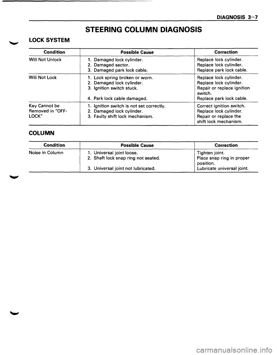
LOCK SYSTEM
Condition
Will Not Unlock
Will Not Lock
Key
Cannot be
Removed in "OFF-
LOCK"
COLUMN
Condition
Noise in Column
DIAGNOSIS 3-7
STEERING COLUMN DIAGNOSIS
Possible Cause
1. Damaged lock cylinder.
2. Damaged sector.
3. Damaged park lock cable.
1. Lock spring broken or worn.
2. Damaged lock cylinder.
3. Ignition switch stuck.
4. Park lock cable damaged.
1. Ignition switch is not set correctly.
2. Damaged lock cylinder.
3. Faulty shift lock mechanism.
Possible Cause
1. Universal joint loose.
2. Shaft lock snap ring not seated.
3. Universal joint not lubricated.
Correction
Replace lock cylinder.
Replace lock cylinder.
Replace park lock cable.
Replace lock cylinder.
Replace lock cylinder.
Repair
or replace ignition
switch.
Replace park lock cable.
Correct ignition switch.
Replace lock cylinder.
Repair
or replace the
shift lock mechanism.
Correction
Tighten joint.
Place snap ring in proper
position.
Lubricate universal joint.
Page 128 of 1928
3-8 DIAGNOSIS
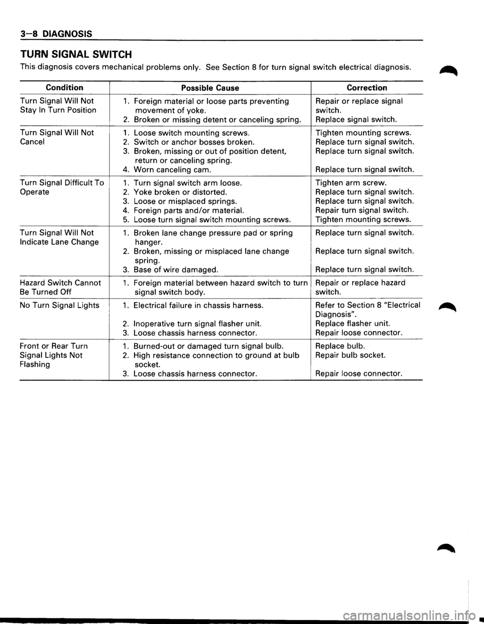
TURN SIGNAL SWITCH
This diagnosis covers mechanical problems only. See Section 8 for turn signal switch electrical diagnosis. ~
Condition Possible Cause Correction
Turn Signal
Will Not 1. Foreign material or loose parts preventing Repair or replace
signal
Stay
In Turn Position movement of yoke. switch.
2. Broken or missing detent or canceling spring. Replace
signal switch.
Turn Signal
Will Not 1. Loose switch mounting screws. Tighten mounting screws.
Cancel
2. Switch or anchor bosses broken. Replace
turn signal switch.
3. Broken, missing or out of position detent, Replace
turn signal switch.
return
or canceling spring.
4. Worn canceling cam. Replace
turn signal switch.
Turn Signal Difficult To
1. Turn signal switch arm loose. Tighten
arm screw.
Operate
2. Yoke broken or distorted. Replace
turn signal switch.
3. Loose or misplaced springs. Replace
turn signal switch.
4. Foreign parts and/or material. Repair
turn signal switch.
5. Loose turn signal switch mounting screws. Tighten mounting screws.
Turn Signal Will Not
1 . Broken lane change pressure pad or spring Replace
turn signal switch.
Indicate Lane Change
hanger.
2. Broken, missing or misplaced lane change Replace
turn signal switch.
spring.
3. Base of wire damaged. Replace
turn signal switch.
Hazard Switch Cannot
1. Foreign material between hazard switch to turn Repair
or replace hazard
Be Turned Off
signal switch body. switch.
No Turn Signal Lights
1. Electrical failure in chassis harness. Refer to Section
8 "Electrical
Diagnosis".
2. Inoperative turn signal flasher unit. Replace
flasher unit.
3. Loose chassis harness connector. Repair
loose connector.
Front or Rear Turn
1. Burned-out or damaged turn signal bulb. Replace
bulb.
Signal Lights
Not 2. High resistance connection to ground at bulb Repair
bulb socket.
Flashing socket.
3. Loose chassis harness connector. Repair
loose connector.
•
Page 139 of 1928
POWER STEERING GEAR AND PUMP 381 -1
SECTION 381
POWER STEERING GEAR AND PUMP
w CAUTION:
When fasteners are removed, always reinstall them at the same location from which they were removed.
If a fastener needs to be replaced, use the correct part number fastener for that application. If the correct
part
number fastener is not available, a fastener of equal size and strength (or stronger) may be used.
Fasteners
that are not reused, and those requiring thread locking compound, will be called out. The correct
torque value must be used when installing fasteners that require it. If the above conditions are not
followed, parts or system damage could result.
CONTENTS
General Description ............................ 3B1- 1
Steering Wheel Free Play Adjustment .... 3B1-5
Power Steering
Gear........................ 3B1-1
Steering Gear ................................ 3B1-6
Hydraulic Pump .............................. 3B1- 1
Power Steering Pump ...................... 3B1-8
Pressure Switch
............................. 3B1-1
Unit Repair ...................................... 3B1- 9
Power Steering System Test
................. 3B1-3
Steering Gear ................................ 3B1-9
On-Vehicle Service ............................. 3B1- 4
Power Steering Pump ...................... 3B1-14
Maintenance
................................. 3B1- 4
Main Data and Specifications ................ 3B1-17
Fluid Level .................................... 3B1- 4 General Specifications ...................... 3B1-17
Bleeding The Power Steering System .... 3B1-4
Torque Specifications ....................... 3B1-17
Bleeding Procedure ......................... 3B1-4 Special Tools.................................... 3B1-18
Flushing The Power Steering System .... 3B1-4
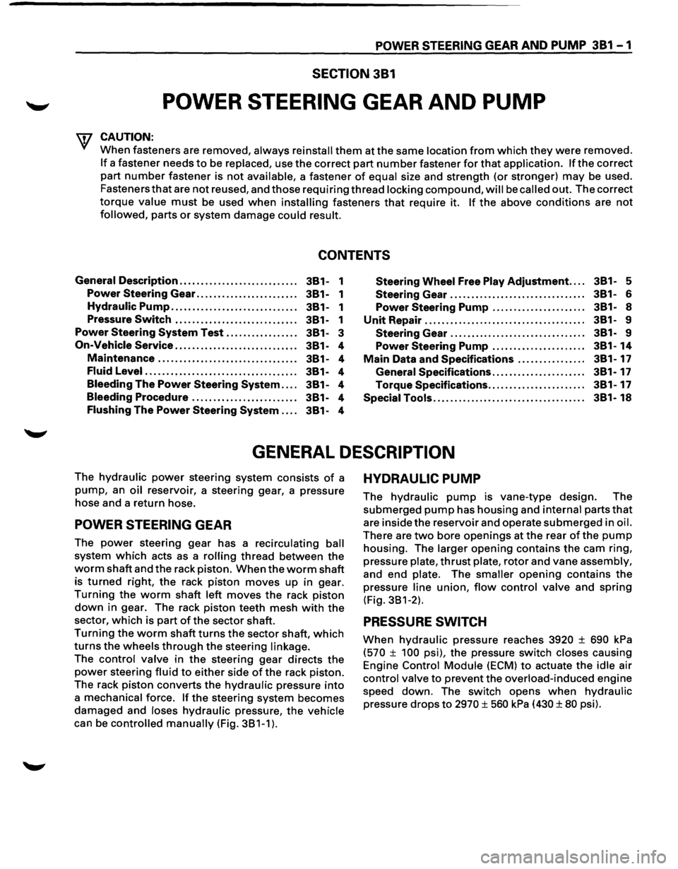
GENERAL DESCRIPTION
The hydraulic power steering system consists of a
pump, an oil reservoir, a steering gear, a pressure
hose and a return hose.
POWER STEERING GEAR
The power steering gear has a recirculating ball
system which acts as a rolling thread between the
worm shaft and the rack piston. When the worm shaft
is
turned right, the rack piston moves up in gear.
Turning the worm shaft left moves the rack piston
down in gear. The rack piston teeth mesh with the
sector, which is part ofthe sector shaft.
Turning the worm shaft turns the sector shaft, which
turns the wheels through the steering linkage.
The control valve in the steering gear directs the
power steering fluid to either side of the rack piston.
The rack
piston converts the hydraulic pressure into
a mechanical force. If the steering system becomes
damaged and loses hydraulic pressure, the vehicle
can be controlled manually (Fig. 381-1).
HYDRAULIC PUMP
The hydraulic pump is vane-type design. The
submerged pump has housing and internal parts that
are inside the reservoir and operate submerged in oil.
There are two bore openings at the rear of the pump
housing. The larger opening contains the cam ring,
pressure
plate, thrust plate, rotor and vane assembly,
and end plate. The smaller opening contains the
pressure
line union, flow control valve and spring
(Fig. 381-2).
PRESSURE SWITCH
When hydraulic pressure reaches 3920 ± 690 kPa
(570 ± 100 psi), the pressure switch closes causing
Engine
Control Module (ECM) to actuate the idle air
control valve to prevent the overload-induced engine
speed down. The switch opens
when hydraulic
pressure drops to 2970 ± 560 kPa (430 ± 80 psi).