heater ISUZU TROOPER 1995 Owner's Guide
[x] Cancel search | Manufacturer: ISUZU, Model Year: 1995, Model line: TROOPER, Model: ISUZU TROOPER 1995Pages: 1928
Page 606 of 1928
~:· T·, ·.}:
6A1-48 ENGINE (V6 3.2L DOHC AND SOHC)
33. Cylinder head cover
• Remove 11 fixing bolts, then the cylinder head
cover.
34. Power steering pump bracket
• Disconnect ground cable from bracket.
35.
• Remove five fixing bolts, then the bracket.
Exhaust front pipe
36.
37. Level gage fixing bolt
• Remove from cylinder head.
Cylinder head
1••1 INSTALLATION
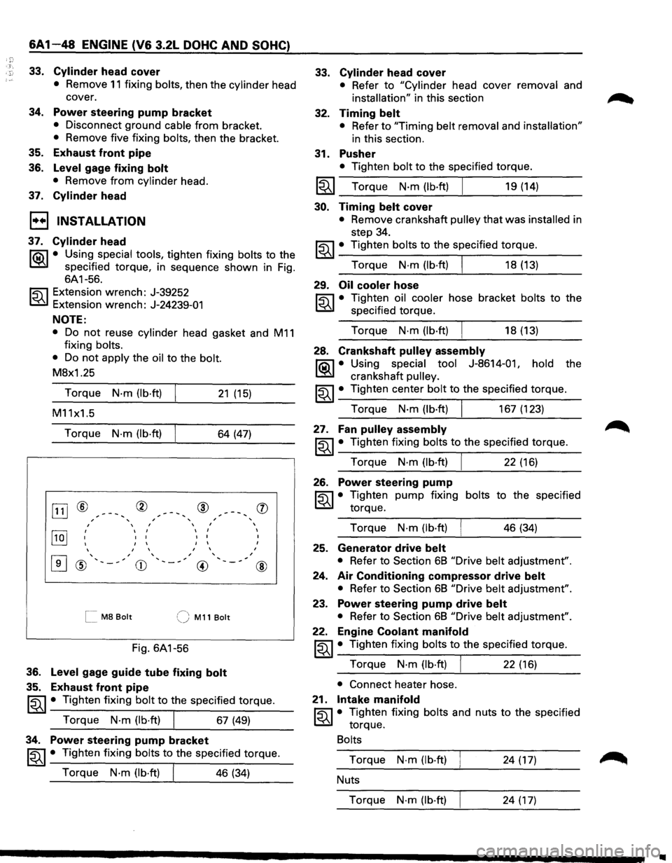
37. Cylinder head
li0\1 • Using special tools, tighten fixing bolts to the
~ specified torque, in sequence shown in Fig.
6A1-56.
~ Extension wrench: J-39252
t:6.l Extension wrench: J-24239-01
NOTE:
• Do not reuse cylinder head gasket and M11
fixing bolts.
•
Do not apply the oil to the bolt.
M8x1.25
Torque
N·m (lb·ft) 21 (15)
M11x1.5
Torque
N·m (lb·ft) 64 (47)
OJ] ® ® ® , ' ' ,
, I , ,
[IQJ ' I I
I I
I I I
I I
I I I
I I
,
[I] ' , , ' @ ' ,
CD ' , , __
@
[[ M8 Bolt (J M11 Bolt
Fig.
6A1-56
36. Level gage guide tube fixing bolt
35. Exhaust front pipe
'
,
(])
I
I
I
,
@
~~~ • Tighten fixing bolt to the specified torque.
Torque
N·m (lb·ft) I 67 (49)
34. Power steering pump bracket
~~~ • Tighten fixing bolts to the specified torque.
Torque
N·m (lb·ft) I 46 (34)
33.
32.
31.
Cylinder head cover
• Refer to "Cylinder head cover removal and
installation" in this section
Timing belt
• Refer to "Timing belt removal and installation"
in this section.
Pusher
• Tighten bolt to the specified torque.
I~I __ T_o_r~qu_e __ N_·_m~(lb_·ft_)~ ______ 1_9_(1_4_) ____ _
30. Timing belt cover
• Remove crankshaft pulley that was installed in
step 34.
~~~· Tighten bolts to the specified torque.
Torque
N·m (lb·ft) I 18 (13)
29. Oil cooler hose
~ • Tighten oil cooler hose bracket bolts to the
t:6.l specified torque.
Torque
N·m (lb·ft) I 18 (13)
28. Crankshaft pulley assembly
li0\1 • Using special tool J-8614-011 hold the
~ crankshaft pulley.
~~~ • Tighten center bolt to the specified torque.
Torque
N·m (lb·ft) I 167 (123)
27. Fan pulley assembly
~~~· Tighten fixing bolts to the specified torque.
Torque
N·m (lb·ft) I 22 (16)
26. Power steering pump
~ • Tighten pump fixing bolts to the specified
t:6.l torque.
Torque
N·m (lb·ft) I 46 (34)
25. Generator drive belt
• Refer to Section 68 "Drive belt adjustment".
24.
Air Conditioning compressor drive belt
• Refer to Section 68 "Drive belt adjustment".
23. Power steering pump drive belt
• Refer to Section 68 "Drive belt adjustment".
22. Engine Coolant manifold
~~~· Tighten fixing bolts to the specified torque.
Torque
N·m (lb·ft) I 22 (16)
• Connect heater hose.
21.
Intake manifold
~ • Tighten fixing bolts and nuts to the specified
t:6.l torque.
Bolts
Torque N·m (lb·ft) 24 (17)
Nuts
Torque
N·m (lb·ft) 24 (17)
..
Page 620 of 1928
'.n
6A1-62 ENGINE (V6 3.2L DOHC AND SOHC)
E) REMOVAL
Preparation: • Disconnect battery ground cable.
• Remove engine hood.
In order to return the hood to the
original position exactly, make
alignment on the hood and hinges
before
removal.
•
Drain radiator coolant.
1. Accelerator cable
• Disconnect from throttle valve and common
chamber.
2. Ventilation hose
3.
Air hose
4. Air cleaner assembly
5. Canister vacuum hose
6. Vacuum booster hose
7. Engine harness connectors
• Disconnect three connectors on canister side.
8. Battery ground cables
• Disconnect two black and white connector
clips
from the power steering pump bracket.
9. Ground cables
• Disconnect two terminals connected to the
battery support and the
front right frame.
1 0. Bonding cable connector
• Disconnect connector on the left side dash
panel.
11. Bonding cable terminal
• Disconnect terminal on the back of left bank.
12. Starter harness connector
• Disconnect from starter.
13. Radiator
• Disconnect upper and lower hoses from the
engine.
• Disconnect coolant reserve tank hose from
radiator.
• Disconnect ATF hose from the pipe. (A/T)
• Remove radiator lower hose clip from the hose
bracket.
• Remove radiator lower fan shroud.
• Remove radiator.
14. Power steering pump drive belt
15. Power steering pump
• Remove two bolts on the bracket, and place the
pump along with piping on the body side.
16. Air Conditioning compressor drive belt
17. Air Conditioning compressor
• Remove fixing bolts and shift aside the
compressor
with piping attached.
18. Heater hoses
• Disconnect two hoses from the engine.
19. ATF pipes
• Disconnect two pipes from right side engine
mount.
20. Transmission assembly
• See "Transmission Removal and Installation"
in Section 7.
21. Left side engine mount
• Support the engine.
• Remove two fixing bolts from engine mount on
chassis side.
22. Right side engine mount
• Remove two fixing bolts from engine mount on
chassis side.
23. Engine assembly
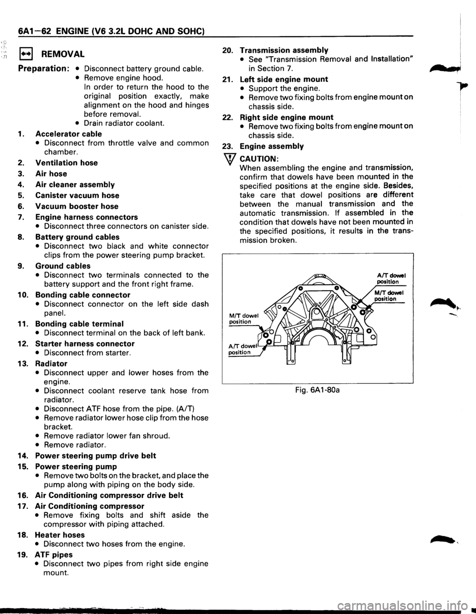
w CAUTION:
When assembling the engine and transmission,
confirm
that dowels have been mounted in the
specified positions at the engine side. Besides,
take care
that dowel positions are different
between the manual transmission and the
automatic transmission.
If assembled in the
condition that dowels have not been mounted in
the specified positions,
it results in the trans
mission broken.
M/Tdowel position
AIT doweiY~--r..ri~-' position
Fig. 6A1-80a
n t b,
•
Page 632 of 1928
68 - 4 ENGINE COOLING
ON-VEHICLE SERVICE
DRAINING AND REFILLING COOLING
SYSTEM
Before draining the cooling system, inspect the sys
tem and perform any necessary service to ensure that
it is clean, does not leak and is in proper working
order. The Engine Coolant (EC) level should be be
tween the "MIN" and "MAX" lines of reserve tank
when the engine is cold. If low, check for leakage and
add
EC up to the "MAX" line. There should not be any
excessive deposit of rust or scales around the radiator
cap
or radiator filler hole, and the EC should also be
free
from oil. Replace the EC if excessively dirty.
1. Completely drain the cooling system by opening
the drain petcock at the bottom of the radiator.
2. Remove the radiator cap.
W WARNING
To avoid the danger of being burned, do not
remove the cap while the engine and radiator
are still hot. Scalding fluid and steam can be
blown out under pressure.
3. Disconnect all hoses from the EC reserve tank.
Scrub and clean the inside of the reserve tank with
soap and water. Flush it well with clean water,
then drain it. Install the reserve tank and hoses.
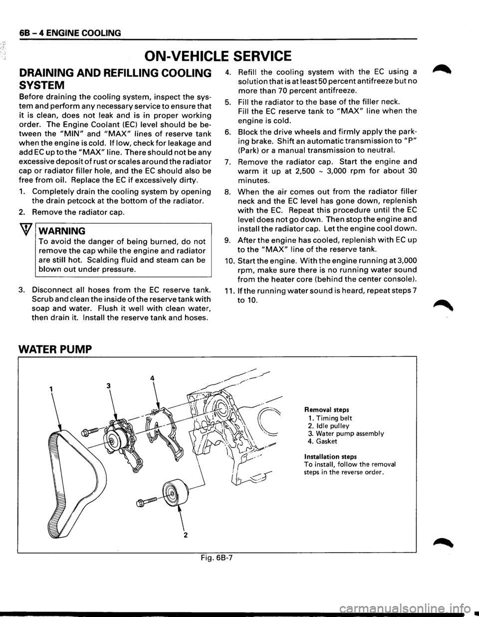
WATER PUMP
3
j
2
4. Refill the cooling system with the EC using a
solution that is at least 50 percent antifreeze but no
more than 70 percent antifreeze.
5. Fill the radiator to the base of the filler neck.
Fill the EC reserve tank to "MAX" line when the
engine is cold.
6. Block the drive wheels and firmly apply the park
ing brake.
Shift an automatic transmission to "P"
(Park) or a manual transmission to neutral.
7. Remove the radiator cap. Start the engine and
warm it up at 2,500 -3,000 rpm for about 30
minutes.
8. When the air comes out from the radiator filler
neck and the EC level has gone down, replenish
with the EC. Repeat this procedure until the EC
level does not go down. Then stop the engine and
install the radiator cap. Let the engine cool down.
9. After the engine has cooled, replenish with EC up
to the "MAX" line of the reserve tank.
10. Start the engine. With the engine running at 3,000
rpm, make sure there is no running water sound
from the heater core (behind the center console).
11. If the running water sound is heard, repeat steps 7
to 10.
Removal steps
1. Timing
belt 2. Idle pulley 3. Water pump assembly
4. Gasket
Installation steps To install, follow the removal steps in the reverse order.
Fig. 6B-7
•
Page 637 of 1928
E!) INSTALLATION
6. Radiator assembly
• Install cushion rubbers on both sides of radia
tor bottom.
• Install radiator assembly with hose, taking
care
not to damage the radiator core with a fan
blade.
5. Bracket
• Support the radiator uppertankwith the bracket
and secure the radiator.
4. Reserve tank hose
3. Fan guide, lower
2. Radiator hose
• Connect inlet hose and outlet hose to the
engine.
1. Oil cooler hose (A/T)
• Connect oil cooler hose for automatic trans-
mission.
• Connect battery ground cable.
• Pour engine coolant.
• Pour engine coolant up to filler neck of radia
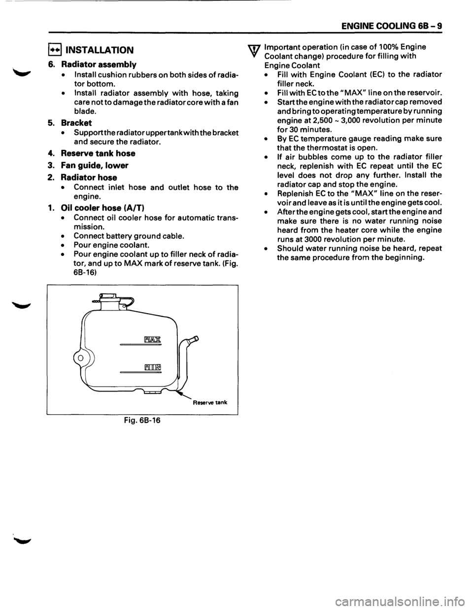
tor, and up to MAX mark of reserve tank. (Fig.
68-16)
Reserve tank
Fig. 68-16
ENGINE COOLING 68-9
U7 Important operation (in case of 100% Engine
V Coolant change) procedure for filling with
Engine Coolant
• Fill
with Engine Coolant (EC) to the radiator
filler neck.
• Fill with EC to the "MAX" line on the reservoir.
• Start the engine with the radiator cap removed
and bring
to operating temperature by running
engine at
2,500-3,000 revolution per minute
for 30 minutes.
• By EC temperature gauge reading make sure
that the thermostat is open.
• If air bubbles come up to the radiator filler
neck, replenish with EC repeat until the EC
level does not drop any further. Install the
radiator cap and stop the engine.
• Replenish EC to the "MAX" line on the reser
voir and leave as it is until the engine gets cool.
• After the engine gets cool, start the engine and
make sure there is no
water running noise
heard
from the heater core while the engine
runs
at 3000 revolution per minute.
• Should water running noise be heard, repeat
the same procedure from the beginning.
Page 720 of 1928
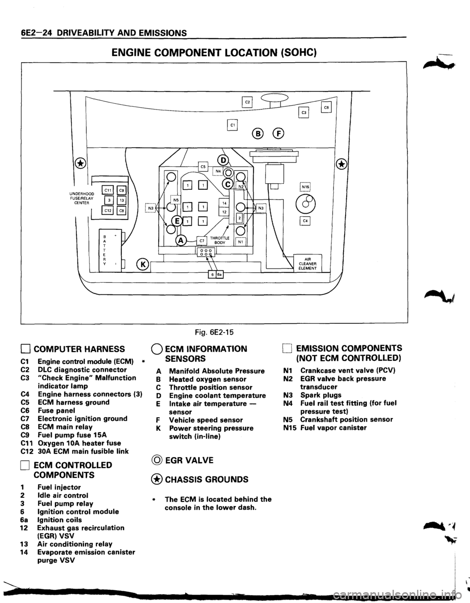
6E2-24 DRIVEABILITY AND EMISSIONS
ENGINE COMPONENT LOCATION (SOHC)
UNDERHOOD
FUSE/RELAY
CENTER
8 A
T
T
E
R y
0 COMPUTER HARNESS
C1 Engine control module (ECM) *
C2 DLC diagnostic connector
C3 "Check Engine" Malfunction
indicator lamp
C4 Engine harness connectors (3)
C5 ECM harness ground
C6 Fuse panel
C7 Electronic ignition ground
CS ECM main relay
C9 Fuel pump fuse 15A
C11 Oxygen 1 OA heater fuse
C12 30A ECM main fusible link
0 ECM CONTROLLED
COMPONENTS
1 Fuel injector
2 Idle air control
3 Fuel pump relay
6 Ignition control module
6a Ignition coils
12 Exhaust gas recirculation
(EGR) VSV
13 Air conditioning relay
14 Evaporate emission canister
purge VSV
Fig. 6E2-15
Q ECM INFORMATION
SENSORS
®
A Manifold Absolute Pressure
B Heated oxygen sensor
C Throttle position sensor
D Engine
coolant temperature
E Intake air temperature -
sensor
F Vehicle speed sensor
K Power steering pressure
switch (in-line)
@ EGRVALVE
@CHASSIS GROUNDS
* The ECM is located behind the
console in the lower dash.
®
[::::J EMISSION COMPONENTS
(NOT
ECM CONTROLLED)
N1 Crankcase vent valve (PCV)
N2 EGR valve back pressure
transducer
N3 Spark plugs
N4 Fuel rail test fitting (for fuel
pressure test)
N5 Crankshaft position sensor
N15 Fuel vapor canister
Page 721 of 1928
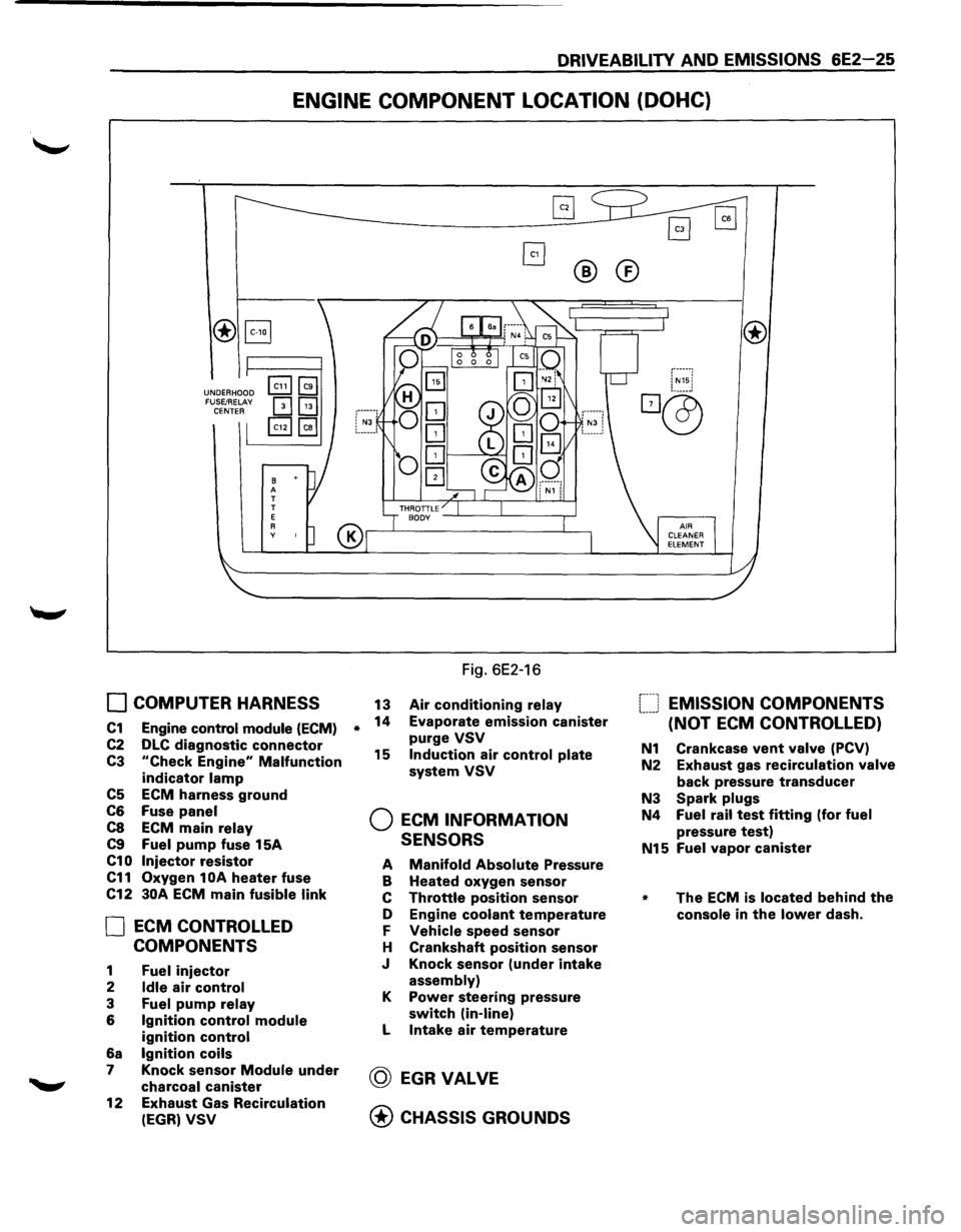
DRIVEABILITY AND EMISSIONS 6E2-25
ENGINE COMPONENT LOCATION (DOHC)
®B
UNDERHOOD FUSE/RELAY CENTER
B A T
T
E
A y
0 COMPUTER HARNESS
C1 Engine control module (ECM)
C2 DLC diagnostic connector
C3 "Check Engine" Malfunction
indicator lamp
C5 ECM harness ground
C6 Fuse panel
C8 ECM main relay
C9 Fuel pump fuse 15A
C10 Injector resistor
C11 Oxygen 1 OA heater fuse
C12
30A ECM main fusible link
0 ECM CONTROLLED
COMPONENTS
1 Fuel injector
2 Idle air control
3 Fuel pump relay
6 Ignition control module
ignition control
6a Ignition coils
7 Knock sensor Module under
charcoal canister
12
Exhaust Gas Recirculation
(EGR) VSV
*
®®
Fig. 6E2-16
13 Air conditioning relay
14 Evaporate emission canister
purge VSV
15 Induction air control plate
system VSV
Q ECM INFORMATION
SENSORS
A Manifold Absolute Pressure
B Heated oxygen sensor
c Throttle position sensor
D Engine
coolant temperature
F Vehicle speed sensor
H Crankshaft
position sensor
J Knock sensor
(under intake
assembly)
K Power steering pressure
switch (in-line)
L Intake air temperature
@ EGRVALVE
@ CHASSIS GROUNDS
f----1 EMISSION COMPONENTS !.-----' (NOT ECM CONTROLLED)
N1 Crankcase vent valve (PCV)
N2 Exhaust gas
recirculation valve
back pressure transducer
N3 Spark plugs
N4 Fuel rail test fitting (for fuel
pressure test)
N15 Fuel vapor canister
* The ECM is located behind the
console in the lower dash.
Page 723 of 1928
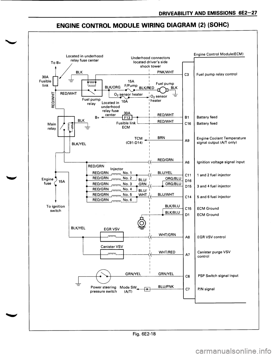
DRIVEABILITY AND EMISSIONS 6E2-27
ENGINE CONTROL MODULE WIRING DIAGRAM (2) (SOHC)
Located in underhood Engine Control
Module(ECM) Underhood connectors
To B+ relay fuse center located driver's side
/r BLK r----------s-ho-c-1-:-t-ow_:_::...:~.:..:K!Wc..:...:..:H:...:T.:..__---I C3 Fuel pump relay control
30A
Fusible
link
15A I F/P 1 Fuel pump BLK/ORG ~~
02 sensor heater 1 1 0 -2 sensor -10A 1 heater Fuel pump
BLK/YEL
relay Located in underhood relay fuse
center
B+ ------1
I
REO/WHT t---.-----t--:..:.::::..=.!...:...:..:..:...:_.:..._--1 B 1 Battery feed
REO/WHT
'-----t--..:.:..::-=:!....:c.:.:...:.-=-------1 C16 Battery feed
TCM BRN (C91-014) -_.:..._--=..:..:..:...:----1 A9 Engine Coolant Temperature signal output (A/T only)
L----~-----------~~-.:..:R.:::EO~/~G~R~N_:_--IA6 Ignition
voltage signal input
Engine
fuse 15A
To
ignition switch BLK/YEL
=
REO/GRN
REO/GRN
REO/GRN
REO/GRN
REO/GRN
REO/GRN
REO/GRN
ORG/BLU 016
ORG/BLU 015
L:...:..::..:-=---.....-:..:.:....:...!._{ L_B::..:L:..:U:c..IW:..:..:...:.HT_:__--l c " 14
BLK/BLU C15
,--.----<.._.:::B.:::LKI=B.::.LU=---1 01
GRN/YEL GRN/YEL
~--~~~~--~~~~--~C6
Power steering Mode SW--+*-f--=-8=-LU~/.:..P.:..:N~K:___---l pressure switch (A/T) C7
Fig. 6E2-18
1 and 2 fuel injector
3 and 4 fuel injector
5 and 6 fuel injector
ECM Ground
ECM Ground
EGR VSV control
Canister purge VSV
control
PSP Switch signal input
P/N signal
Page 726 of 1928
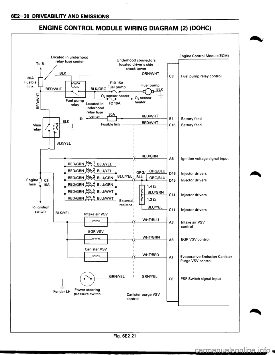
6E2-30 DRIVEABILITY AND EMISSIONS
ENGINE CONTROL MODULE WIRING DIAGRAM (2) (DOHC)
Located in underhood Engine Control Module(ECM)
T B relay
fuse center Underhood connectors
o + located
driver's side r--. / shock tower
/ I BLK.---+-I_: ~==-----------+-: __ O_R_N...:./W_H_T_--1 C3 Fuel pump relay control
Fusible
= tti F10 15A 1
30A
I' k I 1 Fuel pump In REO/WHT BLK/ORG Fu:.._pu~
~ ~-T 02 sensor heater :
0 _ ~ I ~ 2 sensor -<. Fuel pump ~ lh @ relay Located in F2 10A 1 eater
a:'---underhood
relay fuse I
BLK 30A
1 B+ _..;c:..::ec:..:n-=.:te:.:..r_-1 REO/WHT B1 Battery
feed
Fusible link
lL---,--1 _ _:.:R:.=E-==O'-'fW:..:..:....:H-=-T---i C16 Battery feed Main relay
BLK/YEL I
I
I
I
I
I
I
L---~--------------<)1 REO/GRN ,1, A6
Engine ') CB fuse 15A
To ignition switch
REO/GRN No. 1
BLU/YEL I
REO/GRN No.2 BLU/YEL : ORG/ ORG/BLU 016
015
REO/GRN No.3 BLU/GRN
BLU/YEL }1 BLU l ORG/BLU L....::-=-=.:...=.:._.._ __ -<
REO/GRN No.4
BLU/GRN \'
REO/GRN No. 5
BLU/WHT
REO/GRN No. 6 BLU/WHT I
I
External1 resistor 1 I
1.4 n
t-+--B_L-'U/_G_R_N--1 C
14
1.3Q
'---=B:..::L:..::U_:_IY;_:E:.:L~ C 11 BLK/YEL Intake air VSV I
I
l
I I t.__-1~-----< t--...:...W:..:.H.:....:.T.:...::/B:..::Lc::.U_-1 A
3
I
I
I
EGRVSV
'---111 ____ -<' (-_...:...W.:....:.H.:....:.T.:...c/G=-R_N_-1 AB
Canister VSV 1
I 1
/ WHT/REO I '---1~-----<,f--,--"------1 A7 ~------~ I I I I
~r---G~RN~/Y~E_L __ 1 __ G~R_N...:.!Y_EL_~ C 6
Fender
LH Power steering
pressure switch Canister purge VSV
control
Fig. 6E2-21
Ignition voltage signal input
Injector drivers
Injector drivers
Injector drivers
Injector drivers
Intake air VSV
control
EGR VSV control
Evaporative Emission Canister
Purge VSV control
PSP Switch signal input
1111
Page 744 of 1928
6E2-48 DRIVEABILITY AND EMISSIONS
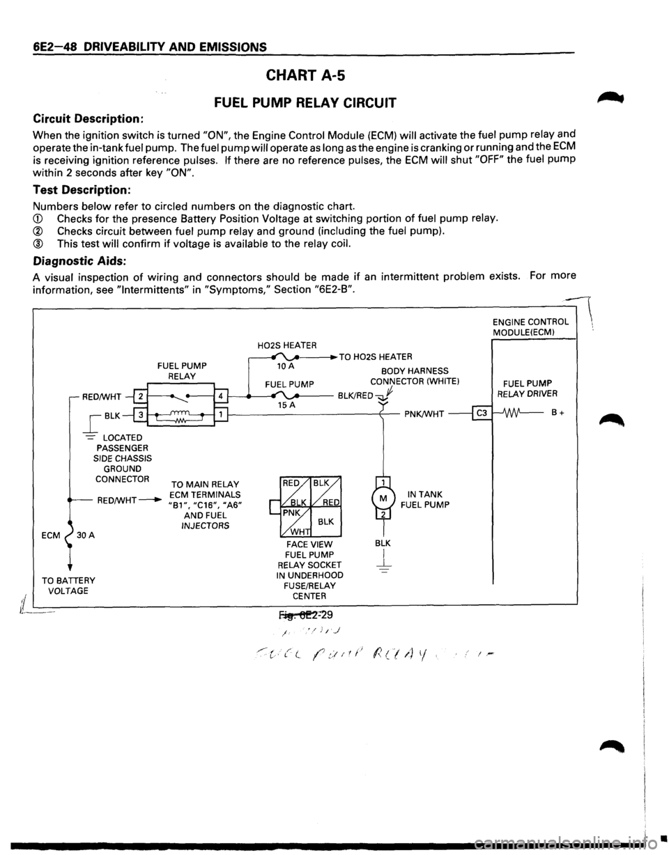
CHART A-5
FUEL PUMP RELAY CIRCUIT
Circuit Description:
When the ignition switch is turned "ON", the Engine Control Module (ECM) will activate the ft:Jel pump relay and
operate the in-tank
fuel pump. The fuel pump will operate as long as the engine is cranking or running and the ECM
is receiving ignition reference pulses. If there are no reference pulses, the ECM will shut "OFF" the fuel pump
within 2 seconds after key
"ON".
Test Description:
Numbers below refer to circled numbers on the diagnostic chart.
CD Checks for the presence Battery Position Voltage at switching portion of fuel pump relay.
® Checks circuit between fuel pump relay and ground (including the fuel pump).
® This test will confirm if voltage is available to the relay coil.
Diagnostic Aids:
A visual inspection of wiring and connectors should be made if an intermittent problem exists. For more
information, see
"lntermittents" in "Symptoms," Section "6E2-B".
ECM
FUEL PUMP
RELAY
H02S HEATER _. ___ .,.TO H02S HEATER
10 A BODY HARNESS CONNECTOR (WHITE)
RED/WHT 1---_.__.., '"..._.. __ BLK!RED...J
_[BLK
-= LOCATED PASSENGER SIDE CHASSIS
GROUND
CONNECTOR
TO MAIN RELAY
RED/WHT---+-ECM TERMINALS "81", "C16", 11A6" AND FUEL INJECTORS
FACE VIEW FUEL PUMP RELAY SOCKET
BLK
j__
IN TANK FUEL PUMP
TO BATIERY IN UNDERHOOD ENGINE
CONTRO:-- MODULE(ECM) ·.
FUEL PUMP RELAY DRIVER
8+
VOLTAGE
FUSE/RELAY
i L---------------------------C-EN_T_E_R _______________________ ~
lL---f~. 6E2=29
/
'"·:c·t( (7.::!11t.~ l<(/1) 1/. i-
•
Page 754 of 1928
6E2-58 DRIVEABILITY AND EMISSIONS
Circuit Description:
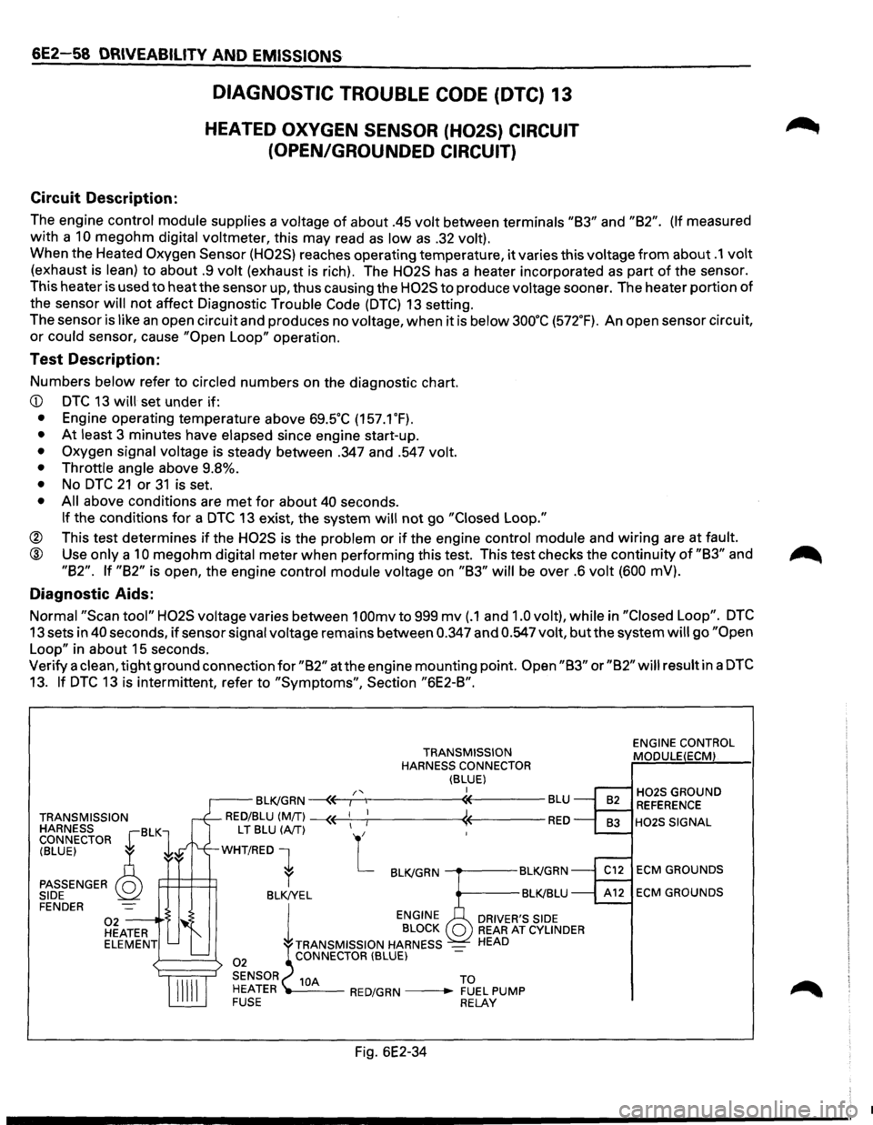
DIAGNOSTIC TROUBLE CODE (DTC) 13
HEATED OXYGEN SENSOR (H02S) CIRCUIT
(OPEN/GROUNDED CIRCUIT)
The engine control module supplies a voltage of about .45 volt between terminals "83" and "82". (If measured
with a
10 megohm digital voltmeter, this may read as low as .32 volt).
When the Heated Oxygen Sensor (H02S) reaches operating temperature, it varies this voltage from about .1 volt
(exhaust is lean) to about .9 volt (exhaust is rich). The H02S has a heater incorporated as part of the sensor.
This heater is used to
heatthe sensor up, thus causing the H02S to produce voltage sooner. The heater portion of
the sensor
will not affect Diagnostic Trouble Code (DTC) 13 setting.
The sensor
is like an open circuit and produces no voltage, when it is below 3oo·c (572.F). An open sensor circuit,
or could sensor, cause "Open Loop" operation.
Test Description:
Numbers below refer to circled numbers on the diagnostic chart.
• At least 3 minutes have elapsed since engine start-up.
• Oxygen signal voltage is steady between .347 and .547 volt.
• Throttle angle
above 9.8%.
• No DTC 21 or 31 is set.
• All above conditions are met for about 40 seconds.
If the conditions for a DTC 13 exist, the system will not go "Closed Loop."
® This test determines if the H02S is the problem or if the engine control module and wiring are at fault.
@ Use only a 10 megohm digital meter when performing this test. This test checks the continuity of "83" and
"82". If "82" is open, the engine control module voltage on "83" will be over .6 volt (600 mV).
Diagnostic Aids:
Normal "Scan tool" H02S voltage varies between 1 OOmv to 999 mv (.1 and 1.0 volt), while in "Closed Loop". DTC
13 sets in 40 seconds, if sensor signal voltage remains between 0.347 and 0.547 volt, but the system will go "Open
Loop"
in about 15 seconds.
Verify a
clean, tight ground connection for "82" at the engine mounting point. Open "83" or "82" will result in a DTC
13. If DTC 13 is intermittent, refer to "Symptoms", Section "6E2-8".
TRANSMISSION
HARNESS BLK CONNECTOR r 1
TRANSMISSION
HARNESS CONNECTOR
(BLUE) I /'< r--BLK/GRN ~~,---.,------«----BLU
RED/BLU (MIT) --« ! « RED
(BLUE) ~
PASSENGER Q SIDE
L T BLU (A/T) L
WHT/RED 1
P=H=~ r BLK/GRN ---.---BLK!GRN
BLK!YEL BLK!BLU FENDER
02 -----·'$ HEATER ELEMENT
02
l
ENGINE
BLOCK
TRANSMISSION HARNESS
-CONNECTOR (BLUE)
DRIVER'S SIDE REAR AT CYLINDER HEAD
SENSOR 10A TO
HEATER ---RED/GRN --• FUEL PUMP FUSE RELAY
Fig. 6E2-34
ENGINE CONTROL
MODULE(ECM)
H02S GROUND REFERENCE
H02S SIGNAL
ECM GROUNDS
ECM GROUNDS
•