heater ISUZU TROOPER 1995 Repair Manual
[x] Cancel search | Manufacturer: ISUZU, Model Year: 1995, Model line: TROOPER, Model: ISUZU TROOPER 1995Pages: 1928
Page 1235 of 1928
OFF
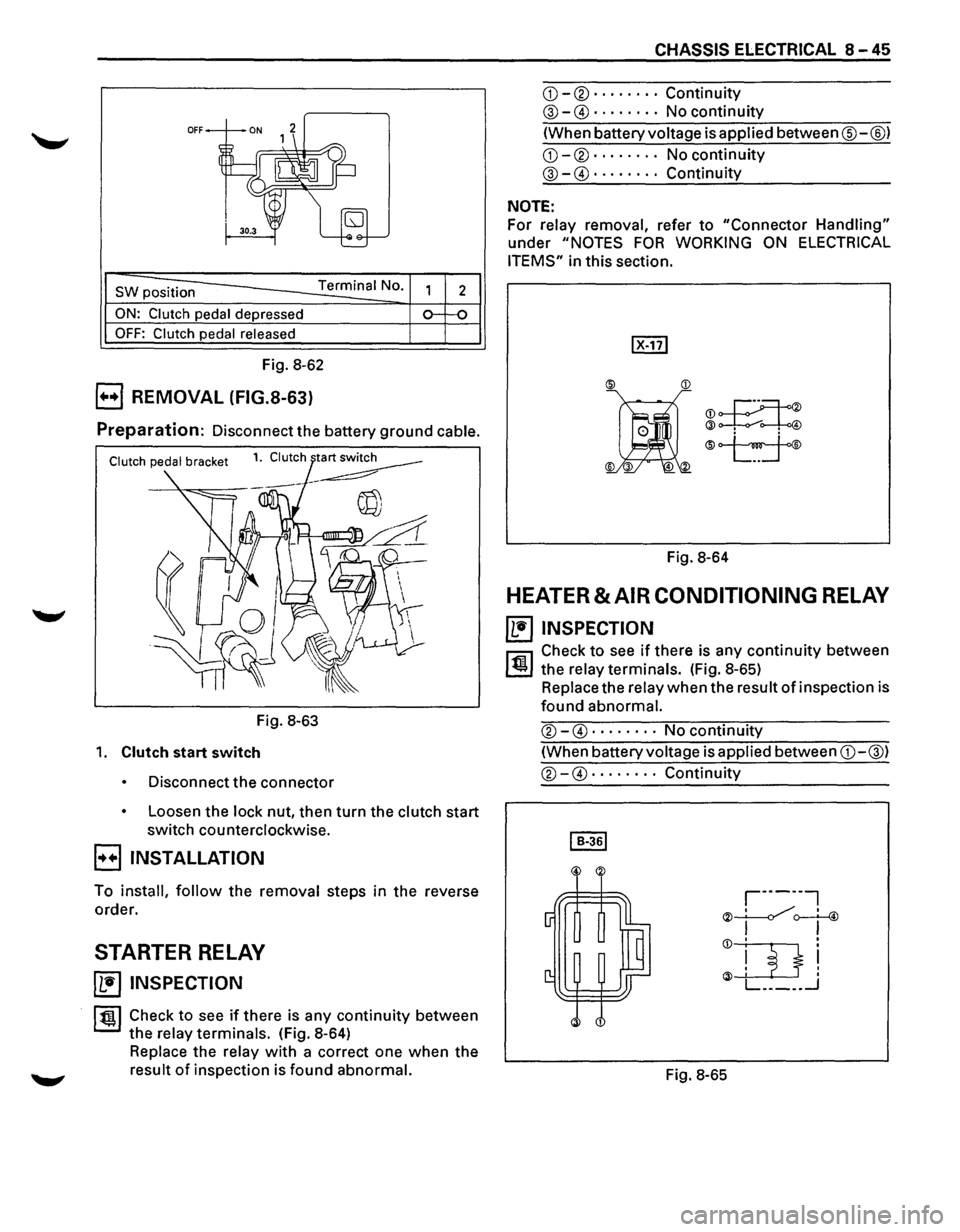
SW position Terminal No.
ON: Clutch pedal depressed
OFF: Clutch pedal released
Fig. 8-62
B REMOVAL (FIG.S-63)
2
Preparation: Disconnect the battery ground cable.
Fig. 8-63
1. Clutch start switch
Disconnect the connector
Loosen the lock nut, then turn the clutch start
switch counterclockwise.
B INSTALLATION
To install, follow the removal steps in the reverse
order.
STARTER RELAY
~ INSPECTION
ltgl Check to see if there is any continuity between
the relay terminals. (Fig. 8-64)
Replace the relay with a correct one when the
result of inspection is found abnormal.
CHASSIS ELECTRICAL 8-45
CD-®······ · · Continuity
@-G)· . · · · · .. No continuity
(When battery voltage is applied between®-@)
CD-®· · · · · · · · No continuity
@-G)· · · · · · · · Continuity
NOTE:
For relay removal, refer to "Connector Handling"
under "NOTES FOR WORKING ON ELECTRICAL
ITEMS"
in this section.
®JI
@~
®
Fig. 8-64
HEATER & AIR CONDITIONING RELAY
~ INSPECTION
l'fll Check to see if there is any continuity between
~ the relay terminals. (Fig. 8-65)
Replace the relay when the result of inspection is
found abnormal.
®-G) ..... · .. No continuity
(When battery voltage is applied between CD-@)
®-G) .... · · .. Continuity
Fig. 8-65
Page 1264 of 1928
8-74 CHASSIS ELECTRICAL
FOG LIGHT SWITCH
~ INSPECTION
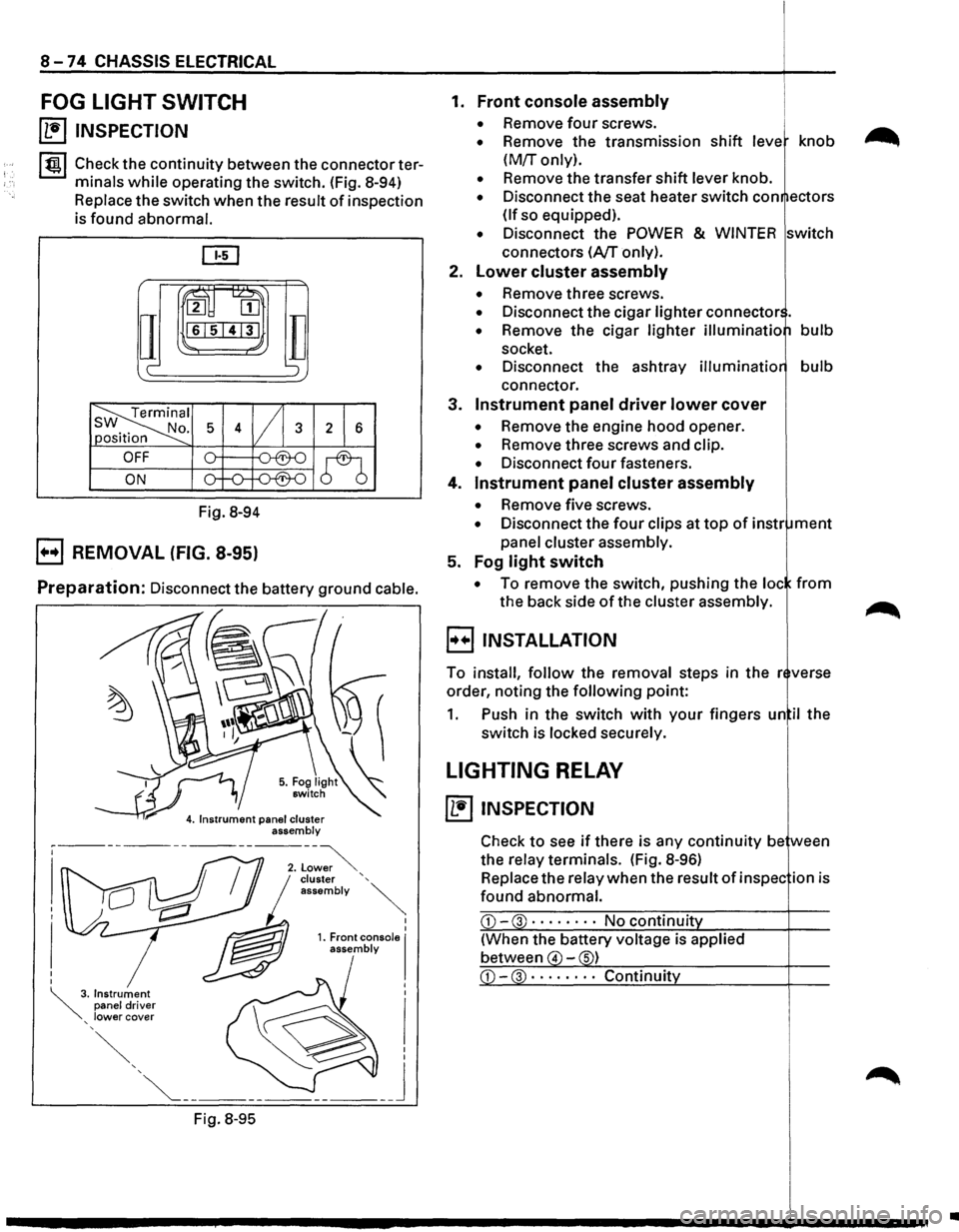
I tgj Check the continuity between the connector ter
minals
while operating the switch. (Fig. 8-94)
Replace the switch when the result of inspection
is found abnormal.
ru~
IT
2 [II
161514131
c-
Fig. 8-94
B REMOVAL (FIG. 8-95)
TI ';
Preparation: Disconnect the battery ground cable.
Fig.
8-95
I I 1. Front console I assembly
1. Front console assembly
• Remove four screws.
• Remove the transmission shift leve knob
(M!r only).
• Remove the transfer shift lever knob.
• Disconnect the seat heater switch con ectors
(If so equipped).
• Disconnect the POWER & WINTER switch
connectors
(A/T only).
2.
Lower cluster assembly
• Remove three screws.
• Disconnect the cigar lighter connector .
• Remove the cigar lighter illuminatio bulb
socket.
• Disconnect the ashtray illuminatio bulb
connector.
3.
Instrument panel driver lower cover
• Remove the engine hood opener.
• Remove three screws and clip.
• Disconnect four fasteners.
4.
Instrument panel cluster assembly
• Remove five screws.
• Disconnect the four clips at top of instr ment
panel cluster assembly.
5. Fog
light switch
• To remove the switch, pushing the loc from
the back side of the cluster assembly.
B INSTALLATION
To install, follow the removal steps in the r verse
order, noting the
following point:
1. Push in the switch with your fingers un il the
switch is locked securely.
LIGHTING RELAY
~ INSPECTION
Check to see if there is any continuity be ween
the relay terminals. (Fig.
8-96)
Replace the relay when the result of in spec ion is
found abnormal.
CD-3 · · · · • · · · No continuit
(When the battery voltage is applied
between
4 -s)
•
Page 1444 of 1928
8-254 CHASSIS ELECTRICAL
POWER DOOR MIRROR
GENERAL DESCRIPTION
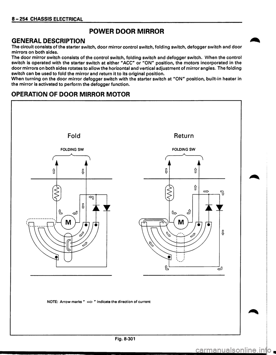
The circuit consists of the starter switch, door mirror control switch, folding switch, defogger switch and door
mirrors on both sides.
The
door mirror switch consists of the control switch, folding switch and defogger switch. When the control
switch is operated with the starter switch at either
"ACC" or "ON" position, the motors incorporated in the
door mirrors on both sides rotates to allow the horizontal and vertical adjustment of mirror angles. The folding
switch can
be used to fold the mirror and return it to its original position.
When turning on the
door mirror defogger switch with the starter switch at "ON" position, built-in heater in
the
mirror is activated to perform the defogger function.
OPERATION OF DOOR MIRROR MOTOR
Fold Return
FOLDING SW FOLDING SW
..---~A"""--
( '
---~.A.'---
( '
NOTE: Arrow marks " ~ " indicate the direction of current
Fig. 8-301
•
Page 1454 of 1928
8-264 CHASSIS ELECTRICAL
STARTER SWITCH
Refer to "START AND CHARGING" in this section.
DOOR MIRROR SWITCH ASSEMBLY
(CONTROL SWITCH, FOLDING
SWITCH
AND DEFOGGER SWITCH)
(FIG. 8-305)
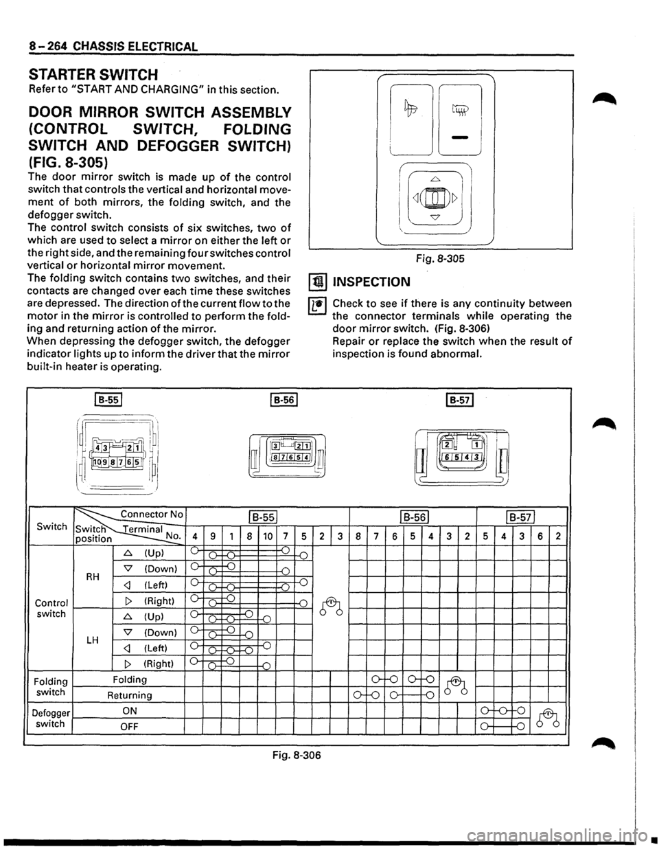
The door mirror switch is made up of the control
switch that controls the vertical and horizontal move
ment of both mirrors, the folding switch, and the
defogger switch.
The control switch consists of six switches, two of
which are used to select a mirror on either the left or
the right side, and the remaining four switches control
vertical or horizontal mirror movement.
The folding switch contains two switches, and their
contacts are changed over each time these switches
are depressed. The direction of the current flow to the
motor in the mirror is controlled to perform the fold
ing and returning action of the mirror.
When depressing the defogger switch, the defogger
indicator lights up to inform the driver that the mirror
built-in heater is operating.
I B-551 I B-561
i I I
!;l ~
LJ -J
I
I[~(@)~] J
Fig. 8-305
[!) INSPECTION
IL•I Check to see if there is any continuity between
the connector terminals while operating the
door mirror switch. (Fig. 8-306)
Repair or replace the switch when the result of
inspection is found abnormal.
I B-571
r .·~·· I ~ru·l
~~J!]}I ~ rroo~~l]
i !)~~1,1
a m
I ~ I ffi ;!sl7l6lsl41 ~ l~ lll"L•I'J'I•J ~~~
~' I J )
~0 ls-ssl IB-561 IB-571 Switch
N 4 9 1 8 10 7 5 2 3 8 7 6 5 4 3 2 5 4 3 6 2 o.
6. (Up) ~ ).. ...( ) .(")
'7 (Down) 0 c .) D RH c _.)
~ switch 6. (Up) c ~ -o ()-f-(l-
'7 (Down) 0 ( ) D LH c _.)
Folding Folding o-f-0 o--()
~ switch
Returning ()-Lo 0 0
Defogger ON o-'-0-
0
~ switch OFF 0 D
Fig. 8-306
•
Page 1457 of 1928
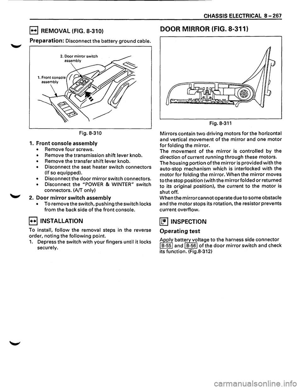
E) REMOVAL (FIG. 8-310)
Preparation: Disconnect the battery ground cable.
2. Door mirror switch assembly
Fig. 8-310
1. Front console assembly
• Remove four screws.
• Remove the transmission shift lever knob.
• Remove the transfer shift lever knob.
• Disconnect the seat heater switch connectors
(If so equipped).
• Disconnect the door mirror switch connectors.
• Disconnect the "POWER & WINTER" switch
connectors.
(A/T only)
2. Door mirror switch assembly
• To remove the switch, pushing the switch locks
from the back side of the front console.
B INSTALLATION
To install, follow the removal steps in the reverse
order, noting the
following point.
1. Depress the switch with your fingers until it locks
securely.
CHASSIS ELECTRICAL 8-267
DOOR MIRROR (FIG. 8-311)
Fig. 8-311
Mirrors contain two driving motors for the horizontal
and vertical movement of the mirror and one motor
for folding the mirror.
The movement of the mirror is controlled by the
direction
of current running through these motors.
The housing portion
ofthe mirror is provided with the
auto-stop mechanism which is
interlocked with the
motor for folding the mirror. When the mirror moves
to the stop position (with the mirror folded or returned
to its original position), the current to the motor is
shut off.
When the
mirror cannot operate due to some obstacle
and the motor stops its rotation, the resistor prevents
current
overflow.
~ INSPECTION
Operating test
Apply battery voltage to the harness side connector
I B-ssl and I B-561 of the door mirror switch and check
its function. (Fig.8-312)
Page 1529 of 1928
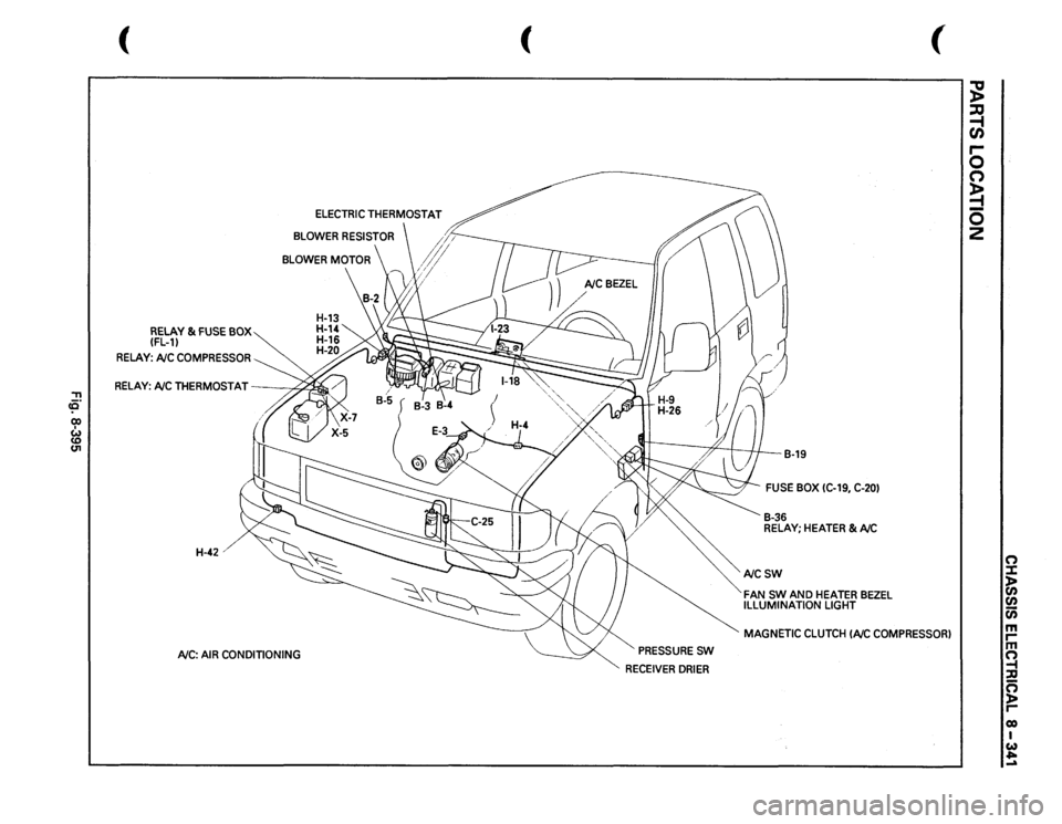
'"T1 cO' co w
RELAY
& FUSE
BOX
(FL-11
RELAY:
NC
COMPRESSOR
BLOWER
MOTOR
RELAY:
NCTHERMOSTAT
,,-;~
H-42'
NC:
AIR
CONDITIONING
(
PRESSURE
SW
RECEIVER
DRIER
B-19
FUSE
BOX
(C-19,
C-201
B-36 RELAY;
HEATER
& NC
NCSW FAN
SW
AND
HEATER
BEZEL
ILLUMINATION
LIGHT
(
MAGNETIC
CLUTCH
INC
COMPRESSOR)
;g ::0 ~ r-0 0 ~ 0 2
n :::J: )> en en Cii m rm ~ ::u n )> r-eo I w ~ ...a
Page 1532 of 1928
8-340 CHASSIS ELECTRICAL
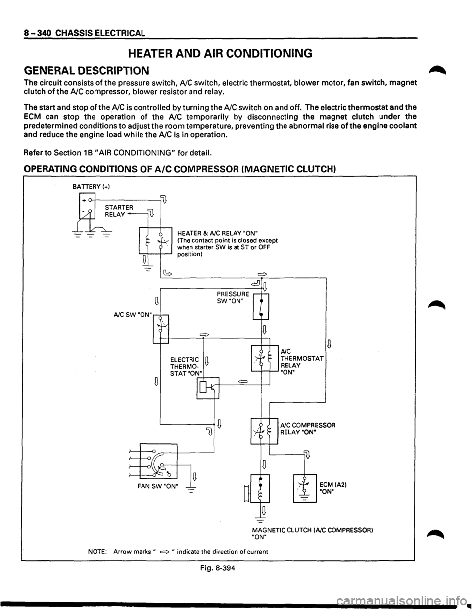
HEATER AND AIR CONDITIONING
GENERAL DESCRIPTION
The circuit consists of the pressure switch, NC switch, electric thermostat, blower motor, fan switch, magnet
clutch of the NC compressor, blower resistor and relay.
The start and stop of the NC is controlled by turning the NC switch on and off. The electric thermostat and the
ECM can stop the operation of the NC temporarily by disconnecting the magnet clutch under the
predetermined conditions
to adjust the room temperature, preventing the abnormal rise of the engine coolant
and reduce the engine load while the NC is in operation.
Refer
to Section 18 "AIR CONDITIONING" for detail.
OPERATING CONDITIONS OF A/C COMPRESSOR (MAGNETIC CLUTCH)
BATIERY(+)
--
~
A/C SW "ON"
~
HEATER & A/C RELAY "ON"
(The contact point is closed except
when starter SW is at ST or OFF position)
(S =:>
¢:!]
PRESSURE D
SW"ON"
¢:::l
~ FAN SW"ON"
u A/C THERMOSTAT
RELAY
"ON"
A/C COMPRESSOR
RELAY"ON"
ECM IA2l "ON"
MAGNETIC
CLUTCH lAIC COMPRESSOR)
"ON"
NOTE:
Arrow marks" =:> " indicate the direction of current
Fig. 8-394
~
1111
Page 1564 of 1928
8-374 CHASSIS ELECTRICAL
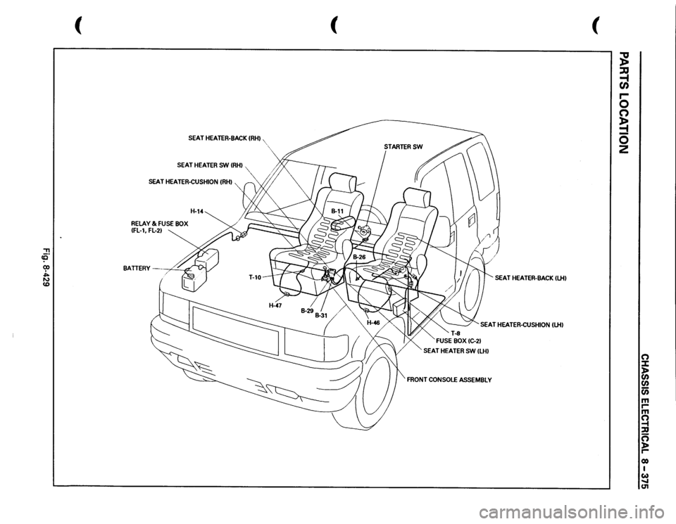
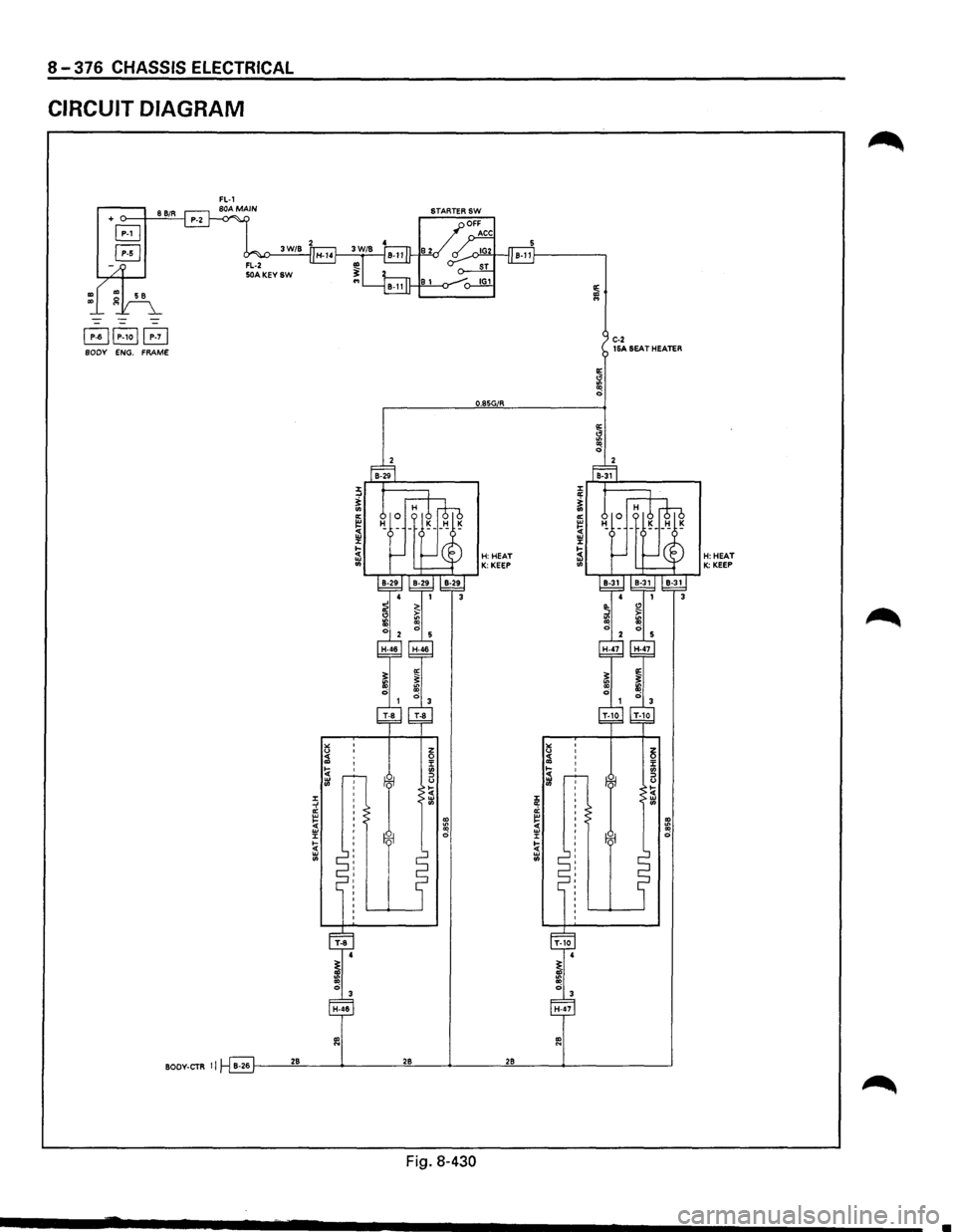
SEAT HEATER
GENERAL DESCRIPTION
The circuit consists of the starter switch, seat heater switch and the heat unit.
The seat heater is provided in driver's and front passenger seats
(as option). When the seat heater switch is
ON, the seat heater built in the seat back and cushion is switched on to warm the seats.
To prevent the seats
from being overheated, the circuit is fitted with a thermostat.
Ill
Page 1565 of 1928
, cE" 00 I ~ ~
SEAT
HEATER·BACK
IRHI,
',
SEAT
HEATER
SW
IRHI
"·
SEAT
HEATER-CUSHION
(RHI
RELAY
& FUSE
BOX
IFL-1,
FL-21
H-14
BATTERY
/ '
#..
(
(
SEAT
HEATER-BACK
ILHI
SEAT
HEATER-CUSHION
(lH)
SEAT
HEATER
SW
ILHI
FRONT
CONSOLE
ASSEMBLY
~ ~ r-0 0 ~ -0 2
n ::t 1: (/) c;; m rm ~ ::D 0 )> r-01) I w ..... C1l
Page 1566 of 1928
8-376 CHASSIS ELECTRICAL
CIRCUIT DIAGRAM
+ o---i--.!8'-!B~/R-'---j
~~P-1ojEj C-2 BODY ENG. FRAME 15A SEAT HEATER
O.BSG/R
BODY-CTR II B-26 1----'2"'8------------"2"-8--~._ ___ __,2-"8---~.._ _______ __,
Fig. 8-430
•