heater ISUZU TROOPER 1995 Owner's Manual
[x] Cancel search | Manufacturer: ISUZU, Model Year: 1995, Model line: TROOPER, Model: ISUZU TROOPER 1995Pages: 1928
Page 63 of 1928
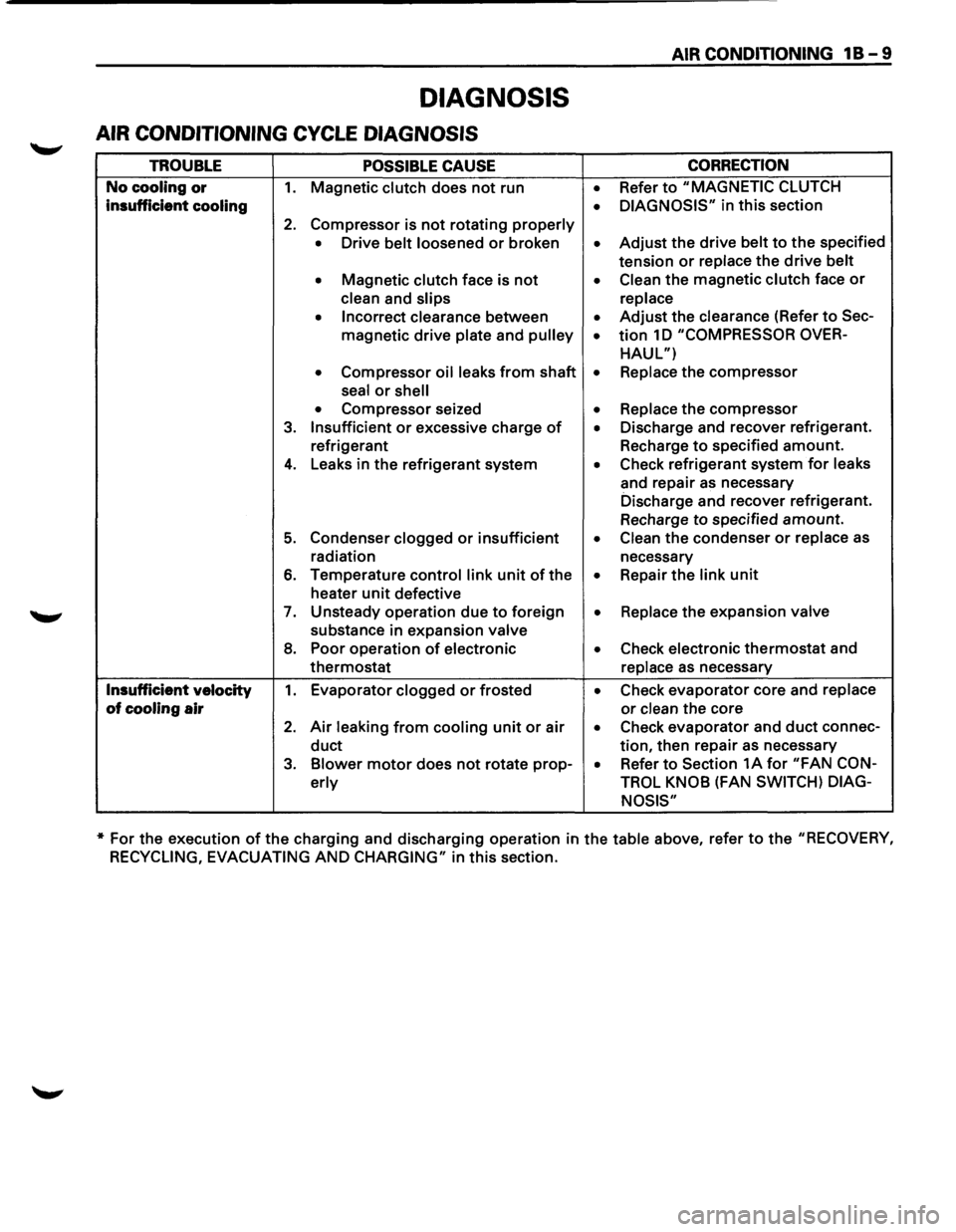
DIAGNOSIS
AIR CONDITIONING CYCLE DIAGNOSIS
TROUBLE POSSIBLE CAUSE
No cooling or 1. Magnetic clutch does not run
insufficient cooling
2. Compressor is not rotating properly
• Drive belt loosened or broken
• Magnetic clutch face is not
clean and slips
• Incorrect clearance between
magnetic
drive plate and pulley
• Compressor oil leaks from shaft
seal
or shell
• Compressor seized
3. Insufficient or excessive charge of
refrigerant
4. Leaks in the refrigerant system
5. Condenser clogged or insufficient
radiation
6. Temperature control link unit of the
heater
unit defective
7. Unsteady operation due to foreign
substance in expansion valve
8. Poor operation of electronic
thermostat
Insufficient velocity 1. Evaporator clogged or frosted
of cooling air
2. Air leaking from cooling unit or air
duct
3. Blower motor does not rotate prop-
erly
AIR CONDITIONING 1 B - 9
CORRECTION
• Refer to "MAGNETIC CLUTCH
• DIAGNOSIS" in this section
• Adjust the drive belt to the specified
tension
or replace the drive belt
• Clean the magnetic clutch face or
replace
• Adjust the clearance (Refer to Sec-
• tion 1 D "COMPRESSOR OVER-
HAUL")
• Replace the compressor
• Replace the compressor
• Discharge and recover refrigerant.
Recharge
to specified amount.
• Check refrigerant system for leaks
and repair
as necessary
Discharge and recover refrigerant.
Recharge
to specified amount.
• Clean the condenser or replace as
necessary
• Repair the link unit
• Replace the expansion valve
• Check electronic thermostat and
replace
as necessary
• Check evaporator core and replace
or clean the core
• Check evaporator and duct connec-
tion, then repair as necessary
• Refer to Section 1A for "FAN CON-
TROL KNOB
(FAN SWITCH) DIAG-
NOSIS"
* For the execution of the charging and discharging operation in the table above, refer to the "RECOVERY,
RECYCLING, EVACUATING
AND CHARGING" in this section.
Page 68 of 1928
18-14 AIR CONDITIONING
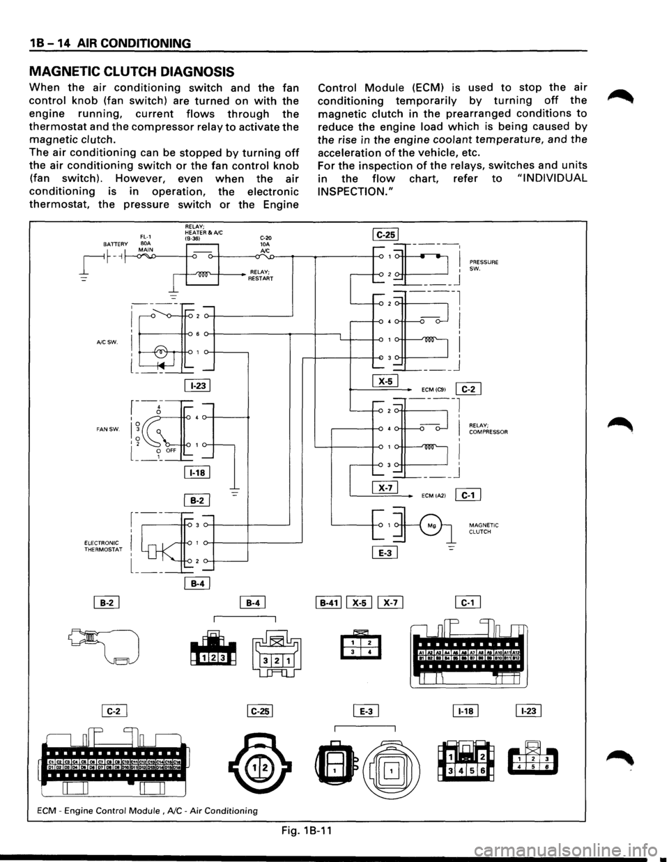
MAGNETIC CLUTCH DIAGNOSIS
When the air conditioning switch and the fan
control knob (fan switch) are turned on with the
engine running, current flows through the
thermostat and the compressor relay to activate the
magnetic clutch.
The air conditioning can be stopped by turning off
the air conditioning switch or the fan control knob
(fan switch). However, even when the air
conditioning is in operation, the electronic
thermostat, the pressure switch or the Engine
BATTER y
~
A/C SW.
FAN SW.
FL-1 BOA MAIN -.Y""'
I
RELAY; HEATER&A/C (8-36)
-
·~
~-----;::: -
I ,--<> -v--ro 2
I 6
! -&r ro 1 l ~ .... --~-'---
11-231
r-g-I 4
I~ 0 I 2 1
l __ 9_ OFF -
lli!J
~
r-----3 I
I 1
I 2 -
ELECTRONIC ~ THERMOSTAT
l __ _
C-20 10A Jd.C
RELAY; RESTART
-=-
ECM -Engine Control Module , NC -Air Conditioning
Control Module (ECM) is used to stop the air
conditioning temporarily by turning off the
magnetic clutch in the prearranged conditions to
reduce the engine load which is being caused by
the rise in the engine coolant temperature, and the
acceleration of the vehicle, etc.
For
the inspection of the relays, switches and units
in the flow chart, refer to "INDIVIDUAL
INSPECTION."
,....-1
2 ......_
.....-=.-2
40. r-
1v-
3
......._ =--
~
I ___ j
PRESSURE
SW.
ECMIC91
~
---2 ----l
•o--
1v-
3
-~-@]
~1
L
[ill
I
I RELAY; COMPRESSOR
I
I I ___ j
ECMIA21 ~
:=:>
MAGNETIC
CLUTCH
,.----I In_ r-r
A1 Kl ., .. ...... A& .. A7 AI ld A10 A11A12 .... •• ., .. a1o an 112
'It!
~
~
Fig.1B-11
Page 69 of 1928
AIR CONDITIONING 1 B -15
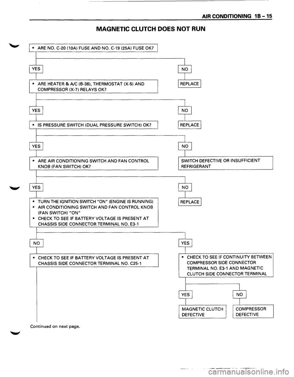
MAGNETIC CLUTCH DOES NOT RUN
• ARE NO. C-20 (10A) FUSE AND NO. C-19 (25A) FUSE OK?
•
ARE HEATER & A!C (B-36), THERMOSTAT (X-5) AND
COMPRESSOR (X-7) RELAYS OK?
•
ARE AIR CONDITIONING SWITCH AND FAN CONTROL
KNOB
(FAN SWITCH) OK?
•
TURN THE IGNITION SWITCH "ON" (ENGINE IS RUNNING)
• AIR CONDITIONING SWITCH
AND FAN CONTROL KNOB
(FAN SWITCH) "ON"
• CHECK TO SEE IF BATTERY VOLTAGE IS PRESENT AT
CHASSIS SIDE CONNECTOR TERMINAL NO. E3-1
• CHECK TO SEE IF BATTERY VOLTAGE IS PRESENT AT
CHASSIS SIDE CONNECTOR TERMINAL NO. C25-1
Continued on next page.
SWITCH DEFECTIVE OR INSUFFICIENT
REFRIGERANT
• CHECK TO
SEE IF CONTINUITY BETWEEN
COMPRESSOR SIDE CONNECTOR
TERMINAL NO.
E3-1 AND MAGNETIC
CLUTCH SIDE CONNECTOR TERMINAL
Page 72 of 1928
18-18 AIR CONDITIONING
~ INDIVIDUAL INSPECTION
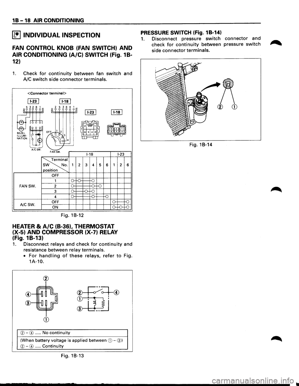
FAN CONTROL KNOB (FAN SWITCH) AND
AIR CONDITIONING (A/C) SWITCH (fig. 1 B-
12)
1. Check for continuity between fan switch and
AJC switch side connector terminals.
ITill [Eill
[fill [Eill ~ 11''''''·11
'"" ~~ -
-~
i'~EHffil ILLUMI-, . cl 3 LI LJ NATION I I 4
L_ _ _j AICSW. FAN SW. 1-18 1-23
~
1
2 3 4 5 6 1 2
n
.
OFF
1 0
FAN SW. 2 [)_ -11--::=:;-
3 o-~ -n. -o
4 [)_ -o
OFF (). f--NCSW. ON [)_
Fig. 18-12
HEATER & A/C (B-36), THERMOSTAT
(X-5) AND COMPRESSOR (X-7) RELAY
(fig. 18-13)
:;,_
6
-f)
-:;::;
1. Disconnect relays and check for continuity and
resistance between
relay terminals.
•
For handling of these relays, refer to Fig.
1A-10.
@
@
®
CD
®-0 ..... No continuity
(When battery voltage is applied between CD-@)
®-0 ..... Continuity
Fig. 18-13
PRESSURE SWITCH (Fig. 18-14)
1. Disconnect pressure switch connector and
check
for continuity between pressure switch
side connector terminals.
Fig. 18-14
Page 87 of 1928
AIR CONDITIONING 1 B -33
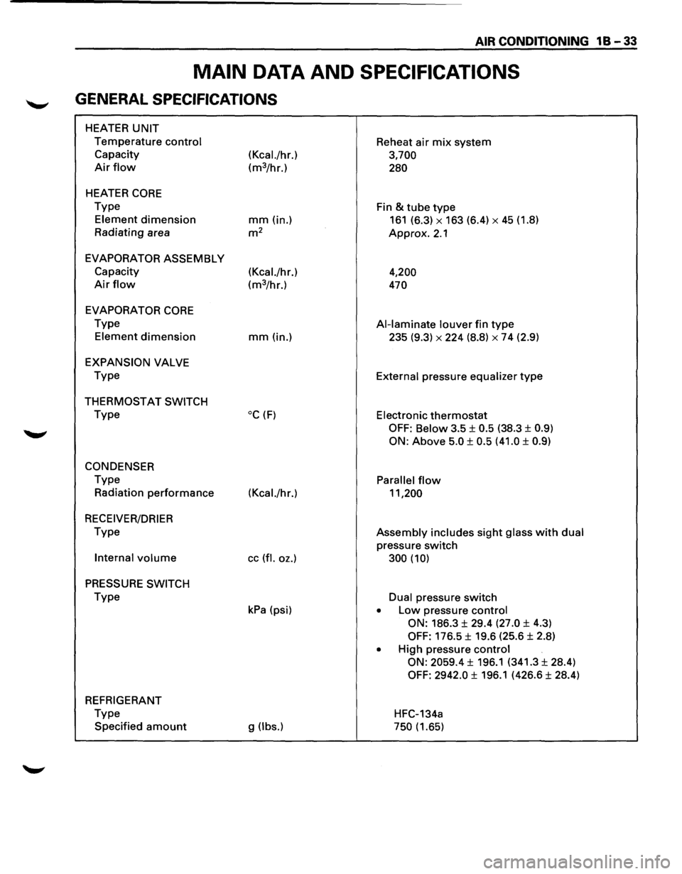
MAIN DATA AND SPECIFICATIONS
GENERAL SPECIFICATIONS
HEATER UNIT
Temperature control Reheat air mix system
Capacity
(Kcal./hr.) 3,700
Air flow (m3/hr.) 280
HEATER CORE
Type
Fin & tube type
Element dimension mm (in.) 161 (6.3) X 163 (6.4) X 45 (1.8)
Radiating area
m2 Approx. 2.1
EVAPORATOR ASSEMBLY
Capacity (Kcal./hr.)
4,200
Air flow (m3/hr.) 470
EVAPORATOR
CORE
Type Al-laminate louver fin type
Element dimension mm(in.) 235 (9.3) X 224 (8.8) X 7 4 (2.9)
EXPANSION VALVE
Type
External pressure equalizer type
THERMOSTAT SWITCH
Type oc (F) Electronic thermostat
OFF: Below 3.5 ± 0.5 (38.3 ± 0.9)
ON:
Above 5.0 ± 0.5 (41.0 ± 0.9)
CONDENSER
Type Parallel flow
Radiation performance (Kcal./hr.) 11,200
RECEIVER/DRIER
Type Assembly includes sight glass with dual
pressure switch
Internal volume cc (fl. oz.) 300 (10)
PRESSURE SWITCH
Type Dual pressure switch
kPa (psi) • Low pressure control
ON:
186.3 ± 29.4 (27.0 ± 4.3)
OFF: 176.5 ± 19.6 (25.6 ± 2.8)
• High pressure control
ON: 2059.4
± 196.1 (341.3 ± 28.4)
OFF: 2942.0 ± 196.1 (426.6 ± 28.4)
REFRIGERANT
Type
HFC-134a
Specified
amount g (lbs.) 750 (1.65)
Page 563 of 1928
4. Exhaust Gas Recirculation pipe and valve
• Tighten each fixing bolt to the specified torque.
Valve fixing bolt
1«1 Torque N·m (lb·in) 8 (69)
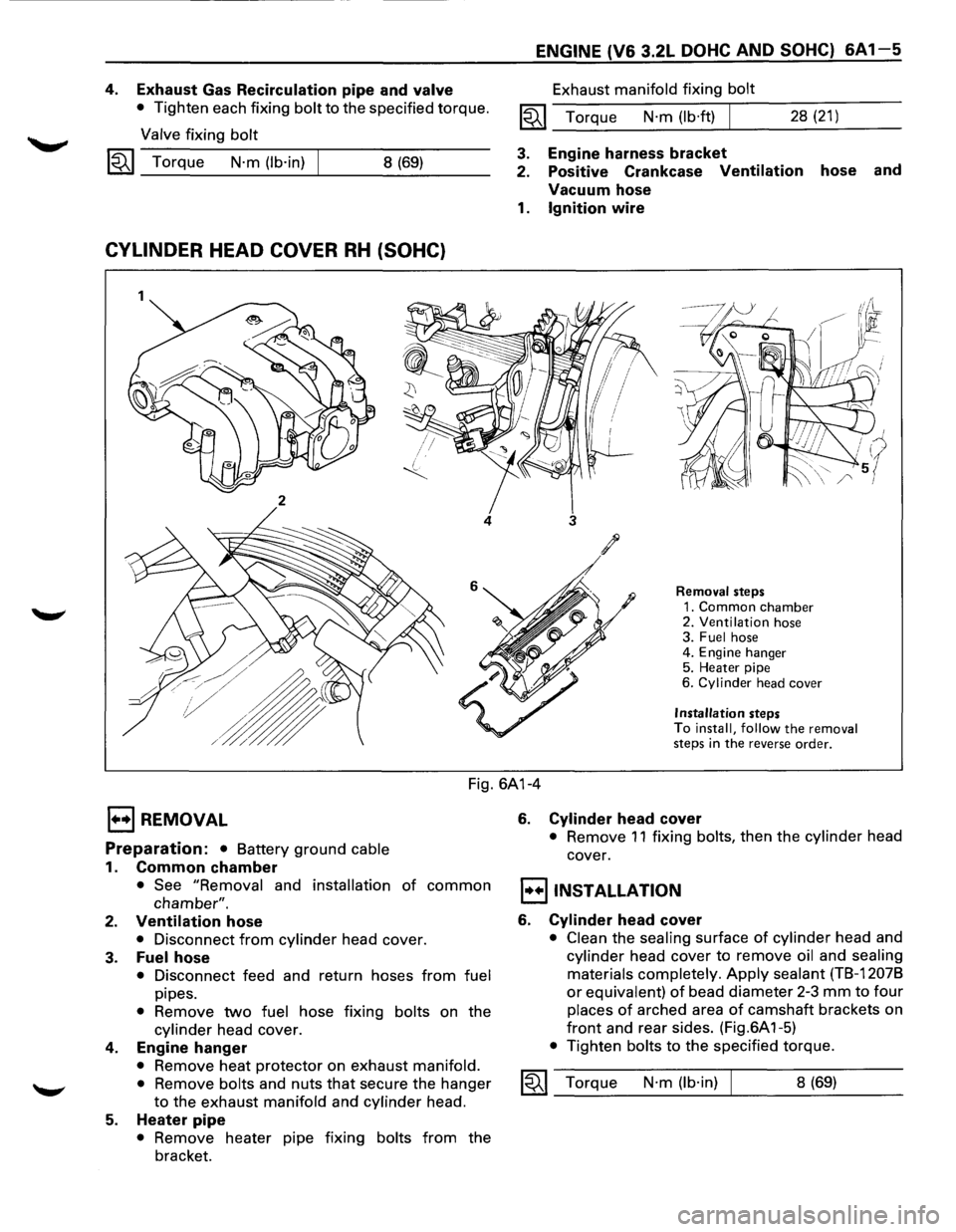
CYLINDER HEAD COVER RH (SOHC)
1
2
4
ENGINE (V6 3.2L DOHC AND SOHC) 6A1-5
Exhaust manifold fixing bolt
1«1 Torque N·m (lb·ft) I 28 (21)
3. Engine harness bracket
2. Positive Crankcase
Ventilation hose and
Vacuum hose
1. Ignition wire
3
Removal steps
1. Common chamber 2. Ventilation hose
3. Fuel hose
4. Engine hanger
5. Heater pipe
6.
Cylinder head cover
Installation steps
To install, follow the removal
steps in the reverse order.
Fig. 6A1-4
EJ REMOVAL
Preparation: • Battery ground cable
1. Common chamber
• See "Removal and installation of common
chamber".
2. Ventilation hose
• Disconnect from cylinder head cover.
3. Fuel hose
• Disconnect feed and return hoses from fuel
pipes.
• Remove two fuel hose fixing bolts on the
cylinder head cover.
4. Engine hanger
• Remove heat protector on exhaust manifold.
•
Remove bolts and nuts that secure the hanger
to the exhaust manifold and cylinder head.
5. Heater pipe
• Remove heater pipe fixing bolts from the
bracket.
6. Cylinder head cover
• Remove 11 fixing bolts, then the cylinder head
cover.
I•+IINSTALLATION
6. Cylinder head cover
• Clean the sealing surface of cylinder head and
cylinder head cover to remove oil and sealing
materials completely.
Apply sealant (TB-12078
or equivalent) of bead diameter 2-3 mm to four
places of arched area of camshaft brackets on
front and rear sides. (Fig.6A 1-5)
• Tighten bolts to the specified torque.
1«1 Torque N·m (lb·in) 8 (69)
Page 564 of 1928
6A1-6 ENGINE (V6 3.2L DOHC AND SOHC)
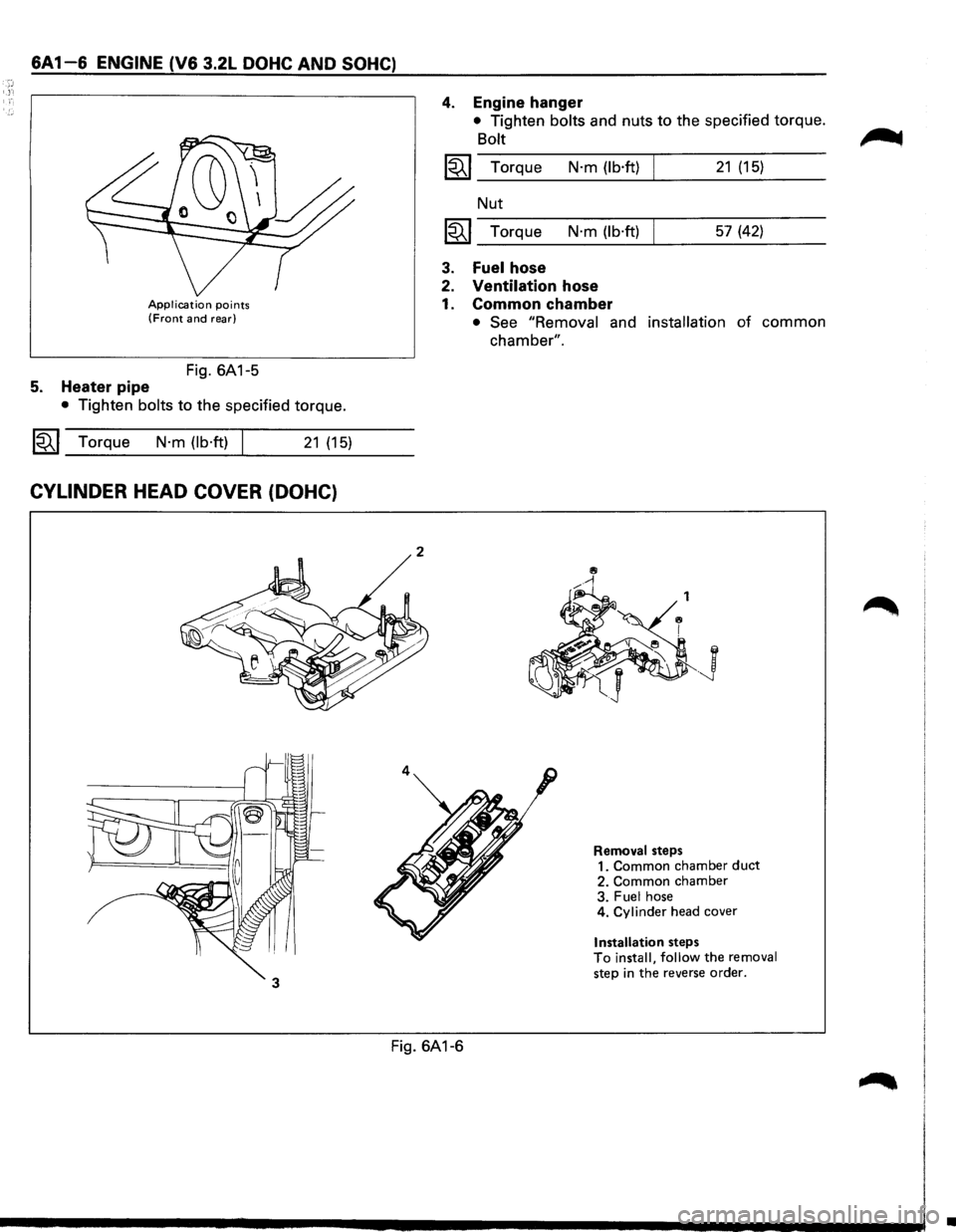
Application points (Front and rear)
Fig. 6A1-5
5. Heater pipe
• Tighten bolts to the specified torque.
~~~ Torque N·m (lb·ft) I 21 (15)
CYLINDER HEAD COVER (DOHC)
2
4
4. Engine hanger
• Tighten bolts and nuts to the specified torque.
Bolt
~~~ Torque N·m (lb·ft) 21 (15)
Nut
~~~ Torque N·m (lb·ft) 57 (42)
3. Fuel hose
2. Ventilation hose
1. Common chamber
• See "Removal and installation of common
chamber".
.J
Removal steps
1. Common chamber duct 2. Common chamber
3. Fuel hose
4. Cylinder head cover
Installation steps To install, follow the removal step in the reverse order.
Fig. 6A1-6
•
Page 601 of 1928
EJ REMOVAL
Preparation: • Remove engine hood.
• Drain radiator Engine Coolant.
• Disconnect battery ground cable.
1. Air cleaner assembly
2. Radiator upper fan shroud
• Remove from radiator.
3. Radiator fan assembly
• Remove four nuts, then the radiator fan
assembly.
4. Accelerator Pedal cable
• Disconnect from throttle body and cable
bracket.
5. Canister vacuum hose
6. Vacuum booster hose
• Disconnect from common chamber.
7. Connectors
• Disconnect from Manifold Absolute Pressure,
canister Vacuum Switching
Valve (VSV),
Exhaust Gas Recirculation VSV,
Intake Air
Temperature and ground cable.
8. High tension cables
• Disconnect from cylinder head cover.
9. Ignition Control Module assembly
• Disconnect three Electronic Ignition con
nectors.
• Remove three Electronic Ignition bracket fixing
bolts, and remove Electronic Ignition assembly
with high tension cables.
10. Throttle body
• Remove four fixing bolts.
11. Vacuum hoses
• Disconnect vacuum hoses on canister VSV and
Exhaust Gas Recirculation VSV
from the
throttle body.
12. Positive Crankcase Ventilation hose
• Disconnect from common chamber.
13. Fuel Pressure Control Valve vacuum hose
• Disconnect from common chamber.
14. Evaporative Emission Canister Purge hose
• Disconnect from common chamber.
15. Exhaust Gas Recirculation assembly
16. Common chamber
• Remove six bolts, two nuts and four bracket
fixing bolts, then remove the
common
chamber.
17. Throttle body
• Disconnect Engine Coolant hose from throttle
body.
• Disconnect Idler Air Control Valve and Throttle
Position Sensor connectors.
ENGINE (V6 3.2L DOHC AND SOHC) 6A1-43
18. Fuelhoses
• Disconnect feed and return fuel hoses from fuel
pipes, and remove two bracket fixing bolts on
the cylinder head cover.
19. Fuel injector connectors
• Disconnect connectors from injectors.
• Disconnect thermo sensor connector.
20. Intake manifold
• Remove two fixing bolts and four nuts.
21. Engine Coolant manifold
• Disconnect heater hose.
• Remove four fixing bolts.
22. Power steering pump drive belt
23. Air Conditioning compressor drive belt
24. Generator drive belt
25. Power steering pump
26.
Fan pulley assembly
27. Crankshaft pulley assembly
~ • Using special tool J-8614-01, hold crankshaft
~ pulley.
•
Remove center bolt, then the pulley.
28. Oil cooler hose
• Remove two cooler hose bracket fixing bolts on
the timing
belt cover.
29. Timing belt cover
30. Pusher
\fl CAUTION:
VI The pusher prevents air from entering the oil
chamber. Its rod must always be facing upward.
31. Timing belt
\fl CAUTIONS:
VI 1) Do not bend or twist the belt, otherwise its
core
could be damaged. The belt should not
be bent at a radius less than 30mm.
2) Do not allow oil or other chemical substances
to come in contact with the belt. They will
shorten the belt life.
3) Do not attempt to pry or stretch the belt with a
screwdriver
or any other tool during
installation.
4) Store timing belt in a cool and dark place.
Never expose the
belt to direct sunlight or
heat.
32. Cylinder head cover
• Remove 11 fixing bolts, then the cylinder head
cover.
33. Power steering pump bracket
• Disconnect ground cable from bracket.
• Remove five fixing bolts, then the bracket.
34. Exhaust front pipe
35.
Level gage guide tube fixing bolt
• Remove from cylinder head.
36. Cylinder head
Page 602 of 1928
'.:.:.
6A1-44 ENGINE (V6 3.2L DOHC AND SOHC)
1••1 INSTALLATION
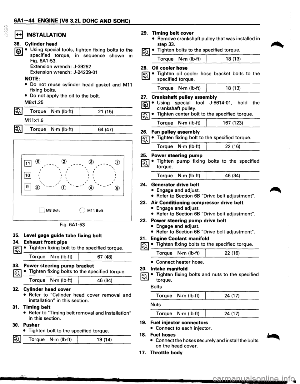
36. Cylinder head
l"i:a\1 • Using special tools, tighten fixing bolts to the
~ specified torque, in sequence shown in
Fig.
6A 1-53.
Extension wrench: J-39252
Extension wrench: J-24239-01
NOTE:
• Do not reuse cylinder head gasket and M11
fixing bolts.
• Do not apply the oil to the bolt.
M8x1.25
1~1 Torque N·m (lb·ft)
M11x1.5
21 (15)
~~~ Torque N·m (lb·ft) 64 (47)
[ill ® ® @ , , , I I I
~
I
I I
I I
I I I
I I
I I I
I I
I
0
' , , ' ' , ' , ' ® '-~ CD @
M8 Bolt QM11Bolt
Fig. 6A1-53
35. Level gage guide tube fixing bolt
34. Exhaust front pipe
' '
, ,
(j)
I
I
I
@
~~~ • Tighten fixing bolt to the specified torque.
Torque
N·m (lb·ft) I 67 (48)
33. Power steering pump bracket
~~~· Tighten fixing bolts to the specified torque.
Torque
N·m (lb·ft) I 46 (34)
32. Cylinder head cover
• Refer to "Cylinder head cover removal and
installation" in this section.
31. Timing belt
• Refer to "Timing belt removal and installation"
in this section.
30. Pusher
• Tighten bolt to the specified torque.
1~1 Torque N·m (lb·ft) I 19 (14)
29. Timing belt cover
• Remove crankshaft pulley that was installed in
step
33.
~~~· Tighten bolts to the specified torque.
Torque
N·m (lb·ft) I 18 (13)
28. Oil cooler hose
~ • Tighten oil cooler hose bracket bolts to the
~ specified torque.
Torque
N·m(lb·ft) I 18(13)
27. Crankshaft pulley assembly
l"i:a\1 • Using special tool J-8614-01, hold the
~ crankshaft pulley.
~~~· Tighten center bolt to the specified torque.
Torque
N·m (lb·ft) I 167 (123)
26. Fan pulley assembly
~~~ • Tighten fixing bolt to the specified torque.
Torque
N·m (lb·ft) I 22 (16)
25. Power steering pump
~ • Tighten pump fixing bolts to the specified
~ torque.
Torque
N-m (lb·ft) 46 (34)
24. Generator drive belt
• Engage and adjust.
• Refer to Section 68 "Drive belt adjustment".
23. Air Conditioning compressor drive belt
• Engage and adjust.
• Refer to Section 68 "Drive belt adjustment".
22. Power steering pump drive belt
• Engage and adjust.
• Refer to Section 68 "Drive belt adjustment".
21. Engine Coolant manifold
~~~· Tighten fixing bolts to the specified torque.
Torque
N·m (lb·ft) J 22 (16)
• Connect heater hose.
20. Intake manifold
~ • Tighten fixing bolts and nuts to the specified
~ torque.
Bolts
Torque N-m (lb·ft) 24 (17)
Nuts
Torque
N-m (lb·ft) 24 (17)
19. Fuel injector connectors
• Connect to each injector.
18. Fuelhoses
• Connect the hoses securely and install the bolts
on the head cover.
17. Throttle body
..
Page 605 of 1928
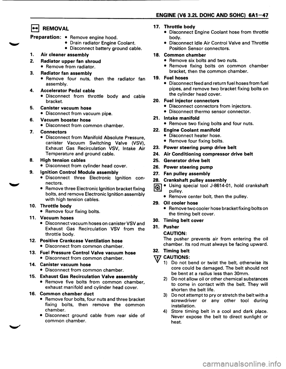
1••1 REMOVAL
Preparation: • Remove engine hood.
• Drain radiator Engine Coolant.
•
Disconnect battery ground cable.
1.
Air cleaner assembly
2. Radiator upper fan shroud
• Remove from radiator.
3. Radiator fan assembly
• Remove four nuts, then the radiator fan
assembly.
4. Accelerator Pedal cable
• Disconnect from throttle body and cable
bracket.
5. Canister vacuum hose
• Disconnect from vacuum pipe.
6.
Vacuum booster hose
• Disconnect from common chamber.
7. Connectors
• Disconnect from Manifold Absolute Pressure,
canister Vacuum Switching Valve (VSV),
Exhaust
Gas Recirculation VSV, Intake Air
Temperature and ground cable.
8. High tension cables
• Disconnect from cylinder head cover.
9. Ignition Control Module assembly
• Disconnect three Electronic Ignition con
nectors.
• Remove three Electronic Ignition bracket fixing
bolts, and remove Electronic
Ignition assembly
with high tension cables.
10. Throttle body
• Remove four fixing bolts.
11.
Vacuum hoses
• Disconnect vacuum hoses on canister VSV and
Exhaust
Gas Recirculation VSV from the
throttle body.
12.
Positive Crankcase Ventilation hose
• Disconnect from common chamber.
13. Fuel Pressure
Control Valve vacuum hose
• Disconnect from common chamber.
14.
Canister vacuum hose
• Disconnect from common chamber.
15.
Exhaust Gas Recirculation Valve assembly
• Remove five bolts from common chamber,
exhaust manifold and cylinder head cover.
16.
Common chamber duct
• Remove four bolts, four nuts and three bracket
fixing bolts, then remove the
common
chamber.
• Disconnect ground cable from rear side of
common chamber.
ENGINE (V6 3.2L DOHC AND SOHC) 6A1 47
17. Throttle body
• Disconnect Engine Coolant hose from throttle
body.
• Disconnect Idle Air Control Valve and Throttle
Position Sensor connectors.
18.
Common chamber
• Remove six bolts and two nuts.
• Remove fixing bolts on common chamber
bracket, then the
common chamber.
19.
Fuelhoses
• Disconnect feed and return fuel hoses from fuel
pipes, and remove
two bracket fixing bolts on
the cylinder head cover.
20. Fuel injector connectors
• Disconnect connectors from injectors.
• Disconnect thermo sensor connector.
21.
Intake manifold
• Remove two fixing bolts and four nuts.
22. Engine
Coolant manifold
• Disconnect heater hose.
• Remove four fixing bolts.
23.
Power steering pump drive belt
24. Air Conditioning compressor drive belt
25. Generator drive belt
26. Power steering pump
27. Fan pulley assembly
28. Crankshaft pulley assembly
I®J • Using special tool J-8614-01, hold crankshaft
pulley.
•
Remove center bolt, then the pulley.
29. Oil cooler hose
• Remove two cooler hose bracket fixing bolts on
the timing belt cover.
30. Timing belt cover
31. Pusher
CAUTION:
The pusher prevents air from entering the oil
chamber. Its rod must always be facing upward.
32.
Timing belt
w CAUTIONS:
' 1) Do not bend or twist the belt, otherwise its
core could
be damaged. The belt should not
be bent at a radius less than 30mm.
2) Do not allow oil or other chemical substances
to come in contact
with the belt. They will
shorten the belt life.
3) Do not attempt to pry or stretch the belt with a
screwdriver
or any other tool during
installation.
4) Store timing belt in a cool and dark place.
Never expose the belt to direct sunlight
or
heat.