steering ISUZU TROOPER 1995 Manual PDF
[x] Cancel search | Manufacturer: ISUZU, Model Year: 1995, Model line: TROOPER, Model: ISUZU TROOPER 1995Pages: 1928
Page 227 of 1928
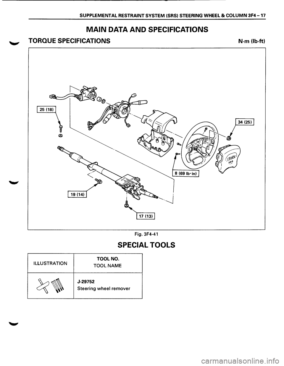
SUPPLEMENTAL RESTRAINT SYSTEM (SRS) STEERING WHEEL & COLUMN 3F4-17
MAIN DATA AND SPECIFICATIONS
TORQUE SPECIFICATIONS
Fig. 3F4-41
SPECIAL TOOLS
TOOL NO.
ILLUSTRATION TOOL
NAME
~~
J-29752
Steering wheel remover
N-m (lb.ft)
Page 280 of 1928
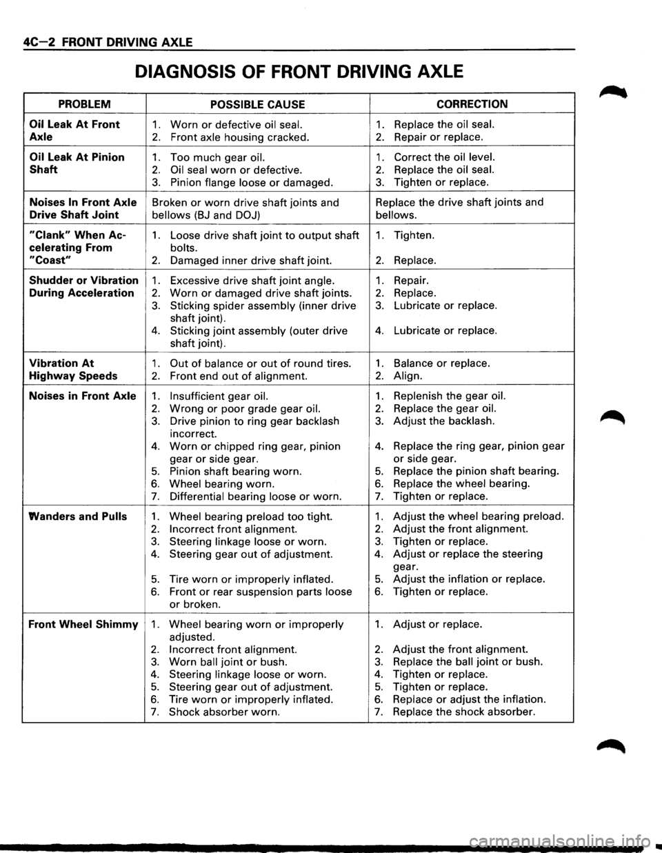
4C-2 FRONT DRIVING AXLE
DIAGNOSIS OF FRONT DRIVING AXLE
PROBLEM POSSIBLE CAUSE CORRECTION
Oil
Leak At Front 1. Worn or defective oil seal. 1. Replace the oil seal.
Axle 2. Front axle housing cracked. 2. Repair or replace.
Oil Leak At Pinion 1. Too much gear oil. 1. Correct the oil level.
Shaft 2. Oil seal worn or defective. 2. Replace the oil seal.
3. Pinion flange loose or damaged. 3. Tighten or replace.
Noises In Front Axle Broken or worn drive shaft joints and Replace
the drive shaft joints and
Drive Shaft Joint bellows (BJ and DOJ) bellows.
"Clank" When Ac-1. Loose drive shaft joint to output shaft 1. Tighten.
celerating From bolts.
"Coast" 2. Damaged inner drive shaft joint. 2. Replace.
Shudder or Vibration 1. Excessive drive shaft joint angle. 1. Repair.
During Acceleration 2. Worn or damaged drive shaft joints. 2. Replace.
3. Sticking spider assembly (inner drive 3. Lubricate or replace.
shaft joint).
4. Sticking joint assembly (outer drive 4. Lubricate or replace.
shaft joint).
Vibration At 1. Out of balance or out of round tires. 1. Balance or replace.
Highway Speeds 2. Front end out of alignment. 2. Align.
Noises in Front Axle 1. Insufficient gear oil. 1. Replenish the gear oil.
2. Wrong or poor grade gear oil. 2. Replace the gear oil.
3. Drive pinion to ring gear backlash 3. Adjust the backlash.
incorrect.
4. Worn or chipped ring gear, pinion 4. Replace the ring gear, pinion gear
gear
or side gear. or side gear.
5. Pinion shaft bearing worn. 5. Replace the pinion shaft bearing.
6. Wheel bearing worn. 6. Replace the wheel bearing.
7. Differential bearing loose or worn. 7. Tighten or replace.
Wanders and Pulls 1. Wheel bearing preload too tight. 1. Adjust the wheel bearing preload.
2. Incorrect front alignment. 2. Adjust the front alignment.
3. Steering linkage loose or worn. 3. Tighten or replace.
4. Steering gear out of adjustment. 4. Adjust or replace the steering
gear.
5. Tire worn or improperly inflated. 5. Adjust the inflation or replace.
6. Front or rear suspension parts loose 6. Tighten or replace.
or broken.
Front Wheel Shimmy 1. Wheel bearing worn or improperly 1. Adjust or replace.
adjusted.
2. Incorrect front alignment. 2. Adjust the front alignment.
3. Worn ball joint or bush. 3. Replace the ball joint or bush.
4. Steering linkage loose or worn. 4. Tighten or replace.
5. Steering gear out of adjustment. 5. Tighten or replace.
6. Tire worn or improperly inflated. 6. Replace or adjust the inflation.
7. Shock absorber worn. 7. Replace the shock absorber.
..
Page 284 of 1928
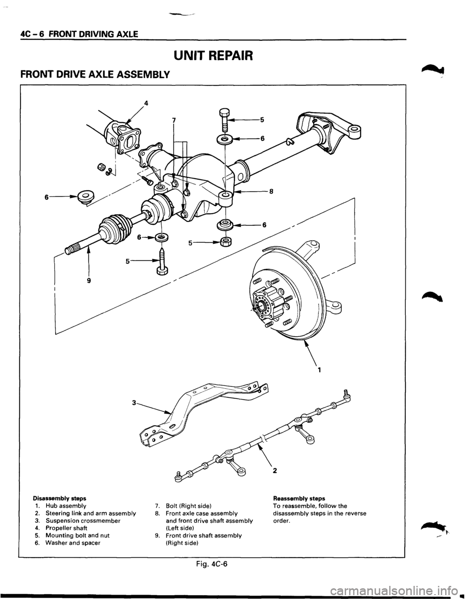
4C-6 FRONT DRIVING AXLE
UNIT REPAIR
FRONT DRIVE AXLE ASSEMBLY
9
3
Disassembly steps
1. Hub assembly 2. Steering link and arm assembly 3. Suspension crossmember 4. Propeller shaft 5. Mounting bolt and nut 6. Washer and spacer
4
7. Bolt (Right side)
8. Front axle case assembly and front drive shaft assembly (Left side) 9. Front drive shaft assembly (Right side)
Fig. 4C-6
I
j
1
Reassembly steps To reassemble, follow the disassembly steps in the reverse
order.
•
Page 285 of 1928
l•!•l DISASSEMBLY
•
•
•
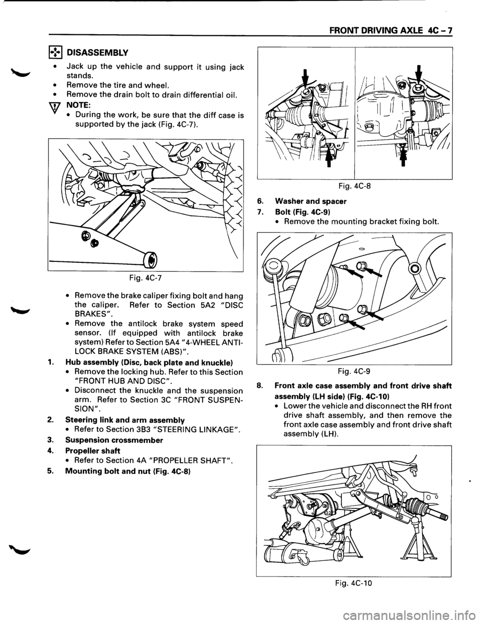
Jack up the vehicle and support it using jack
stands.
Remove the
tire and wheel.
Remove the drain bolt to drain differential oil.
NOTE:
•
During the work, be sure that the diff case is
supported by the jack (Fig. 4C-7).
Fig.
4C-7
• Remov: the brake caliper fixing bolt and hang
the caliper. Refer to Section 5A2 "DISC
BRAKES".
•
Remove the antilock brake system speed
sensor.
(If equipped with antilock brake
system) Refer
to Section 5A4 "4-WHEEL ANTI
LOCK
BRAKE SYSTEM (ABS)".
1. Hub assembly (Disc, back plate and knuckle)
• Remove the locking hub. Refer to this Section
"FRONT HUB AND DISC".
•
Disconnect the knuckle and the suspension
arm. Refer
to Section 3C "FRONT SUSPEN
SION".
2. Steering link and arm assembly
• Refer to Section 3B3 "STEERING LINKAGE".
3. Suspension crossmember
4. Propeller shaft
• Refer to Section 4A "PROPELLER SHAFT".
5. Mounting bolt and nut (Fig. 4C-8)
FRONT DRIVING AXLE 4C-7
Fig. 4C-8
6. Washer and spacer
7. Bolt (Fig. 4C-9)
• Remove the mounting bracket fixing bolt.
Fig. 4C-9
8. Front axle case assembly and front drive shaft
assembly (LH side) (Fig. 4C-10)
• Lower the vehicle and disconnect the RH front
drive shaft assembly, and then remove the
front axle case assembly and front drive shaft
assembly (LH).
Fig. 4C-10
Page 286 of 1928
4C - 8 FRONT DRIVING AXLE
9. Front drive shaft assembly (RH)
l•!•l REASSEMBLY
9. Front drive shaft assembly (RH)
• Lay the assembly on the lower arm.
8. Front axle case assembly and front drive shaft
assembly (LH)
• Place the axle case on the jack, connect to the
front drive shaft assembly (RH) before
installing to the vehicle.
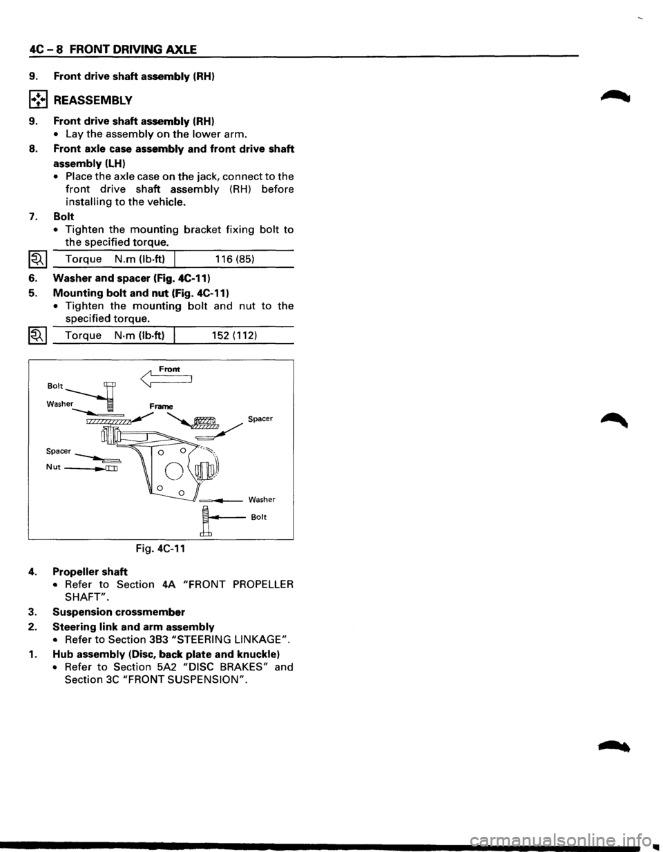
7. Bolt
• Tighten the mounting bracket fixing bolt to
the specified torque.
~~~ Torque N.m (lb.ft) I 116 (85)
6. Washer and spacer (Fig. 4C-11)
5. Mounting bolt and nut (Fig. 4C-11)
• Tighten the mounting bolt and nut to the
specified torque.
~~~ Torque N·m (lb.ft) I 152 (112)
< From
=---Washer
A--Bolt
Fig. 4C-11
4. Propeller shaft
• Refer to Section 4A "FRONT PROPELLER
SHAFT".
3. Suspension crossmember
2. Steering link and arm assembly
• Refer to Section 383 "STEERING LINKAGE".
1. Hub assembly (Disc, back plate and knuckle)
• Refer to Section 5A2 "DISC BRAKES" and
Section
3C "FRONT SUSPENSION".
Page 578 of 1928
·,'
6A1-20 ENGINE (V6 3.2L DOHC AND SOHC)
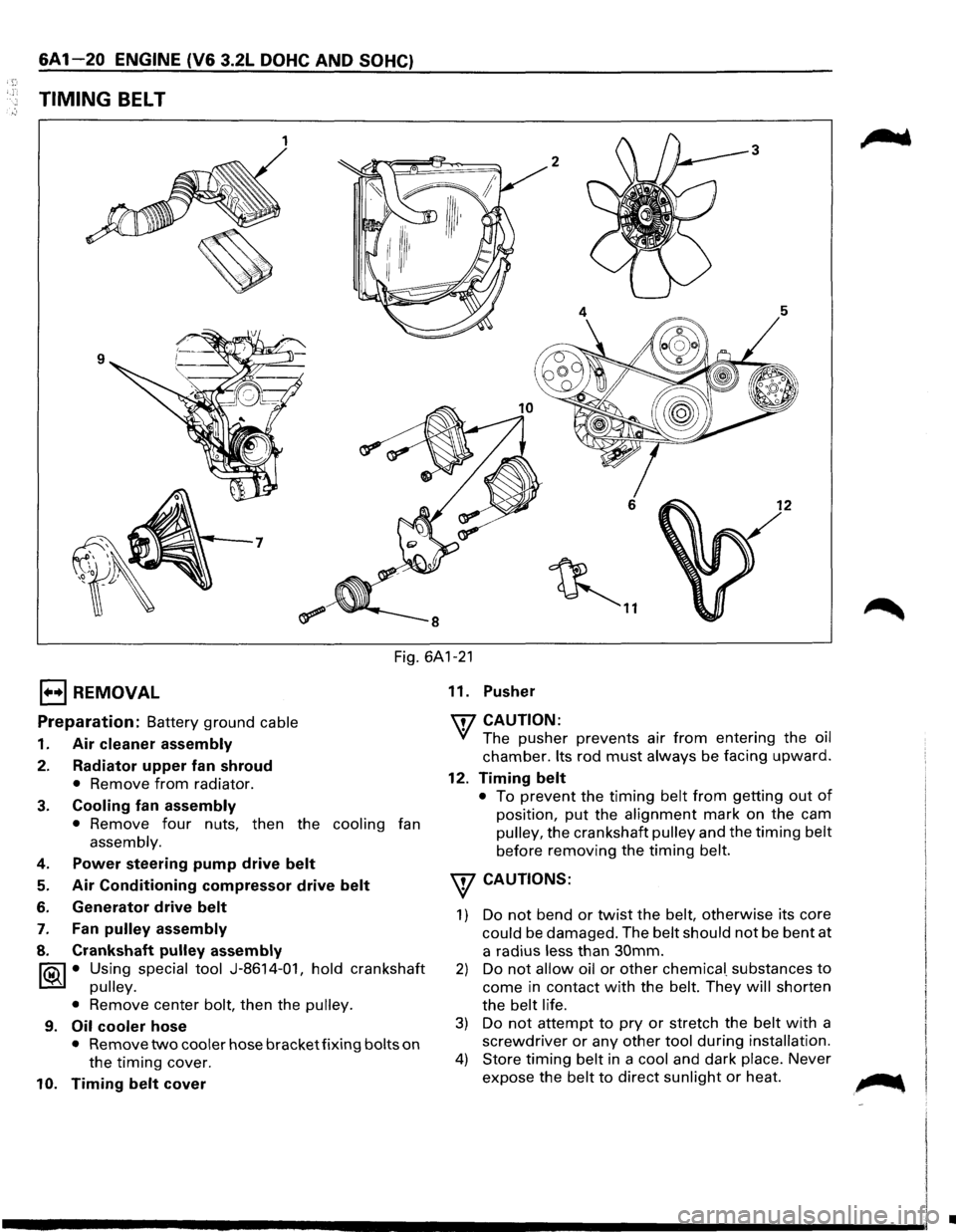
TIMING BELT
1 3
2
6 12
~ ..
Fig. 6A1-21
1••1 REMOVAL
Preparation: Battery ground cable
1. Air cleaner assembly
2. Radiator upper fan shroud
• Remove from radiator.
3. Cooling fan assembly
• Remove four nuts, then the cooling fan
assembly.
4. Power steering pump drive belt
5. Air Conditioning compressor drive belt
6. Generator drive belt
7. Fan pulley assembly
8. Crankshaft pulley assembly
~ • Using special tool J-8614-01, hold crankshaft
~ pulley.
•
Remove center bolt, then the pulley.
9. Oil cooler hose
• Remove two cooler hose bracket fixing bolts on
the timing cover.
10. Timing belt cover 11.
Pusher
'IT7 CAUTION:
'if The pusher prevents air from entering the oil
chamber. Its rod must always be facing upward.
12. Timing belt
• To prevent the timing belt from getting out of
position, put the alignment mark on the cam
pulley, the crankshaft pulley and the timing belt
before removing the timing belt.
w CAUTIONS:
1) Do not bend or twist the belt, otherwise its core
could be damaged. The belt should not be bent at
a radius
less than 30mm.
2) Do not allow oil or other chemica[ substances to
come in contact with the belt. They will shorten
the
belt life.
3) Do not attempt to pry or stretch the belt with a
screwdriver or any other tool during installation.
4) Store timing belt in a cool and dark place. Never
expose the
belt to direct sunlight or heat. ~
•
Page 581 of 1928
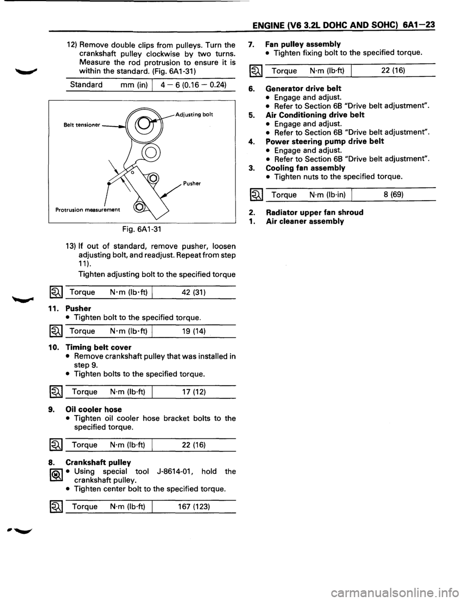
12) Remove double clips from pulleys. Turn the
crankshaft
pulley clockwise by two turns.
Measure the rod protrusion to ensure
it is
within the standard. (Fig. 6A 1-31)
Standard
mm (in) I 4 - 6 (0.16 -0.24)
Adjusting bolt
Pusher
Fig. 6A1-31
13) If out of standard, remove pusher, loosen
adjusting bolt, and readjust. Repeat from step
11 ).
Tighten adjusting bolt to the specified torque
1~1 Torque N·m (lb·ft) I 42 (31)
11. Pusher
• Tighten bolt to the specified torque.
1~1 Torque N·m (lb·ft) I 19 (14)
10. Timing belt cover
• Remove crankshaft pulley that was installed in
step
9.
• Tighten bolts to the specified torque.
~~~ Torque N·m (lb·ft) I 17 (12)
9. Oil cooler hose
• Tighten oil cooler hose bracket bolts to the
specified torque.
~~~ Torque N·m (lb·ft) I 22 (16)
8. Crankshaft pulley
l"iQ\1 • Using special tool J-8614-01, hold the
~ crankshaft pulley.
•
Tighten center bolt to the specified torque.
1~1 Torque N·m (lb·ft) 167 (123)
ENGINE (V6 3.2L DOHC AND SOHC) 6A1-23
7. Fan pulley assembly
• Tighten fixing bolt to the specified torque.
~~~ Torque N·m (lb·ft) 22 (16)
6. Generator drive belt
• Engage and adjust.
• Refer to Section 68 "Drive belt adjustment".
5. Air Conditioning drive belt
• Engage and adjust.
• Refer to Section 68 "Drive belt adjustment".
4. Power steering pump drive belt
• Engage and adjust.
• Refer to Section 68 "Drive belt adjustment".
3. Cooling fan assembly
• Tighten nuts to the specified torque.
~~~ Torque N·m (lb·in) I 8 (69)
2. Radiator upper fan shroud
1. Air cleaner assembly
Page 582 of 1928
, r;
6A 1-24 ENGINE (V6 3.2L DOHC AND SOHC)
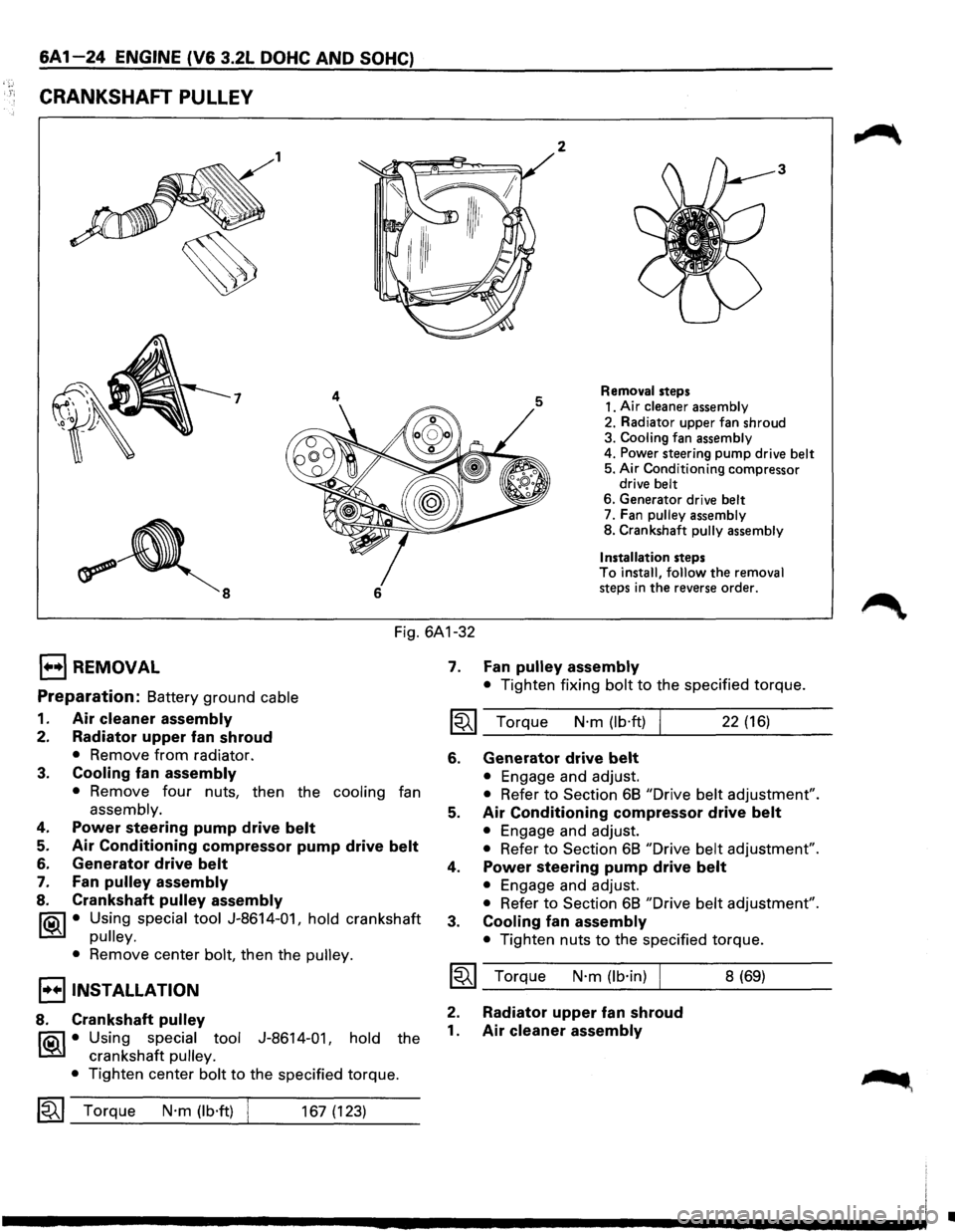
CRANKSHAFT PULLEY
1 2
7 4
6
3
Removal steps
1. Air
cleaner assembly
2. Radiator upper fan shroud
3. Cooling fan assembly
4. Power steering pump drive belt 5. Air Conditioning compressor
drive belt
6. Generator drive belt 7. Fan pulley assembly
8. Crankshaft pully assembly
Installation
steps To install, follow the removal steps in the reverse order.
Fig. 6A1-32
E) REMOVAL
Preparation: Battery ground cable
1. Air cleaner assembly
2. Radiator upper fan shroud
• Remove from radiator.
3. Cooling fan assembly
• Remove four nuts, then the cooling fan
assembly.
4. Power steering pump drive belt
5. Air Conditioning compressor pump drive belt
6. Generator drive belt
7. Fan pulley assembly
8. Crankshaft pulley assembly
IQil • Using special tool J-8614-01, hold crankshaft
I.:Sil pulley.
•
Remove center bolt, then the pulley.
I••IINSTALLATION
8. Crankshaft pulley
IQil • Using special tool J-8614-01, hold the
I.:Sil crankshaft pulley.
•
Tighten center bolt to the specified torque.
1~1 Torque N·m (lb·ft) 167 (123)
7. Fan pulley assembly
• Tighten fixing bolt to the specified torque.
1~1 Torque N·m (lb·ft) 22 (16)
6. Generator drive belt
• Engage and adjust.
• Refer to Section 68 "Drive belt adjustment".
5. Air Conditioning compressor drive belt
• Engage and adjust.
• Refer to Section 68 "Drive belt adjustment".
4. Power steering pump drive belt
• Engage and adjust.
• Refer to Section 68 "Drive belt adjustment".
3. Cooling fan assembly
• Tighten nuts to the specified torque.
~~~ Torque N·m (lb·in) I
2. Radiator upper fan shroud
1. Air cleaner assembly
8 (69)
•
Page 584 of 1928
6A1-26 ENGINE (V& 3.2L DOHC AND SOHC)
1••1 REMOVAL
Preparation: Battery ground cable
1. Air cleaner assembly
2. Radiator upper fan shroud
• Remove from radiator.
3. Cooling fan assembly
• Remove four nuts, then the cooling fan
assembly.
4. Accelerator Pedal cable
• Disconnect from throttle body and cable
bracket.
5. Vacuum booster hose
• Disconnect from common chamber.
6. Connectors
• Disconnect from Manifold Absolute Pressure,
canister Vacuum Switching Valve (VSV),
Exhaust
Gas Recirculation VSV, Intake Air
Temperature and ground cable.
7. High tension cables
• Disconnect from cylinder head cover.
8. Ignition Control Module assembly
• Disconnect three Electronic Ignition con
nectors.
• Remove three Electronic Ignition bracket fixing
bolts, and remove Electronic
Ignition assembly
with high tension cables.
9. Throttle body
• Remove four fixing bolts.
10. Vacuum hoses
• Disconnect vacuum hoses on canister VSV and
Exhaust Gas Recirculation
VSV from the
throttle body.
11. Positive Crankcase Ventilation hose
• Disconnect from common chamber.
12. Fuel Pressure Control Valve vacuum hose
• Disconnect from common chamber.
13. Evaporative Emission Canister Purge hose
• Disconnect from common chamber.
14. Exhaust Gas Recirculation Valve assembly
• Remove five bolts from common chamber,
exhaust manifold and cylinder head cover.
15. Common chamber
• Remove six bolts, two nuts and three bracket
fixing bolts, then remove the
common
chamber.
16. Fuelhoses
• Disconnect feed and return fuel hoses from fuel
pipes, and remove
two bracket fixing bolts on
the cylinder head cover.
17. Power steering pump drive belt
18. Air Conditioning compressor drive belt
19. Generator drive belt
20. Power steering pump
21. Fan pulley assembly
22. Crankshaft pulley assembly
lf5\l • Using special tool J-8614-01, hold crankshaft
t:::!il pulley.
•
Remove center bolt, then the pulley.
23. Oil cooler hose
• Remove two cooler hose bracket fixing bolts on
the timing belt cover.
24. Timing belt cover
25. Pusher
CAUTION:
The pusher prevents air from entering the oil chamber.
Its rod must always be facing upward.
26. Timing belt
CAUTIONS:
1) Do not bend or twist the belt, otherwise its core
could
be damaged. The belt should not be bent at
a radius less than 30mm.
2) Do not allow oil or other chemical substances to
come in contact with the belt. They will shorten
the belt life.
3) Do not attempt to pry or stretch the belt with a
screwdriver
or any other tool during installation.
4) Store timing belt in a cool and dark place. Never
expose the belt
to direct sunlight or heat.
27. Cylinder head cover
• Remove 11 fixing bolts, then the cylinder head
cover.
28. Camshaft
• Camshaft pulley fixing bolt and camshaft pulley
•
Front plate fixing bolts and front plate
• Camshaft bracket fixing bolts and camshaft
29. Rocker arm
• Fixing bolts and rocker arm
I••! INSTALLATION
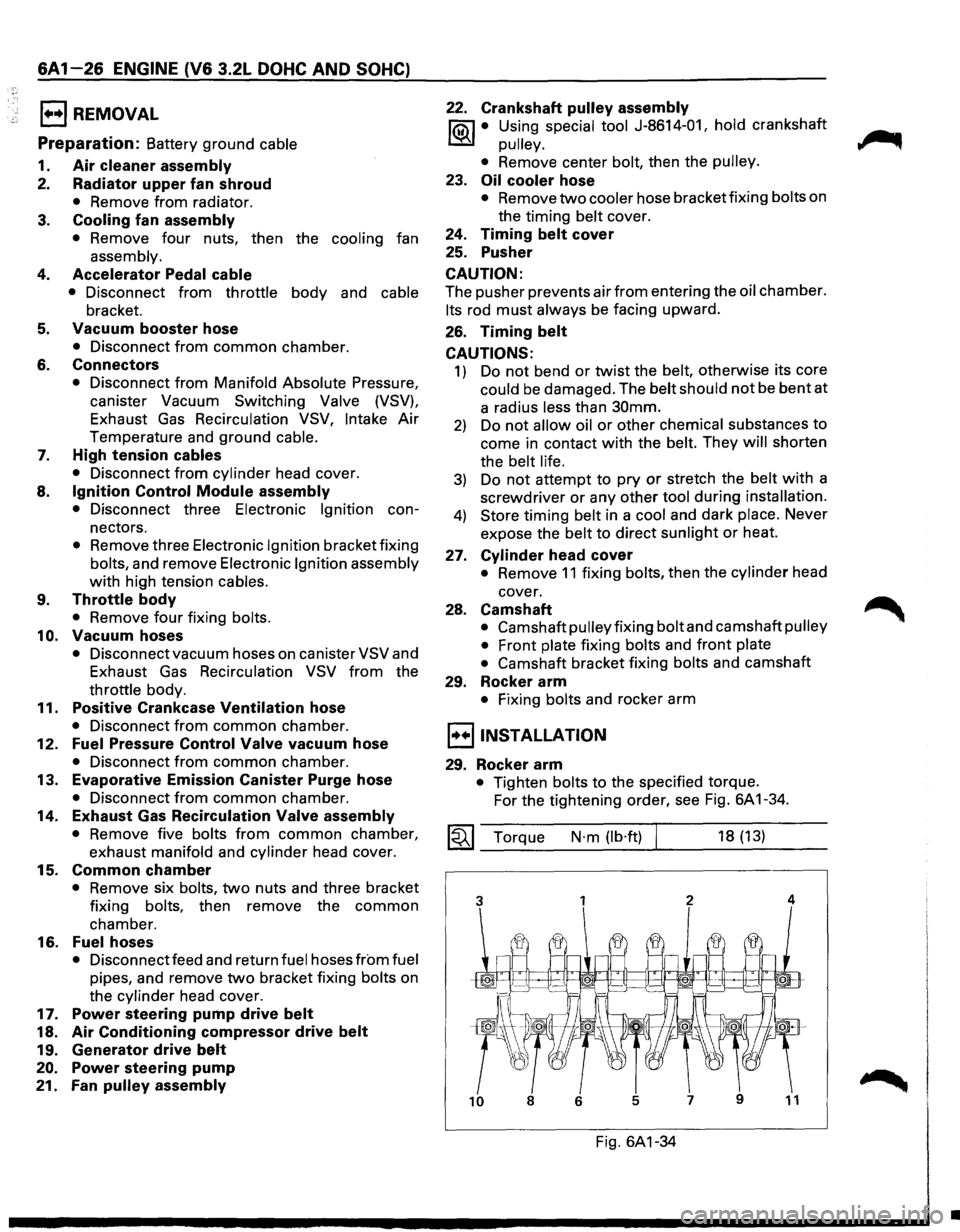
29. Rocker arm
• Tighten bolts to the specified torque.
For the tightening order, see Fig. 6A 1-34.
~~~ Torque N·m (lb·ft) 18 (13)
Fig. 6A1-34
•
Page 586 of 1928
If! (;
6A 1-28 ENGINE (V6 3.2L DOHC AND SOHC)
21. Fan pulley assembly
• Tighten fixing bolt to the specified torque.
~ Torque N·m (lb·ft) I 22 (16)
20.
Power steering pump
• Tighten pump fixing bolts to the specified
torque.
~ Torque N·m (lb·ft) 56 (41)
19. Generator drive belt
• Engage and adjust.
• Refer to Section 68 "Drive belt adjustment".
18. Air Conditioning compressor drive belt
• Engage and adjust.
• Refer to Section 68 "Drive belt adjustment".
17. Power steering pump drive belt
• Engage and adjust.
• Refer to Section 68 "Drive belt adjustment".
16. Fuelhoses
• Connect surely the hoses and install the bolts
on the head cover.
15. Common chamber
• Tighten bolts and nuts to the specified torque.
Bolts
~~~ Torque N·m (lb·ft) 24 (17)
Nuts
~~~ Torque N·m (lb·ft) 24 (17)
14. Exhaust Gas Recirculation Valve assembly
• Tighten bolts to the specified torque.
Exhaust Gas
Recirculation Valve Side
~~~ Torque N·m (lb·in) I 8 (69)
Exhaust Manifold Side
~~~ Torque N·m (lb·ft) 28 (21)
13. Evaporative Emission Canister Purge hose
12.
Fuel Pressure Control Valve vacuum hose
11. Positive
Crankcase Ventilation hose
9. Throttle body
• Tighten bolts to the specified torque.
~~~ Torque N·m (lb·ft) I 19 (14)
10. Vacuum hoses
• Connect vacuum hoses on canister Vacuum
Switching
Valve and Exhaust Gas Recirculation
Vacuum Switching Valve to the throttle body.
8. Ignition Control Module assembly
• Tighten bolts to the specified torque and
connect connector.
~~~ Torque N·m (lb·ft) 19 (14)
7.
6.
5.
4.
High tension cables
Connectors
• Connect each connector carefully.
Vacuum booster hose
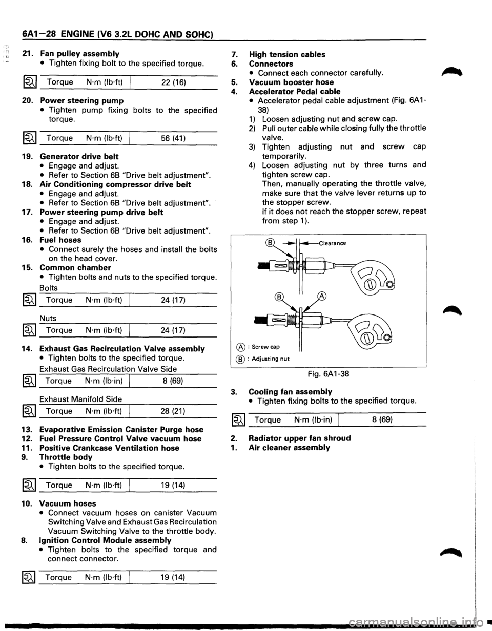
Accelerator Pedal cable
• Accelerator pedal cable adjustment (Fig. 6A 1-
38)
1) Loosen adjusting nut and screw cap.
2) Pull outer cable while closing fully the throttle
valve.
3) Tighten adjusting nut and screw cap
temporarily.
4) Loosen adjusting nut by three turns and
tighten screw cap.
Then,
manually operating the throttle valve,
make sure that the valve lever returns up to
the stopper screw.
If it does not reach the stopper screw, repeat
from step 1 ) .
@:Screw cap
@ :Adjusting nut
Fig. 6A1-38
3. Cooling fan assembly
• Tighten fixing bolts to the specified torque.
~~~ Torque N·m (lb·in) I 8 (69)
2. Radiator upper fan shroud
1. Air
cleaner assembly
•