lock ISUZU TROOPER 1995 Workshop Manual
[x] Cancel search | Manufacturer: ISUZU, Model Year: 1995, Model line: TROOPER, Model: ISUZU TROOPER 1995Pages: 1928
Page 1432 of 1928
8-242 CHASSIS ELECTRICAL
STARTER SWITCH
Refer to "START AND CHARGING" of this section.
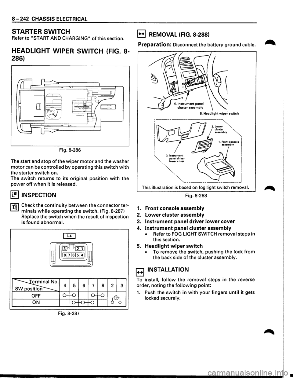
HEADLIGHT WIPER SWITCH (FIG. 8-
286)
Fig. 8-286
The start and stop
of the wiper motor and the washer
motor can be controlled by operating this switch with
the starter switch on.
The switch returns to its
original position with the
power off when it is released.
(1!] INSPECTION
rfiil Check the continuity between the connector ter
L:::.I minals while operating the switch. (Fig. 8-287)
Replace the switch when the result of inspection
is
found abnormal.
[ill
[I
roo8___8tillJ1
lsl7lslsi4IJ ill
' )
~· s 4 5 6 7 8 2 1 3
OFF o--o o-f-o
~ ON o-f-0--f-0
Fig. 8-287
B REMOVAL (FIG. 8-288)
Preparation: Disconnect the battery ground cable. ~
This illustration is based on fog light switch removal.
Fig. 8-288
1.
Front console assembly
2. Lower cluster assembly
3. Instrument panel driver lower cover
4. Instrument panel cluster assembly
• Refer to FOG LIGHT SWITCH removal steps in
this section.
5.
Headlight wiper switch
• To remove the switch, pushing the lock from
the back side of the cluster assembly.
B INSTALLATION
To install, follow the removal steps in the reverse
order, noting the
following point:
1. Push the switch in with your fingers until it gets
locked securely.
•
Page 1436 of 1928
8-246 CHASSIS ELECTRICAL
AUDIO, AUTO ANTENNA, CIGARETTE LIGHTER AND DIGITAL CLOCK
GENERAL DESCRIPTION
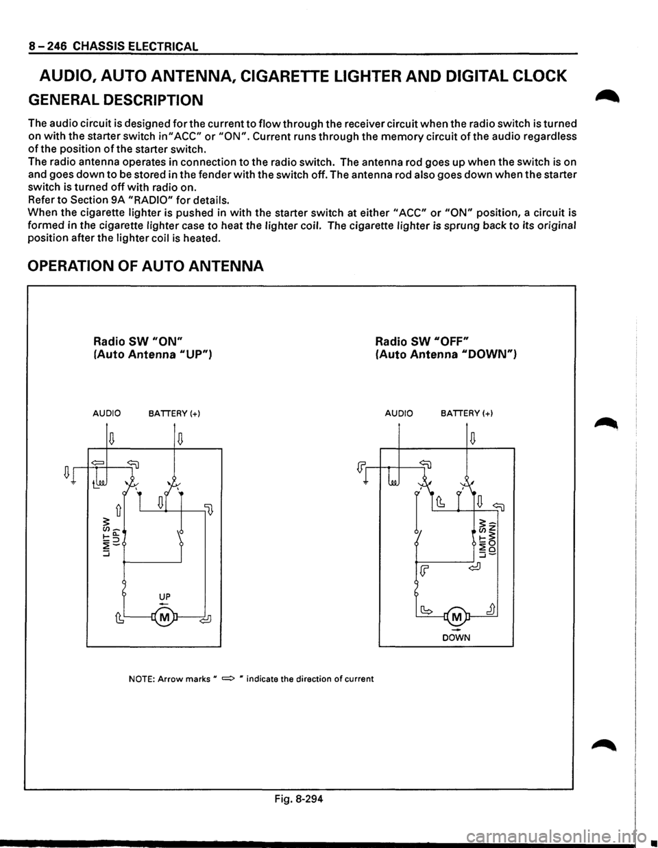
The audio circuit is designed for the current to flow through the receiver circuit when the radio switch is turned
on
with the starter switch in" ACC" or "ON". Current runs through the memory circuit of the audio regardless
of the position of the starter switch.
The radio antenna operates in connection
to the radio switch. The antenna rod goes up when the switch is on
and goes
down to be stored in the fender with the switch off. The antenna rod also goes down when the starter
switch is turned
off with radio on.
Refer
to Section 9A "RADIO" for details.
When the cigarette lighter is pushed in
with the starter switch at either "ACC" or "ON" position, a circuit is
formed in the cigarette lighter case
to heat the lighter coil. The cigarette lighter is sprung back to its original
position after the lighter coil
is heated.
OPERATION OF AUTO ANTENNA
Radio SW "ON"
(Auto Antenna "UP")
AUDIO BATTERY(+)
NOTE: Arrow marks u =:> " indicate the direction of current
Fig. 8-294
Radio SW "OFF"
(Auto Antenna "DOWN")
AUDIO BATTERY(+)
M
DOWN
•
Page 1441 of 1928
AUDIO
AUTO ANTENNA
Refer to Section 9A "RADIO" for details.
CIGARETTE LIGHTER
~ INSPECTION
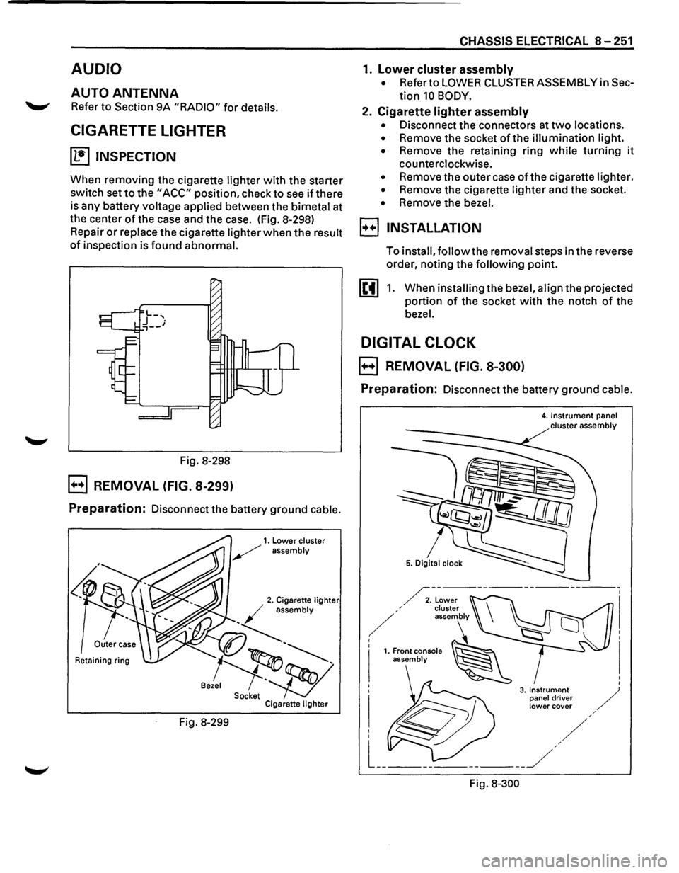
When removing the cigarette lighter with the starter
switch set
to the "ACC" position, check to see if there
is any battery voltage applied between the bimetal at
the center
of the case and the case. (Fig. 8-298)
Repair
or replace the cigarette lighter when the result
of inspection is found abnormal.
Fig. 8-298
B REMOVAL (FIG. 8-299)
Preparation: Disconnect the battery ground cable.
Retaining ring
Fig. 8-299
CHASSIS ELECTRICAL 8-251
1. lower cluster assembly
• Refer to LOWER CLUSTER ASSEMBLY in Sec
tion 10 BODY.
2. Cigarette lighter assembly
• Disconnect the connectors at two locations.
• Remove the socket of the illumination light.
•
Remove the retaining ring while turning it
counterclockwise.
• Remove the outer case of the cigarette lighter.
• Remove the cigarette lighter and the socket.
• Remove the bezel.
I••! INSTALLATION
To install, follow the removal steps in the reverse
order, noting the
following point.
1. When installing the bezel, align the projected
portion
of the socket with the notch of the
bezel.
DIGITAL CLOCK
B REMOVAL (FIG. 8-300)
Preparation: Disconnect the battery ground cable.
Fig.
8-300
4. Instrument panel cluster assembly
Page 1442 of 1928
8-252 CHASSIS ELECTRICAL
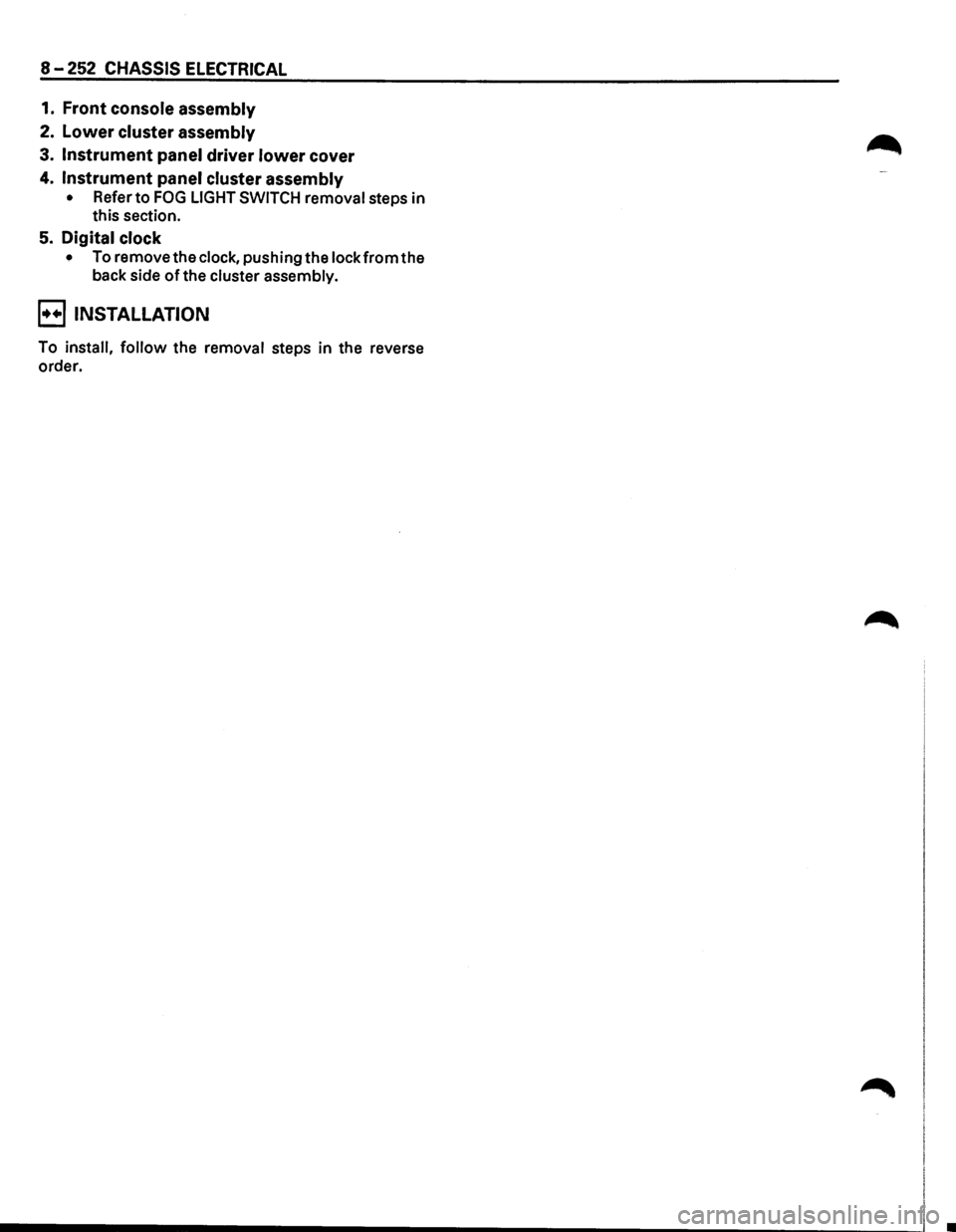
1. Front console assembly
2. Lower cluster assembly
3. Instrument panel driver lower cover
4. Instrument panel cluster assembly
• Refer to FOG LIGHT SWITCH removal steps in
this section.
5. Digital clock
• To remove the clock, pushing the lock from the
back side
of the cluster assembly.
E) INSTALLATION
To install, follow the removal steps in the reverse
order.
Page 1457 of 1928
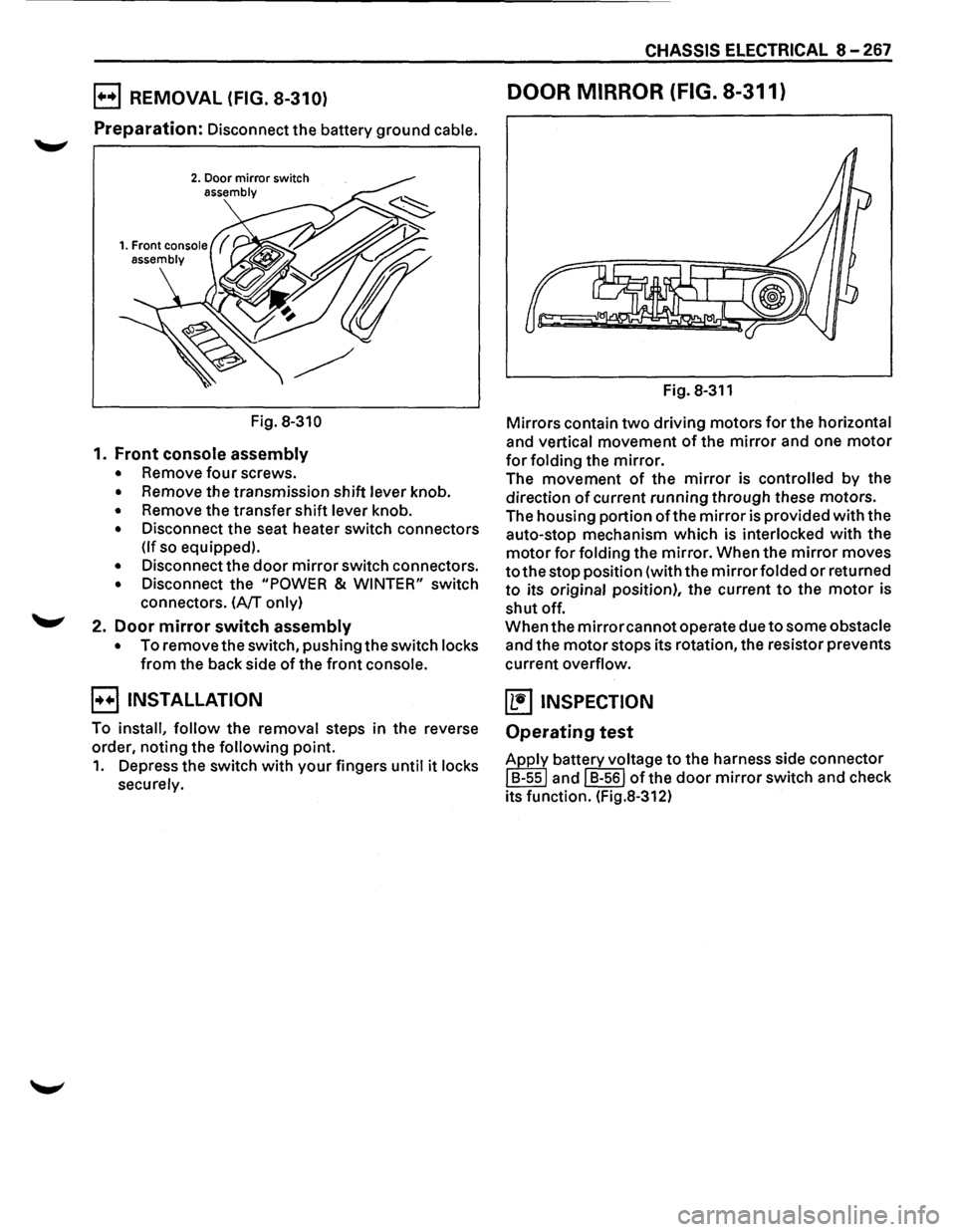
E) REMOVAL (FIG. 8-310)
Preparation: Disconnect the battery ground cable.
2. Door mirror switch assembly
Fig. 8-310
1. Front console assembly
• Remove four screws.
• Remove the transmission shift lever knob.
• Remove the transfer shift lever knob.
• Disconnect the seat heater switch connectors
(If so equipped).
• Disconnect the door mirror switch connectors.
• Disconnect the "POWER & WINTER" switch
connectors.
(A/T only)
2. Door mirror switch assembly
• To remove the switch, pushing the switch locks
from the back side of the front console.
B INSTALLATION
To install, follow the removal steps in the reverse
order, noting the
following point.
1. Depress the switch with your fingers until it locks
securely.
CHASSIS ELECTRICAL 8-267
DOOR MIRROR (FIG. 8-311)
Fig. 8-311
Mirrors contain two driving motors for the horizontal
and vertical movement of the mirror and one motor
for folding the mirror.
The movement of the mirror is controlled by the
direction
of current running through these motors.
The housing portion
ofthe mirror is provided with the
auto-stop mechanism which is
interlocked with the
motor for folding the mirror. When the mirror moves
to the stop position (with the mirror folded or returned
to its original position), the current to the motor is
shut off.
When the
mirror cannot operate due to some obstacle
and the motor stops its rotation, the resistor prevents
current
overflow.
~ INSPECTION
Operating test
Apply battery voltage to the harness side connector
I B-ssl and I B-561 of the door mirror switch and check
its function. (Fig.8-312)
Page 1460 of 1928
8-270 CHASSIS ELECTRICAL
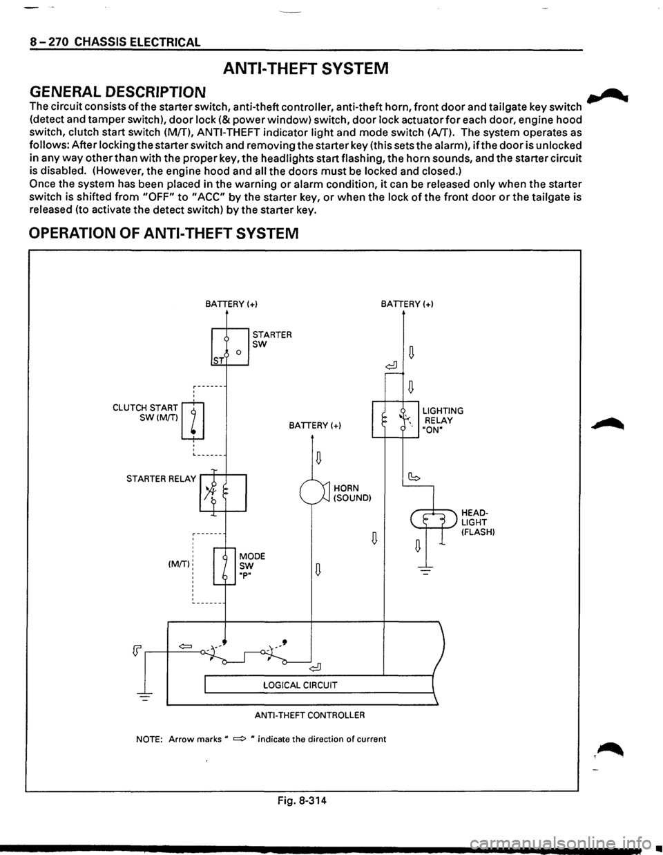
ANTI-THEFT SYSTEM
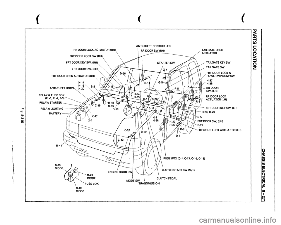
GENERAL DESCRIPTION .......
The circuit consists ofthe starter switch, anti-theft controller, anti-theft horn, front door and tailgate key switch
(detect and tamper switch),
door lock (&power window) switch, door lock actuator for each door, engine hood
switch, clutch start switch (MfT),
ANTI-THEFT indicator light and mode switch (AfT). The system operates as
follows: After locking the starter switch and removing the starter key (this sets the alarm),
ifthe door is unlocked
in any
way other than with the proper key, the headlights start flashing, the horn sounds, and the starter circuit
is disabled. (However,
the engine hood and all the doors must be locked and closed.)
Once the system has been placed in the warning or alarm condition, it can be released only when the starter
switch is shifted
from "OFF" to "ACC" by the starter key, or when the lock of the front door or the tailgate is
released (to activate the detect switch)
by the starter key.
OPERATION OF ANTI-THEFT SYSTEM
'
'
CLUTCH START m
SW(M/Tiw
' '
'
BATIERY(+)
0 ST
STARTER sw
BATIERY(+)
L------
STARTER RELAY
' ' (MIT):
'
'
'
HORN
(SOUND)
ANTI-THEFT CONTROLLER
BATIERY(+)
LIGHTING
RELAY
"ON"
HEADLIGHT (FLASH)
NOTE: Arrow marks u ~ u indicate the direction of current
Fig. 8-314
•
Page 1461 of 1928
'"T1 !fl' co I w _. (11
I i i, ~
(
RR
DOOR
LOCK
ACTUATOR
{RHJ
FRT
DOOR
LOCK
SW
(RH
FRT
DOOR
KEY
SW,
(RH),
( ANTI-THEFT
CONTROLLER
RR
DOOR
SW
(RHJ
-------
FRT
DOOR
SW,
(RH)
.~""··
\
/;'~
~
"'··
FRT
DOOR
LOCK
ACTUATOR
(RH)
'-, ..,/j.
',
H-14
'L
y'JIJ.
"·,
H-15"
82
ANTI-THEFT
HORN~-20
"-,
-
RELAY
& FUSE
BOX
~
{FL-1,
FL-2,
F-3)
~
RELAY:
STARTER BATTERY
X::
H-41 B-39 DIODE
B-40 DIODE
B-43 DIODE FUSE
BOX MODESW
TRANSMISSION ,
TAILGATE
LOCK
ACTUATOR
TAILGATE
KEY
SW
TAILGATESW
FRT
DOOR
LOCK
&
/'POWER
WINDOW
SW
H-37 H-38 RRDOOR SW,(LH)
.
RR
DOOR
LOCK
-~ACTUATOR
{LHJ
FRT
DOOR
KEY
SW,
{LH)
-H-28,
H-29
FRT
DOOR
LOCK
ACTUA
TOR
(LH)
(
;g ~ C/) 5 C') ~ 0 z
n :X: ~ (/) 0 m rm ~ n ):a r-0) I N ..... -
Page 1462 of 1928
8-:-272 CHASSIS ELECTRICAL
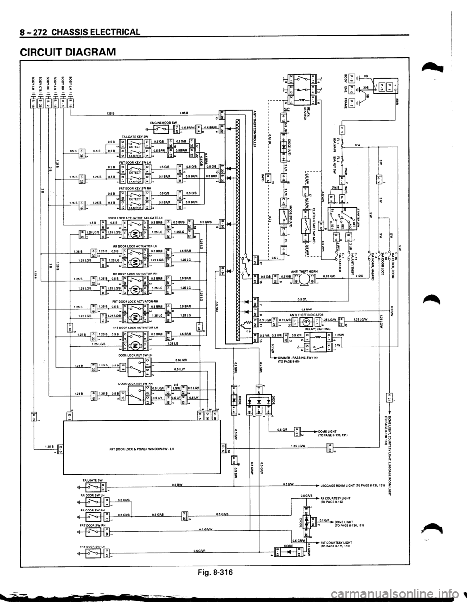
CIRCUIT DIAGRAM
3 3
3 3 3 3 !1 !1
!1 !1
!1 '< '< ~ ~ '< ;:: "' =-=-=-=-
=-
1.258 O.Rti8
5W
tl ~ ~ '" ,----.~ :j ' ~ ~1 :~
~'
~
g ~ ~ ~ ~ -~ ,p 1.258 .~
~~ ---~= ~= in ~~ >w i5 r ~ tl z g ~ .! .. ~ ?' ~ ~ ~ 1! .. 0.85G'O ~ 2 G'O 0 U!iB 1'1 1:
1.25LG/W
0.6LGIR 1.258 0.5LLIV
l.l!iB
1.258 FRT DOOR LOCK&. POWER WINDOW SW -LH 1.25LGIW
~ -~ c
~ 8 II-----------_!!,!!..!!!!..._ ________ .__-+-+---~!.ML---•LUGGAGEROOMUGHTITOPA.GE8130,13U i:
Fig.
8-316
~----
•
~_:;::_;:= ... RR COURTESV LIGHT ITO PAGE&-1301
DOME LIGHT ITOPAGES-130,1311
~
,
Page 1465 of 1928
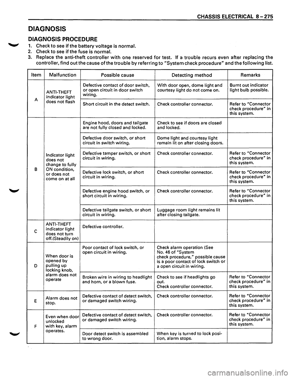
DIAGNOSIS
DIAGNOSIS PROCEDURE
.......,. 1. Check to see ifthe battery voltage is normal.
2. Check to see if the fuse is normal.
CHASSIS ELECTRICAL 8 -275
3. Replace the anti-theft controller with one reserved for test. If a trouble recurs even after replacing the
controller, find
out the cause of the trouble by referring to "System check procedure" and the following list.
Item Malfunction
Possible
cause Detecting method Remarks
Defective
contact of door switch,
With door open, dome light and Burnt
out indicator
ANTI-THEFT or open circuit in door switch courtesy light do not come on. light bulb possible.
indicator light wiring.
A does
not flash Short circuit in the detect switch.
Check controller connector. Refer to "Connector check procedure" in
this system.
Engine hood, doors and
tailgate Check to see if doors are closed are not fully closed and locked. and locked.
Defective door switch, or short Dome light and courtesy light circuit in switch wiring.
remain lit on after closing doors.
Indicator light Defective tamper switch, or short Check controller connector. Refer
to "Connector
does not circuit in wiring. check procedure" in
change to
fully this system.
B
ON condition, Defective lock switch, or short Check controller connector. Refer
to "Connector or does not come on at all circuit in wiring. check procedure" in
this system.
Defective engine hood switch, or Check
controller connector. Refer
to "Connector
short circuit in wiring. check
procedure" in
this system.
Defective
tailgate switch, or short Luggage room light remains lit circuit in wiring. after closing tailgate.
ANTI-THEFT
Defective controller.
c indicator light
does not turn off.(Steadily on) Poor contact
of lock switch, or Check alarm operation (See
When
door is open
circuit in wiring. No. 46 of "System
check procedure," possible cause
opened by
is a poor contact of lock switch or D pulling up
a open circuit in wiring. locking knob, alarm does not Broken wire in wiring to headlight Check to see if headlights go Refer
to "Connector operate
and horn, or a blown fuse. out. check procedure" in
Check
controller connector. this
system.
Alarm does not Defective contact of detect switch, Check controller connector.
Refer to "Connector
E
stop. or damaged switch wiring. check procedure" in
this system.
Even when
door Defective contact of detect switch, Check controller connector. Refer
to "Connector
unlocked
or damaged switch wiring. check procedure" in
F
with key, alarm this system.
operates. Door detect switch is
assembled When key is turned to lock posi-
to
wrong door. tion, alarm stops.
Page 1467 of 1928
------------- -
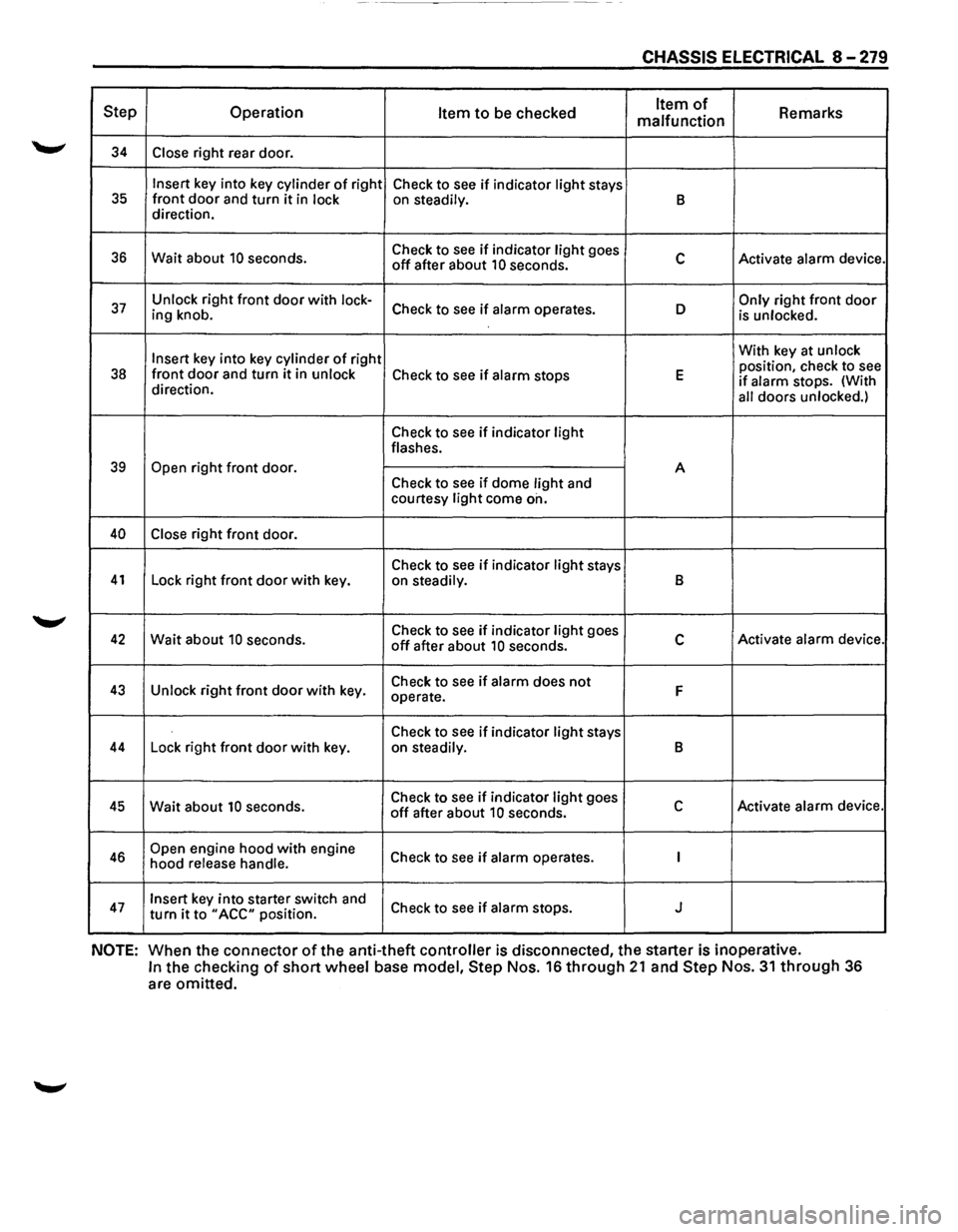
CHASSIS ELECTRICAL 8-279
Step Operation Item to be checked Item of Remarks
malfunction
34 Close right rear door.
Insert key into key cylinder of right
Check to see if indicator light stays 35 front door and turn it in lock on steadily. B direction.
36 Wait about 10 seconds. Check
to see if indicator light goes c Activate alarm device. off after about 10 seconds.
37 Unlock right front door with lock-Check to see if alarm operates. D Only right front door ing knob.
is unlocked.
Insert
key into key cylinder of right With
key at unlock
position, check to see 38 front door and turn it in unlock Check to see if alarm stops E if alarm stops. (With
direction.
all doors unlocked.)
Check to see if indicator light flashes.
39 Open right front door.
A
Check to
see if dome light and
courtesy light come on.
40 Close right front door.
Check to
see if indicator light stays 41 Lock right front door with key.
on steadily. B
42 Wait about 10 seconds. Check
to see if indicator light goes c Activate alarm device. off after about 10 seconds.
43 Unlock right front door with key. Check
to see if alarm does not F operate.
Check to
see if indicator light stays 44 Lock right front door with key.
on steadily. B
45 Wait about 10 seconds. Check
to see if indicator light goes c Activate alarm device. off after about 10 seconds.
46 Open engine hood with engine
Check to see if alarm operates. I hood release handle.
47 Insert key into starter switch and
Check to see if alarm stops. J turn it to "ACC" position.
NOTE: When the connector of the anti-theft controller is disconnected, the starter is inoperative.
In the checking of short wheel base model, Step Nos. 16 through 21 and Step Nos. 31 through 36
are omitted.