bulb ISUZU TROOPER 1995 Service Manual
[x] Cancel search | Manufacturer: ISUZU, Model Year: 1995, Model line: TROOPER, Model: ISUZU TROOPER 1995Pages: 1928
Page 1305 of 1928
•
•
•
•
CONTINUED FROM THE PREVIOUS PAGE
I
REPAIR A POOR CONNECTION AT THE CONNECTORS OR AN OPEN
CIRCUIT BElWEEN THE HARNESS SIDE CONNECTORS I IX-221 -I IX-141.
CHASSIS ELECTRICAL 8 -115
CONTINUED FROM THE PREVIOUS PAGE
REPAIR OR REPLACE THE SWITCH.
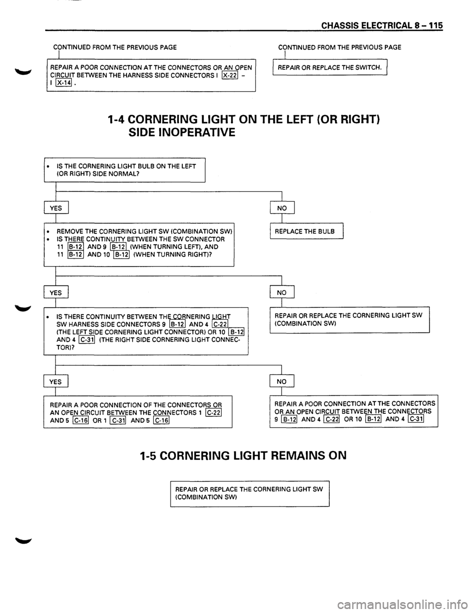
1-4 CORNERING LIGHT ON THE LEFT (OR RIGHT)
SIDE INOPERATIVE
IS THE CORNERING LIGHT BULB ON THE LEFT (OR RIGHT) SIDE NORMAL?
I
I
I
YES
I NO I
I I
REMOVE THE CORNERING LIGHT SW (COMBINATION SW) REPLACE THE BULB 1 IS THERE CONTINUITY BElWEEN THE SW CONNECTOR
11 ~B-121 AND 9 li-12j
1(WHEN
TURNING LEFT),
AND 11 B-12 AND 10 B-12 (WHEN TURNING RIGHT)?
I
I I
YES
I NO l
I I
IS
THERE CONTINUITY BElWEEN THE~NERING !LIGHT REPAIR OR REPLACE
THE CORNERING LIGHT SW
SW HARNESS SIDE CONNECTORS 9 B-12 AND 4 C-22 (COMBINATION
SW) (THE LEFT SIDE CORNERING LIGHT CONNECTOR) OR 10 I B-12j AND 4 j C-31j (THE RIGHT SIDE CORNERING LIGHT CONNEC-
TORI?
I
I I
YES
I NO I
I I
REPAIR A POOR CONNECTION OF THE CONNECTORS OR REPAIR A POOR CONNECTION AT THE CONNECTORS
AN OPEN CIRCUIT BElWEEN THE CONNECTORS 1 jC-22j OR AN OPEN CIRCUIT BElWEEN THE CONNECTORS
AND 5 IC-161 OR 1 I C-311 AND 5 IC-161 9 I B-121 AND 4 I C-221 OR 1 0 I B-121 AND 4 I C-311
1-5 CORNERING LIGHT REMAINS ON
REPAIR OR REPLACE THE CORNERING LIGHT SW
(COMBINATION SW)
Page 1307 of 1928
• •
CHASSIS ELECTRICAL 8 -117
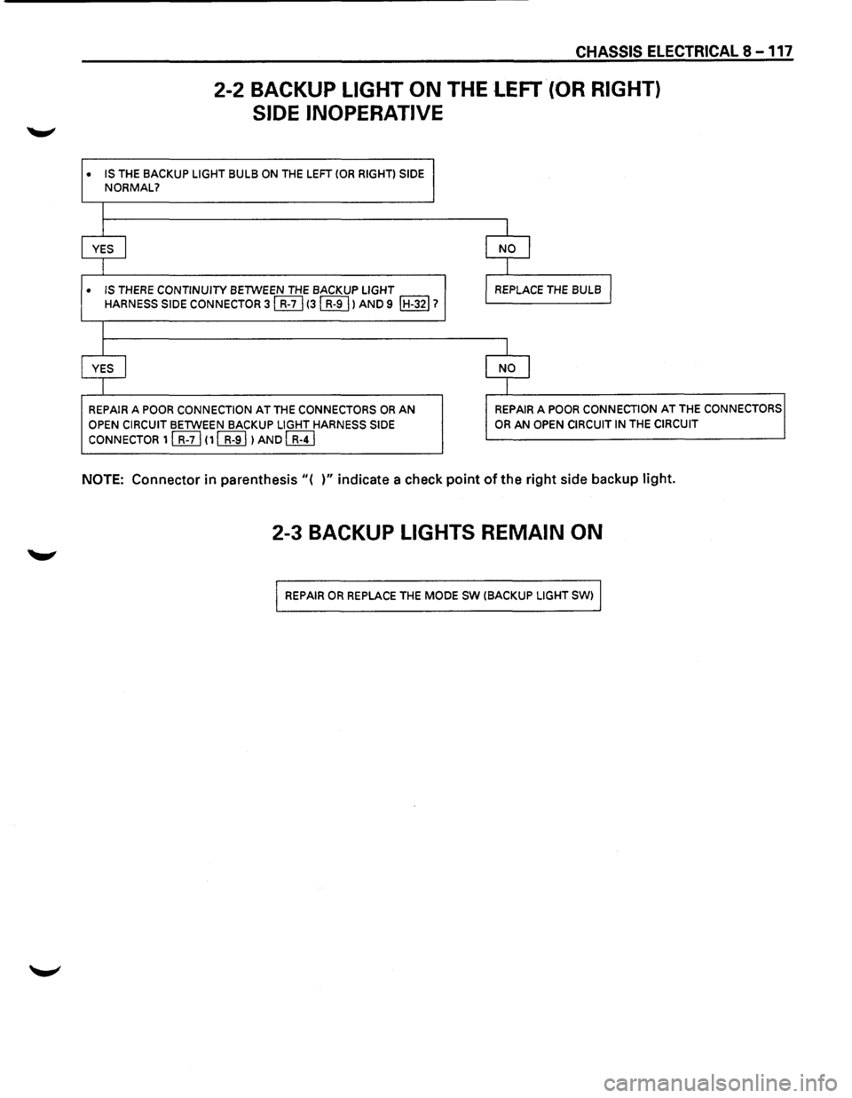
2-2 BACKUP LIGHT ON THE LEFT (OR RIGHT)
SIDE INOPERATIVE
IS THE BACKUP LIGHT BULB ON THE LEFT (OR RIGHT) SIDE NORMAL?
I
I I
YES I NO I
I I
IS THERE CONTINUITY BETWEEN THE BACKUP LIGHT REPLACE THE BULB J HARNESS SIDE CONNECTOR 3 §] (31 R-9 I) AND 9 IH-321?
I
I I
YES j NO I
I I
REPAIR A POOR CONNECTION AT THE CONNECTORS OR AN REPAIR A POOR CONNECTION AT THE CONNECTORS
OPEN CIRCUIT BETWEEN BACKUP LIGHT HARNESS SIDE OR AN OPEN CIRCUIT IN THE CIRCUIT
CONNECTOR 1 [friJ (1 ~)AND [R±J
NOTE: Connector in parenthesis "( )" indicate a check point of the right side backup light.
2-3 BACKUP LIGHTS REMAIN ON
REPAIR OR REPLACE THE MODE SW (BACKUP LIGHT SW)
Page 1311 of 1928
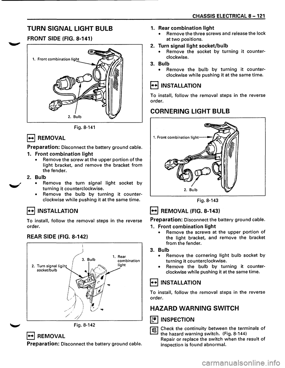
TURN SIGNAL LIGHT BULB
FRONT SIDE (FIG. 8-141)
Fig. 8-141
B REMOVAL
Preparation: Disconnect the battery ground cable.
1. Front combination light
• Remove the screw at the upper portion of the
light bracket, and remove the bracket from
the fender.
2. Bulb
• Remove the turn signal light socket by
turning it counterclockwise.
• Remove the bulb by turning it counter
clockwise
while pushing it at the same time.
B INSTALLATION
To install, follow the removal steps in the reverse
order.
REAR SIDE (FIG. 8-142)
~ Fig. 8-142
B REMOVAL
Preparation: Disconnect the battery ground cable.
CHASSIS ELECTRICAL 8-121
1. Rear combination light
• Remove the three screws and release the lock
at
two positions.
2. Turn signal light socket/bulb
• Remove the socket by turning it counter
clockwise.
3. Bulb
• Remove the bulb by turning it counter
clockwise
while pushing it at the same time.
B INSTALLATION
To install, follow the removal steps in the reverse
order.
CORNERING LIGHT BULB
Fig. 8-143
EJ REMOVAL (FIG. 8-143)
Preparation: Disconnect the battery ground cable.
1. Front combination light
• Remove the screws at the upper portion of
the light bracket, and remove the bracket
from the fender.
3. Bulb
• Remove the cornering light bulb socket by
turning it counterclockwise.
• Remove the bulb by turning it counter
clockwise while pushing it at the same time.
E) INSTALLATION
To install, follow the removal steps in the reverse
order.
HAZARD WARNING SWITCH
~ INSPECTION
rfll Check the continuity between the terminals of
~ the hazard warning switch. (Fig. 8-144)
Repair
or replace the switch when the result of
inspection is found abnormal.
Page 1312 of 1928
8-122 CHASSIS ELECTRICAL
rn
~~:::1
ill I -
~I . 4 s 6 7 8 2 1 3 n
ON o--o-f-0 0 -o
~ OFF o--o
Fig. 8-144
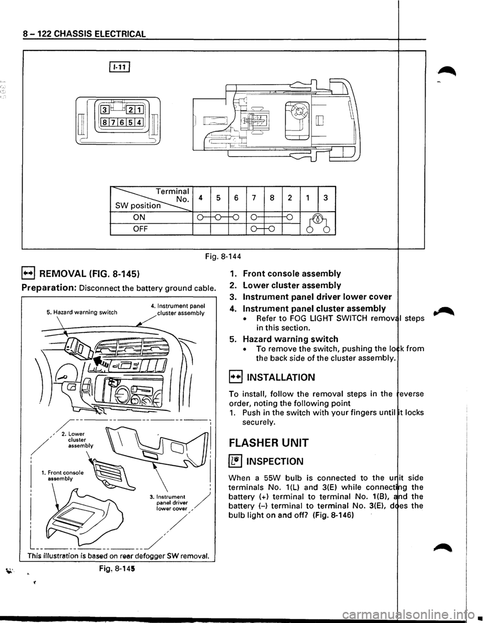
B REMOVAL (FIG. 8-145)
Preparation: Disconnect the battery ground cable.
5. Hazard warning switch 4. Instrument panel
cluster assembly
I
I
3. Instrument / panel driver lower cover ,
This illustration is based on re-ar defogger SW removal.
Fig, 8-145
'(
1. Front console assembly
2. Lower cluster assembly
3. Instrument panel driver lower cover
4. Instrument panel cluster assembly
• Refer to FOG LIGHT SWITCH remov I steps
in this section.
5. Hazard warning switch
• To remove the switch, pushing the lo k from
the back side of the cluster assembly.
B INSTALLATION
To install, follow the removal steps in the everse
order, noting the
following point
1. Push in the switch with your fingers until t locks
securely.
FLASHER UNIT
~ INSPECTION
When a SSW bulb is connected to the u it side
terminals No. 1(L) and 3(E) while connecti g the
battery
(+) terminal to terminal No. 1(8), nd the
battery (-)
terminal to terminal No. 3(E), d es the
bulb light on and off? (Fig. 8-146)
~
•
Page 1314 of 1928
8-124 CHASSIS ELECTRICAL
1. Backup light switch For low note (Fig.S-151)
• Remove the connectors.
• Remove the switch by turning it counter
clockwise.
B INSTALLATION
To install, follow the removal steps in the reverse
order,
noting the following point.
1.
Backup light switch
li:i1 • Apply liquid gasket to the screw portion of
~ the switch to prevent oil leak.
BACKUP LIGHT BULB
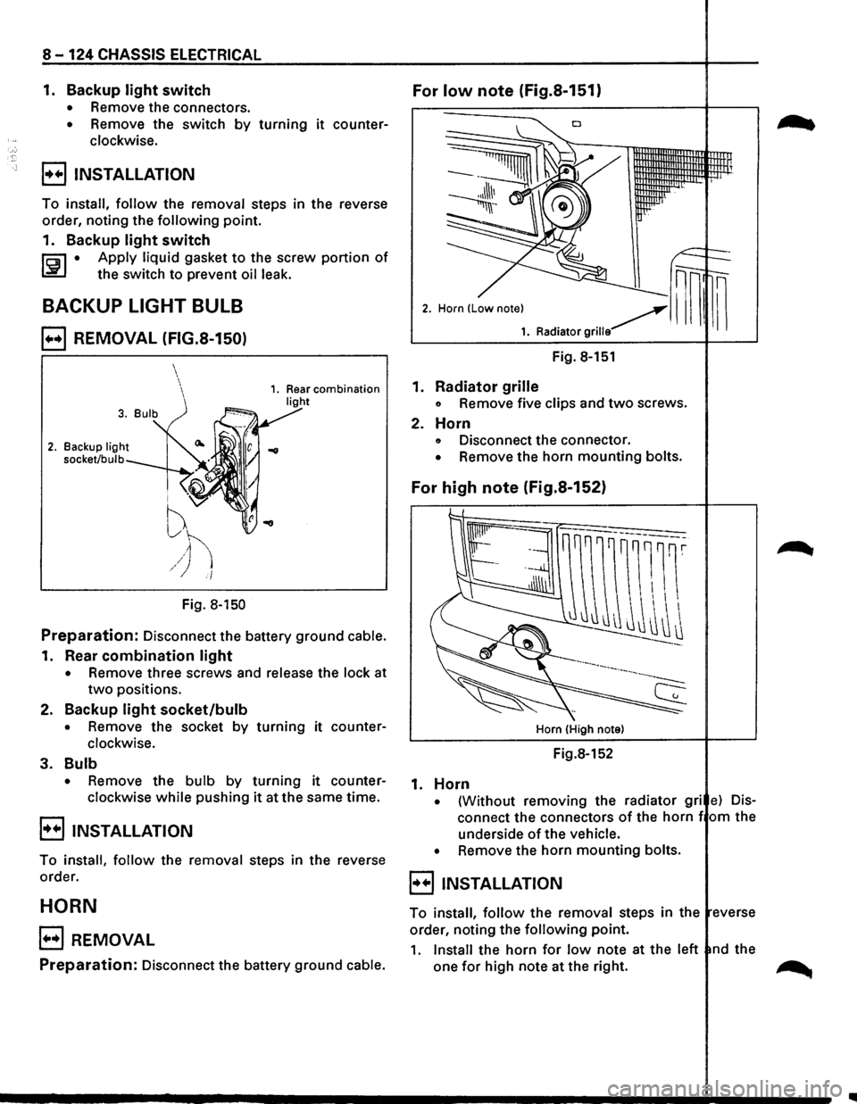
B REMOVAL (FIG.S-150)
2. Backup light
socket/bulb
i ''V
f
~h /) i/
Fig. 8-150
Preparation: Disconnect the battery ground cable.
1. Rear combination light
• Remove three screws and release the lock at
two positions.
2.
Backup light socket/bulb
• Remove the socket by turning it counter
clockwise.
3. Bulb
• Remove the bulb by turning it counter
clockwise
while pushing it at the same time.
B INSTALLATION
To install, follow the removal steps in the reverse
order.
HORN
B REMOVAL
Preparation: Disconnect the battery ground cable.
Fig. 8-151
1.
Radiator grille
o Remove five clips and two screws.
2. Horn
o Disconnect the connector.
• Remove the horn mounting bolts.
For high note (Fig.S-152)
Horn (High note)
Fig.8-152
1. Horn
• {Without removing the radiator gri e) Dis
connect the connectors of the horn f om the
underside
of the vehicle.
•
Remove the horn mounting bolts.
8 INSTALLATION
To install, follow the removal steps in the everse
order, noting the
following point.
1. Install the horn for low note at the left nd the
one
for high note at the right. ~
Page 1325 of 1928
EJ INSTALLATION
To install, follow the removal steps in the reverse
order.
DOME LIGHT BULB
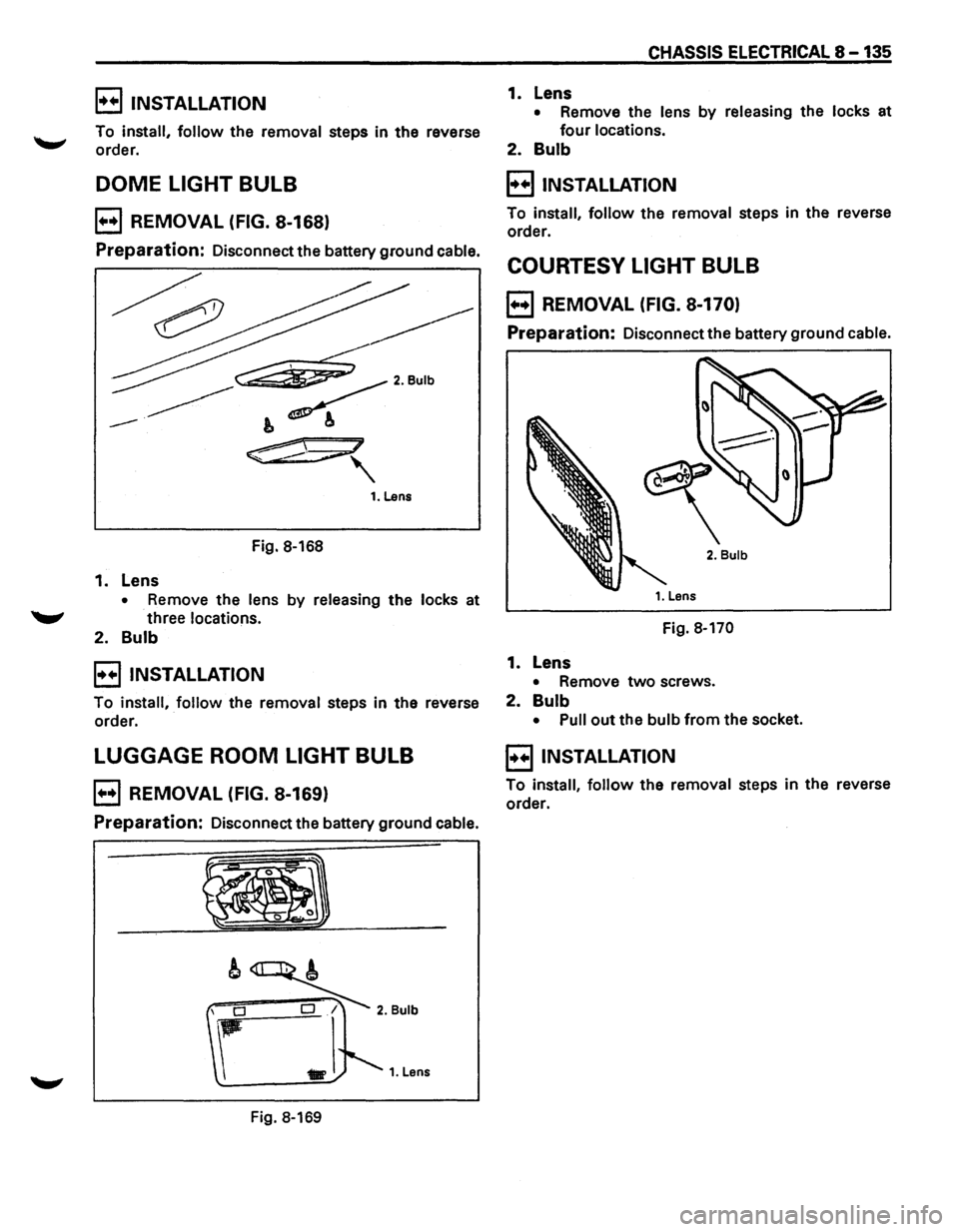
B REMOVAL (FIG. 8-168)
Preparation: Disconnect the battery ground cable.
Fig. 8-168
1. Lens
• Remove the lens by releasing the locks at
"-" three locations.
2. Bulb
B INSTALLATION
To install, follow the removal steps in the reverse
order.
LUGGAGE ROOM LIGHT BULB
B REMOVAL (FIG. 8-169)
Preparation: Disconnect the battery ground cable.
Fig. 8-169
CHASSIS ELECTRICAL 8 -135
1. Lens
• Remove the lens by releasing the locks at
four locations.
2. Bulb
B INSTALLATION
To install, follow the removal steps in the reverse
order.
COURTESY LIGHT BULB
B REMOVAL (FIG. 8-170)
Preparation: Disconnect the battery ground cable.
2. Bulb
Fig. 8-170
1. Lens
• Remove two screws.
2. Bulb
• Pull out the bulb from the socket.
E) INSTALLATION
To install, follow the removal steps in the reverse
order.
Page 1326 of 1928
8 -136 CHASSIS ELECTRICAL
MAP LIGHT SWITCH/BULB
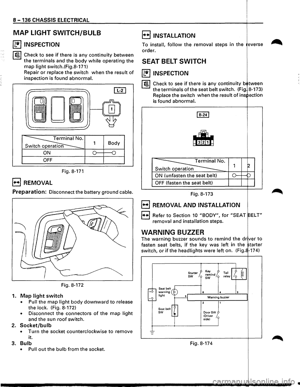
~ INSPECTION
~~~ Check to see if there is any continuity between
the terminals and the body while operating the
map light switch.(Fig.8-171)
Repair
or replace the switch when the result of
inspection is found abnormal.
I" ~ [IT]
ron
0~/~ ~
'
~· 1 Body
n
ON 0 {)
OFF
Fig. 8-171
B REMOVAL
E) INSTALLATION
To install, follow the removal steps in the everse
order.
SEAT BELT SWITCH
~ INSPECTION
I~ l Check to see if there is any continuity b tween
the terminals of the seat belt switch. (Fig 8-173)
Replace the switch when the
result of ins ection
is found abnormal.
Switch operation
ON (unfasten the seat belt)
OFF (fasten the seat belt)
Preparation: Disconnect the battery ground cable. Fig. 8-173
Fig. 8-172
1.
Map light switch
• Pull the map light body downward to release
the
lock. (Fig. 8-172)
• Disconnect the connectors of the map light
and the sun roof switch.
2. Socket/bulb
• Turn the socket counterclockwise to remove
it.
3.
Bulb
• Pull out the bulb from the socket.
B REMOVAL AND INSTALLATION
1++1 Refer to Section 10 "BODY", for "SEAT ELT"
removal and installation steps.
WARNING BUZZER
The warning buzzer sounds to remind the dr ver to
fasten seat belts, if the key was left in the tarter
switch,
or if the headlights were left on. (Fig. -174)
Seat belt warning light
Seat belt
sw
Starter sw
8
Warning buzzer
DoorSW (Driver
side)
Fig. 8-174
..
Page 1465 of 1928
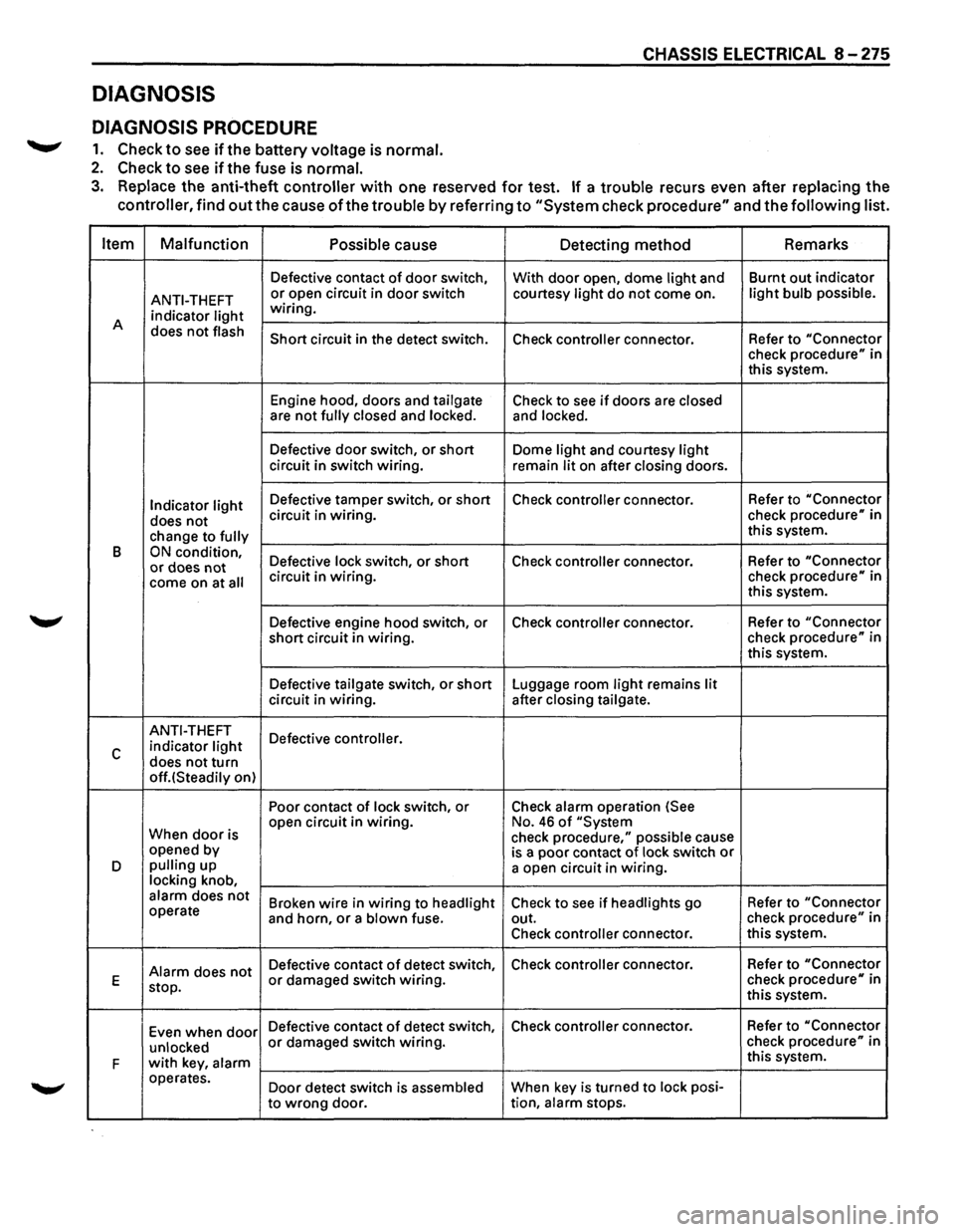
DIAGNOSIS
DIAGNOSIS PROCEDURE
.......,. 1. Check to see ifthe battery voltage is normal.
2. Check to see if the fuse is normal.
CHASSIS ELECTRICAL 8 -275
3. Replace the anti-theft controller with one reserved for test. If a trouble recurs even after replacing the
controller, find
out the cause of the trouble by referring to "System check procedure" and the following list.
Item Malfunction
Possible
cause Detecting method Remarks
Defective
contact of door switch,
With door open, dome light and Burnt
out indicator
ANTI-THEFT or open circuit in door switch courtesy light do not come on. light bulb possible.
indicator light wiring.
A does
not flash Short circuit in the detect switch.
Check controller connector. Refer to "Connector check procedure" in
this system.
Engine hood, doors and
tailgate Check to see if doors are closed are not fully closed and locked. and locked.
Defective door switch, or short Dome light and courtesy light circuit in switch wiring.
remain lit on after closing doors.
Indicator light Defective tamper switch, or short Check controller connector. Refer
to "Connector
does not circuit in wiring. check procedure" in
change to
fully this system.
B
ON condition, Defective lock switch, or short Check controller connector. Refer
to "Connector or does not come on at all circuit in wiring. check procedure" in
this system.
Defective engine hood switch, or Check
controller connector. Refer
to "Connector
short circuit in wiring. check
procedure" in
this system.
Defective
tailgate switch, or short Luggage room light remains lit circuit in wiring. after closing tailgate.
ANTI-THEFT
Defective controller.
c indicator light
does not turn off.(Steadily on) Poor contact
of lock switch, or Check alarm operation (See
When
door is open
circuit in wiring. No. 46 of "System
check procedure," possible cause
opened by
is a poor contact of lock switch or D pulling up
a open circuit in wiring. locking knob, alarm does not Broken wire in wiring to headlight Check to see if headlights go Refer
to "Connector operate
and horn, or a blown fuse. out. check procedure" in
Check
controller connector. this
system.
Alarm does not Defective contact of detect switch, Check controller connector.
Refer to "Connector
E
stop. or damaged switch wiring. check procedure" in
this system.
Even when
door Defective contact of detect switch, Check controller connector. Refer
to "Connector
unlocked
or damaged switch wiring. check procedure" in
F
with key, alarm this system.
operates. Door detect switch is
assembled When key is turned to lock posi-
to
wrong door. tion, alarm stops.
Page 1478 of 1928
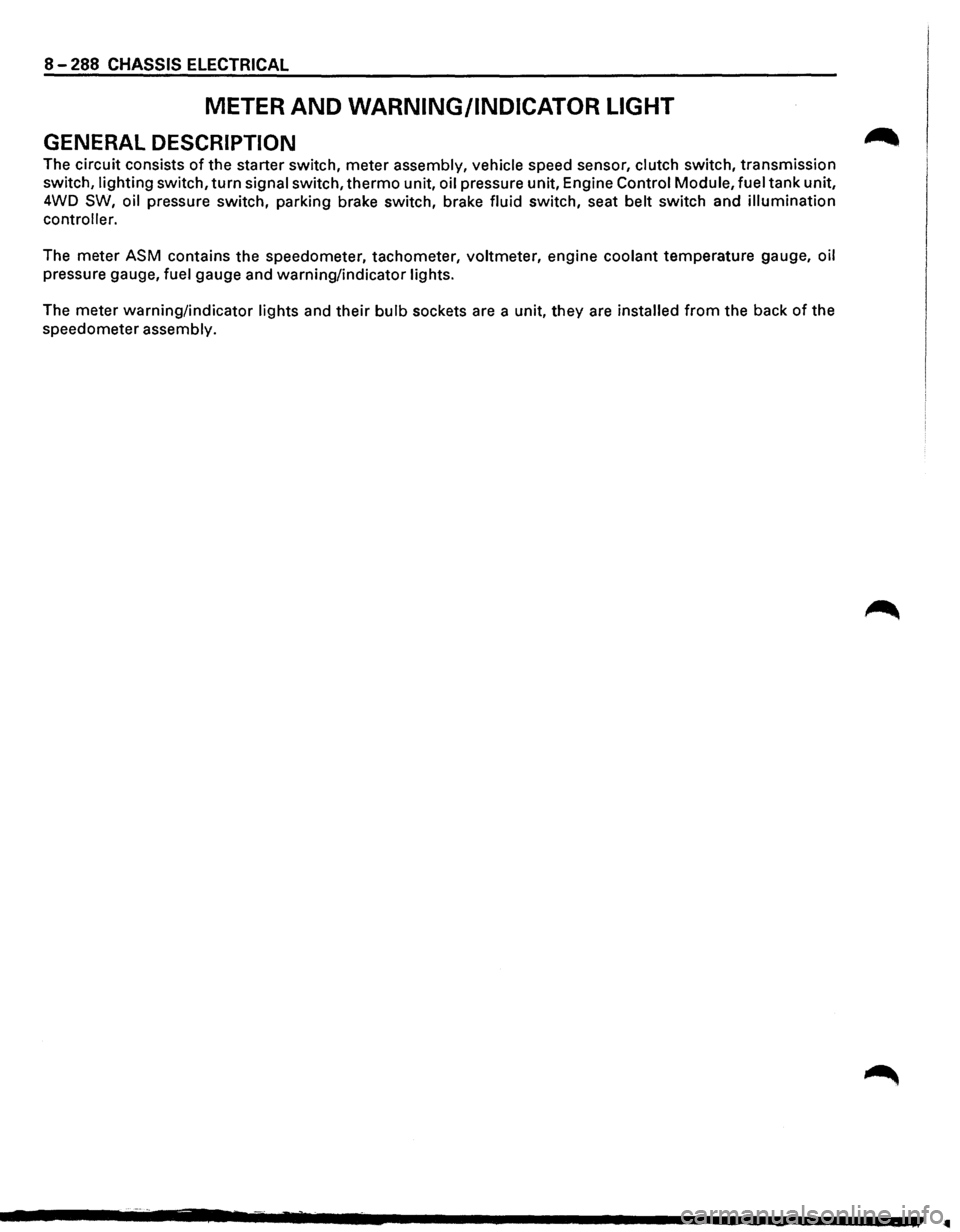
8-288 CHASSIS ELECTRICAL
METER AND WARNING/INDICATOR LIGHT
GENERAL DESCRIPTION
The circuit consists of the starter switch, meter assembly, vehicle speed sensor, clutch switch, transmission
switch, lighting switch,
turn signal switch, thermo unit, oil pressure unit, Engine Control Module, fuel tank unit,
4WD
SW, oil pressure switch, parking brake switch, brake fluid switch, seat belt switch and illumination
controller.
The meter ASM contains the speedometer, tachometer, voltmeter, engine coolant temperature gauge, oil
pressure gauge, fuel gauge and warning/indicator lights.
The meter warning/indicator lights and
their bulb sockets are a unit, they are installed from the back of the
speedometer assembly.
Page 1485 of 1928
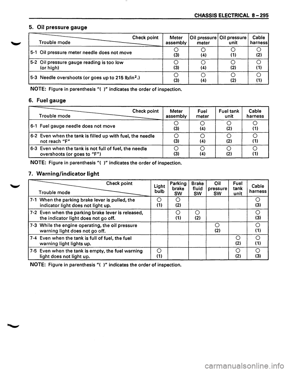
CHASSIS ELECTRICAL 8-295
5. Oil pressure gauge
Check point Meter Oil pressure Oil pressure Cable
Trouble mode
assembly meter unit harness
5-1 Oil pressure meter needle does not move 0
0 0
0 (3) (4) (1) (2)
5-2 Oil pressure
gauge reading is too low 0
0 0
0
(or
high) (3) (4) (2) (1)
5-3 Needle overshoots
(or goes up to 2151b/in2.) 0
0 0 0 (3) (4) (2)
(1)
NOTE: Figure
in parenthesis "( )" indicates the order of inspection.
6. Fuel gauge
Check point Meter Fuel Fuel tank Cable
Trouble mode assembly
meter unit harness
6-1 Fuel gauge needle does not move 0
0 0 0 (3) (4) (2) (1)
6-2 Even when the tank is filled up with fuel, the needle 0
0 0
0
not reach "F" (3) (4) (2)
(1)
6-3
Even when the tank is not full of fuel, the needle 0
0 0
0
overshoots (or goes to "F") (3) (4) (2) (1)
NOTE: Figure
in parenthesis "( )" indicates the order of inspection.
7. Warning/indicator light
~
Light Parking
Brake Oil Fuel Cable brake fluid pressure tank bulb sw sw sw unit harness
e
7-1 When the parking brake lever is pulled, the 0 0 0
indicator light does not light up. (1) (2) (3)
7-2 Even
when the parking brake lever is released, 0 0 0
the indicator light does not go off. (1) (2) (3)
7-3 While the engine operating,
the oil pressure 0 0
warning light does not go
off. (2)
(1)
7-4 Even
when the tank is full of fuel, the fuel 0 0
warning light lights
up. (2) (1)
7-5 Even
when the tank is empty, the fuel warning 0 0
0
light does not light up. (1) (2)
(3)
NOTE: Figure in parenthesis "( )" indicates the order of inspection.