bulb ISUZU TROOPER 1995 User Guide
[x] Cancel search | Manufacturer: ISUZU, Model Year: 1995, Model line: TROOPER, Model: ISUZU TROOPER 1995Pages: 1928
Page 460 of 1928
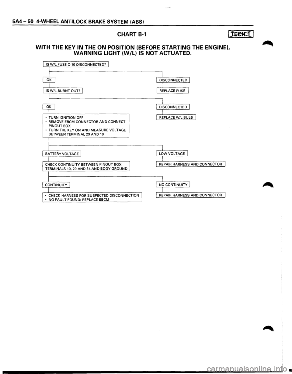
5A4-50 4-WHEEL ANTILOCK BRAKE SYSTEM (ABS)
CHART B-1
WITH THE KEY IN THE ON POSITION (BEFORE STARTING THE ENGINE),
WARNING LIGHT
{W/L) IS NOT ACTUATED.
IS W/L FUSE C-10 DISCONNECTED? j
I
IS W/L BURNT OUT? I
I
• TURN IGNITION OFF
• REMOVE EBCM CONNECTOR AND CONNECT PINOUT BOX
• TURN THE KEY ON AND MEASURE VOLTAGE BETWEEN TERMINAL 29 AND 10
I
I
BATTERYVOLTAGE I
I
CHECK CONTINUITY BETWEEN PINOUT BOX I TERMINALS 10, 20 AND 34 AND BODY GROUND
l
I CONTINUITY I
I • CHECK HARNESS FOR SUSPECTED DISCONNECTION I • NO FAULT FOUND: REPLACE EBCM
I
I
DISCONNECTED I
I L REPLACE FUSE J
I L DISCONNECTED J
I I REPLACE W/L BULB I
I
I
LOWVOLTAGE I
I
I
REPAIR HARNESS AND CONNECTOR I
I
I
NO CONTINUITY I
I I REPAIR HARNESS AND CONNECTOR I
•
Page 513 of 1928
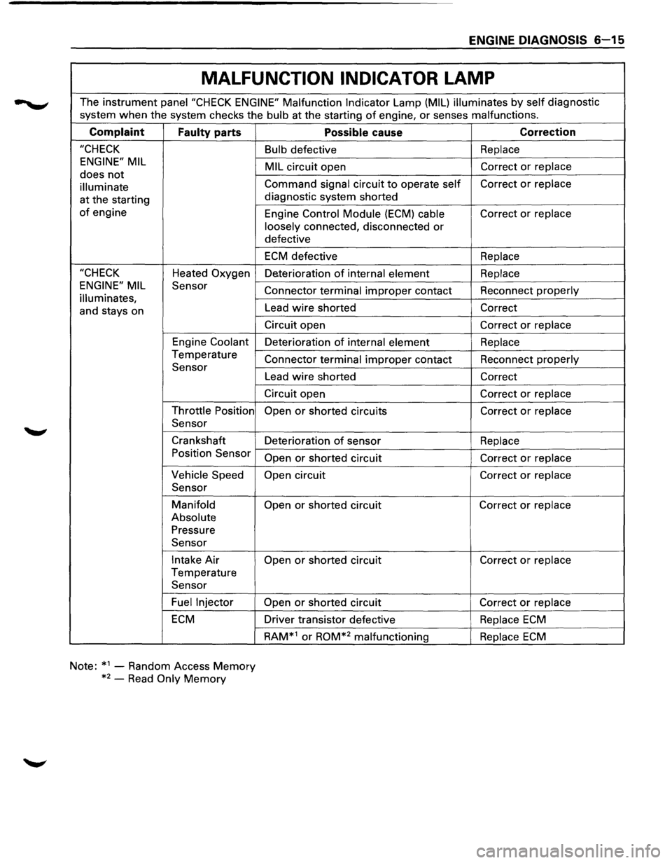
ENGINE DIAGNOSIS 6-15
MALFUNCTION INDICATOR LAMP
The instrument panei"CHECK ENGINE" Malfunction Indicator Lamp (MIL) illuminates by self diagnostic
system
when the system checks the bulb at the starting of engine, or senses malfunctions.
Complaint
Faulty parts
"CHECK
ENGINE" MIL
does not
illuminate
at the starting
of engine
"CHECK Heated Oxygen
ENGINE" MIL Sensor
illuminates,
and stays on
Engine
Coolant
Temperature Sensor
Throttle Position
Sensor
Crankshaft Position Sensor
Vehicle Speed
Sensor
Manifold
Absolute
Pressure Sensor
Intake Air
Temperature Sensor
Fuel Injector
ECM
Note: *1
-Random Access Memory
*2
-Read Only Memory
Possible cause Correction
Bulb defective Replace
MIL
circuit open Correct or replace
Command signal
circuit to operate self Correct or replace
diagnostic system shorted
Engine
Control Module (ECM) cable Correct or replace
loosely
connected, disconnected or
defective
ECM defective Replace
Deterioration of internal element Replace
Connector terminal improper contact Reconnect properly
Lead wire shorted Correct
Circuit
open Correct or replace
Deterioration of internal element Replace
Connector terminal improper contact Reconnect properly
Lead wire shorted Correct
Circuit
open Correct or replace
Open
or shorted circuits Correct or replace
Deterioration of sensor Replace
Open
or shorted circuit Correct or replace
Open
circuit Correct or replace
Open
or shorted circuit Correct or replace
Open
or shorted circuit Correct or replace
Open
or shorted circuit Correct or replace
Driver transistor defective Replace ECM
RAM*1 or ROM*2 malfunctioning Replace ECM
Page 700 of 1928
6E2-4 DRIVEABILITY AND EMISSIONS
BASIC KNOWLEDGE REQUIRED
Before using this section of the Service Manual,
there are some areas that you should be familiar
with. Without this basic knowledge, you will have
trouble using the diagnostic procedures
contained in this section.
BASIC ELECTRIC CIRCUITS
You should understand the basic theory of
electricity, and know the meaning of voltage,
amps, and ohms. You should understand what
happens in a circuit with an open or a shorted
wire. You
should be able to read and understand a
wiring diagram. A shortto ground is referred to as
a ground to distinguish it from a short between
wires.
USE OF CIRCUIT TESTING TOOLS
You should know how to use a test light, how to
connect and use a tachometer, and
how to use
jumper wires to by-pass components to test
circuits. Care
should be taken to not deform the
terminal when testing.
USE OF DIGITAL VOLT-OHM METER
(DVOM)
You should be familiar with the Digital Volt-Ohm
Meter, particularly special tool J-39200 or
equivalent. You should be able to measure
voltage, resistance, and current and know how to
use the meter correctly.
The
Digital Volt-Ohm Meter is covered in the
"Special Tools" portion of this section.
DIAGNOSTIC INFORMATION
The diagnostic "Trouble Tree" charts and func
tional checks in this manual are designed to locate
a faulty circuit or component through logic based
on the process
of elimination. The charts are
prepared
with the requirement that the vehicle
functioned correctly at the time of assembly and
that there are no multiple failures.
The Engine Control Module (ECM) performs a
continual self-diagnosis on certain control
functions. This diagnostic capability is
complemented by the diagnostic procedures
contained in this
manual. The ECM's language for
communicating the source of a malfunction is a
system
of Diagnostic Trouble Codes (DTCs). The
DTC(s) are
two or three digit numbers that can
range from12 to
51. When a malfunction is
detected by the ECM, a DTC is set and the
Malfunction Indicator Lamp is illuminated.
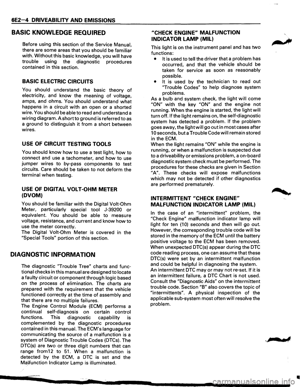
"CHECK ENGINE" MALFUNCTION
INDICATOR
LAMP (MIL)
This light is on the instrument panel and has two
functions:
• It is used to tell the driver that a problem has
occurred, and that the
vehicle should be
taken
for service as soon as reasonably
possible.
• It
is used by the technician to read out
'Trouble Codes" to help diagnose system
problems.
As a bulb and system check, the light will come
"ON" with the key "ON" and the engine not
running. When the engine is started, the light will
turn off. If the light remains on, the self-diagnostic
system has detected a
problem. If the problem
goes away, the light will go out in most cases after
10 seconds, but a Trouble Code will remain stored
in the
ECM.
When the light remains "ON" while the engine is
running,
or when a malfunction is suspected due
to a
driveability or emissions problem, a on-board
diagnostic system check
must be performed. The
procedures
for these checks are given in Section
"A". These checks will expose malfunctions
which may
not be detected if other diagnostics
are performed
prematurely.
INTERMITTENT "CHECK ENGINE"
MALFUNCTION INDICATOR
LAMP (MIL)
In the case of an "intermittent" problem, the
"Check Engine"
malfunction indicator lamp will
light
for ten (1 0) seconds and then will go out.
However, the corresponding
trouble code will be
stored in the
memory of the ECM until the battery
positive
voltage to the ECM has been removed.
When unexpected DTC(s) appear during the
DTC
code reading process, one can assume that these
DTC(s) were set by an intermittent malfunction
and could be helpful in diagnosing the system.
An intermittent
DTC may or may not re-set. If it is
an intermittent failure, a DTC Chart is not used.
Consult the "Diagnostic Aids" on the intermittent
trouble code. Section "B" also covers the topic of
"intermittents". A physical inspection of the
applicable sub-system most often will resolve the
problem.
II
Page 732 of 1928
6E2-36 DRIVEABILITV AND EMISSIONS
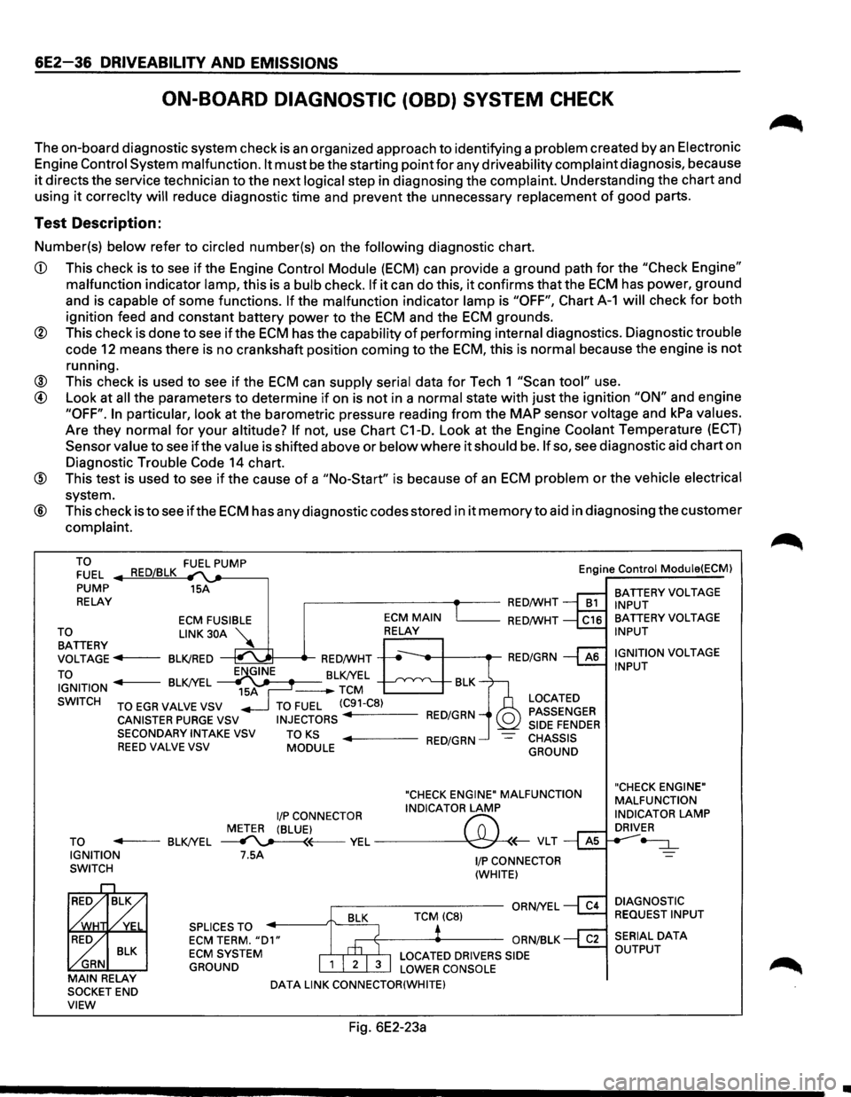
ON-BOARD DIAGNOSTIC (OBD) SYSTEM CHECK
The on-board diagnostic system check is an organized approach to identifying a problem created by an Electronic
Engine
Control System malfunction. It must be the starting point for any driveability complaint diagnosis, because
it directs the service technician to the next logical step in diagnosing the complaint. Understanding the chart and
using
it correclty will reduce diagnostic time and prevent the unnecessary replacement of good parts.
Test Description:
Number(s) below refer to circled number(s) on the following diagnostic chart.
CD This check is to see if the Engine Control Module (ECM) can provide a ground path for the "Check Engine"
malfunction indicator lamp, this is a bulb check. If it can do this, it confirms that the ECM has power, ground
and is capable
of some functions. If the malfunction indicator lamp is "OFF", Chart A-1 will check for both
ignition feed and constant battery power to the
ECM and the ECM grounds.
® This check is done to see if the ECM has the capability of performing internal diagnostics. Diagnostic trouble
code
12 means there is no crankshaft position coming to the ECM, this is normal because the engine is not
running.
® This check is used to see if the ECM can supply serial data for Tech 1 "Scan tool" use.
@ Look at all the parameters to determine if on is not in a normal state with just the ignition "ON" and engine
"OFF". In particular, look at the barometric pressure reading from the MAP sensor voltage and kPa values.
Are they normal for
your altitude? If not, use Chart C1-D. Look at the Engine Coolant Temperature (ECT)
Sensor value to see if the value is shifted above or below where it should be. If so, see diagnostic aid chart on
Diagnostic Trouble
Code 14 chart.
@ This test is used to see if the cause of a "No-Start" is because of an ECM problem or the vehicle electrical
system.
® This check is to see ifthe ECM has any diagnostic codes stored in it memory to aid in diagnosing the customer
complaint.
TO FUEL
PUMP
RELAY 15A
,------------+--RED/WHT Engine
Control Module(ECM)
BATTERY
VOLTAGE INPUT
ECM FUSIBLE L_ __ RED/WHT
~~TTERY LINK 30A ~
VOLTAGE ..,.,.f----BLK/RED
TO
~t-----tr-RED/WHT -----,t--+---.-RED/GRN
IGNITION BLK/YEL J-------BLK/YEL -TCM BLK
SWITCH
TO EGR VALVE VSV
CANISTER PURGE VSV SECONDARYINTAKEVSV REED VALVE VSV
TO FUEL (C91-C8)
INJECTORS RED/GRN
TO KS MODULE ..,._ ___ RED/GRN
LOCATED
PASSENGER
SIDE
FENDER CHASSIS
GROUND
"CHECK ENGINE" MALFUNCTION
I/P CONNECTOR INDICATOR LAMP
METER (BLUE)
f'7:' TO ..,._ __ BLK/YEL ~~VEL~(;-VLT IGNITION
SWITCH 7.5A
SPLICES TO
ECM TERM. "D1" ECM SYSTEM
GROUND
DATA LINK CONNECTOR(WHITE)
Fig. 6E2-23a
1/P CONNECTOR
(WHITE)
BATTERY VOLTAGE INPUT
IGNITION
VOLTAGE INPUT
"CHECK ENGINE"
MALFUNCTION
INDICATOR
LAMP DRIVER
-=:J._
DIAGNOSTIC
REQUEST INPUT
•
Page 734 of 1928
6E2-38 DRIVEABILITV AND EMISSIONS
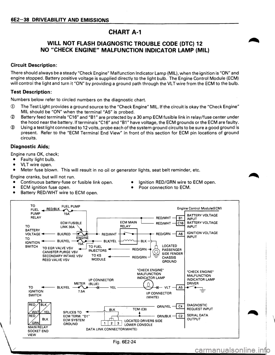
CHART A-1
WILL NOT FLASH DIAGNOSTIC TROUBLE CODE (DTC) 12
NO "CHECK ENGINE" MALFUNCTION INDICATOR LAMP (MIL)
Circuit Description:
There should always be a steady "Check Engine" Malfunction Indicator Lamp (MIL), when the ignition is "ON" and
engine stopped. Battery positive
voltage is supplied directly to the light bulb. The Engine Control Module (ECM)
will control the light and turn it "ON" by providing a ground path through the VL T wire from the ECM to the bulb.
Test Description:
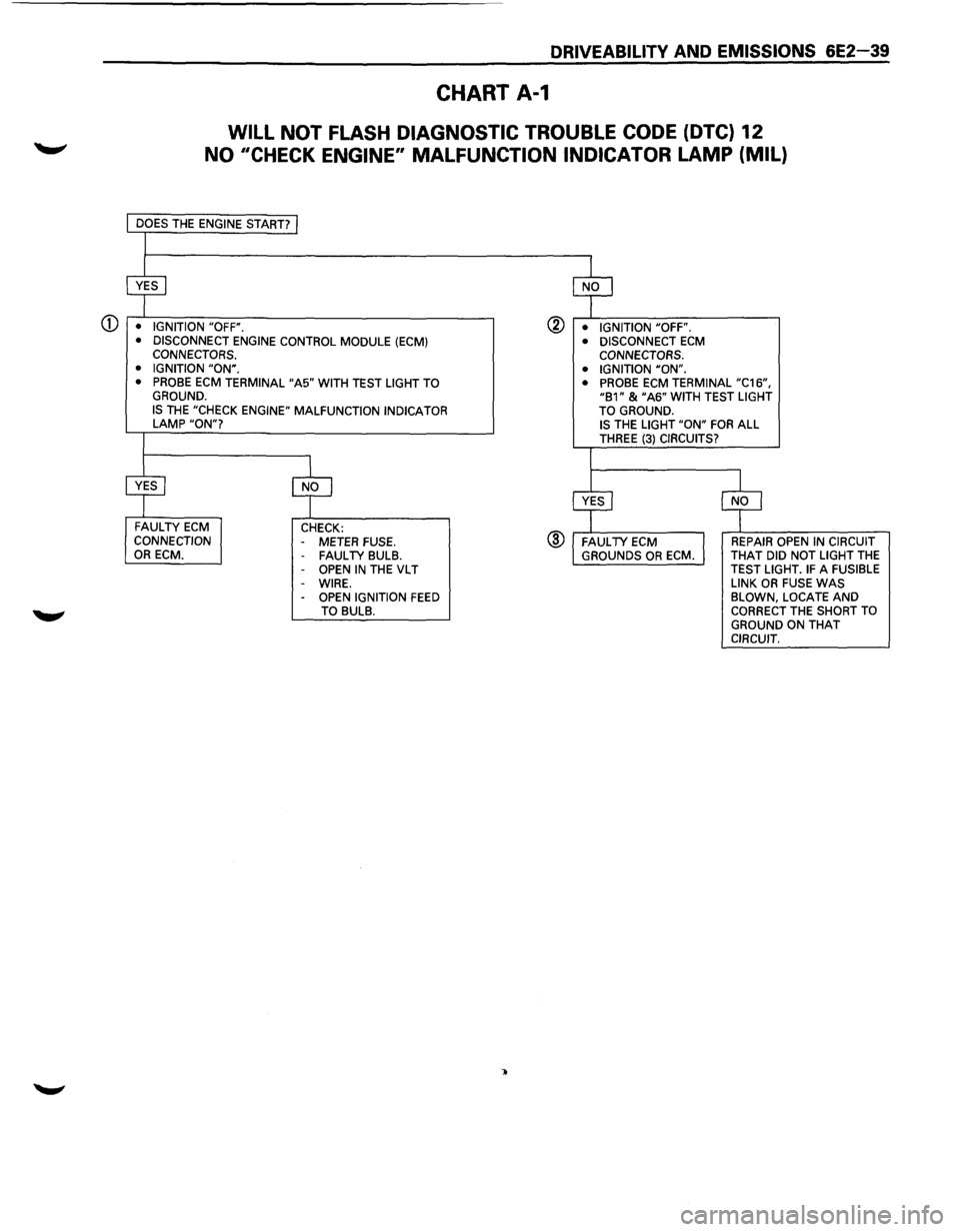
Numbers below refer to circled numbers on the diagnostic chart.
CD The Test Light provides a ground source to the "Check Engine" MIL. If the circuit is okay the "Check Engine"
MIL should
be "ON" when the terminai"A5" is probed.
® Battery feed terminals "C16" and "B1" are protected by a 30 amp ECM fusible link in relay/fuse center under
the hood near the battery.
If terminals "C16" and "B1" have voltage, the ECM grounds or the ECM are faulty.
® Using a test light connected to 12 volts, probe each of the system ground circuits to be sure a good ground is
present. Refer to the
"ECM Terminal End View" in front of this section for ECM pin locations of ground
circuits.
Diagnostic Aids;
Engine runs OK, check;
• Faulty light bulb.
•
VL T wire open.
• Meter fuse blown. This will result in no oil or generator lights, seat belt reminder, etc.
Engine cranks, but
will not run.
• Continuous battery-fuse or fusible link open. • Ignition RED/GRN wire to ECM open.
• ECM ignition fuse open. • Poor connection to ECM.
• Battery RED/WHT wire to ECM open.
TO FUEL .._..,==~ ,__,__-----, PUMP 15A
RELAY .--------~~-RED/WHT Engine
Control
Module(ECM)
BATIERY VOLTAGE
INPUT
ECM FUSIBLE RED/WHT TO LINK 30A '\.. BATIERY ~ VOLTAGE---BLK!RED ~---.-RED/WHT
TO IGNITION - BLK!YEL ~~~-BLK!YEL --'--'~"'---..__
SWITCH TO EGR VALVE VSV
CANISTER PURGE VSV
SECONDARY INTAKE VSV
REED VALVE VSV TO KS MODULE
LOCATED
PASSENGER
SIDE FENDER CHASSIS GROUND
"CHECK ENGINE"
MALFUNCTION
I/P CONNECTOR INDICATOR LAMP
METER (BLUE)
("";:; TO - BLK!YEL ~(---VEL~(;-VLT IGNITION 7.5A SWITCH
BLK ~ GRN MAIN RELAY
SOCKETEND SPLICES
TO ECM TERM. "D1" ECM SYSTEM GROUND
DATA
LINK CONNECTOR(WHITE)
1/P CONNECTOR
(WHITE)
BA TIERY VOLTAGE INPUT
IGNITION
VOLTAGE INPUT
"CHECK ENGINE"
MALFUNCTION
INDICATOR
LAMP DRIVER
~
DIAGNOSTIC REQUEST INPUT
' VIEW Fig. 6E2-24
./ .................................... __________________________ _
Page 735 of 1928
DRIVEABILITV AND EMISSIONS 6E2-39
CHART A-1
WILL NOT FLASH DIAGNOSTIC TROUBLE CODE (DTC) 12
NO 11CHECK ENGINE" MALFUNCTION INDICATOR LAMP (MIL)
CD • IGNITION "OFF".
• DISCONNECT ENGINE CONTROL MODULE (ECM) CONNECTORS.
• IGNITION "ON". • PROBE ECM TERMINAL "A5" WITH TEST LIGHT TO GROUND. IS THE "CHECK ENGINE" MALFUNCTION INDICATOR LAMP "ON"?
FAULTY ECM CONNECTION OR ECM. CHECK:
- METER FUSE. FAUL TV BULB. OPEN IN THE VL T
-WIRE. -OPEN IGNITION FEED TO BULB.
@ • IGNITION "OFF".
®
• DISCONNECT ECM CONNECTORS.
• IGNITION "ON".
• PROBE
ECM TERMINAL "C16", "B1" & "A6" WITH TEST LIGHT
TO GROUND. IS THE LIGHT "ON" FOR ALL THREE (3) CIRCUITS?
REPAIR OPEN IN CIRCUIT
THAT DID NOT LIGHT THE TEST LIGHT. IF A FUSIBLE
LINK OR FUSE WAS BLOWN, LOCATE AND CORRECT THE SHORT TO
GROUND ON THAT CIRCUIT.
Page 736 of 1928
6E2-40 DRIVEABILITY AND EMISSIONS
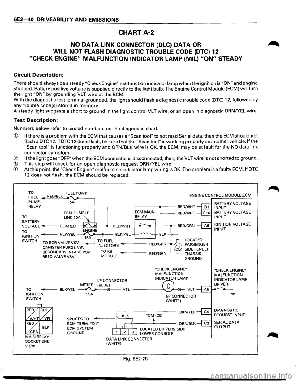
CHART A-2
NO DATA LINK CONNECTOR (DLC) DATA OR
WILL NOT FLASH DIAGNOSTIC TROUBLE CODE (DTC) 12
"CHECK ENGINE" MALFUNCTION INDICATOR LAMP (MIL) "ON" STEADY
Circuit Description:
There should always be a steady "Check Engine" malfunction indicator lamp when the ignition is "ON" and engine
stopped. Battery positive
voltage is supplied directly to the light bulb. The Engine Control Module (ECM) will turn
the
light "ON" by grounding VLT wire at the ECM.
With the diagnostic test terminal grounded, the light should flash a diagnostic trouble code (DTC) 12, followed by
any trouble code(s) stored in memory.
A steady
light suggests a short to ground in the light control VLT wire, or an open in diagnostic ORNIYEL wire.
Test Description:
Numbers below refer to circled numbers on the diagnostic chart.
CD If there is a problem with the ECM that causes a "Scan tool" to not read Serial data, then the ECM should not
flash a DTC 12.1f DTC 12 does flash, be sure that the "Scan tool" is working properly on anothervehicle.lfthe
"Scan tool" is functioning properly and ORN/BLK wire is OK, the ECM, may be at fault for the NO data link
connector symptom.
@ If the light goes "OFF" when the ECM connector is disconnected, then, the VLTwire is not shorted to ground.
® This step will check for an open diagnostic request ORN/YEL wire.
® At this point, the "Check Engine" malfunction indicator lamp wiring is OK. The problem is a faulty ECM.IfDTC
12 does not flash, the ECM should be replaced.
TO FUEL PUMP
FUEL RED/BLK ENGINE CONTROL MODULE(ECM)
PUMP 15A
RELAY
,.-------------.--RED/WHT
TO BATTERY
ECM FUSIBLE
LINK 30A
VOLTAGE
...,. .. 1---BLK!RED
TO IGNITION
SWITCH ENGINE
15A
'------RED/WHT
BLK
BLK!YEL
~ BLK!YEL
TO EGA VALVE VSV TO FUEL CANISTER PURGE VSV INJECTORS ..._ ___ RED/GRN
LOCATED
PASSENGER
SIDE
FENDER CHASSIS
GROUND
SECONDARY
INTAKE VSV TO KS ..._ ___ RED/GRN REED VALVE VSV MODULE
"CHECK ENGINE"
MALFUNCTION
liP CONNECTOR INDICATOR
LAMP
METER (BLUE)
f'7:'
TO -----BLK!YEL ~~ YEL ---\C:;J-
BLK
GRN
MAIN RELAY SOCKET END VIEW
7.5A
SPLICES TO ECM TERM. "D1" ECM SYSTEM
GROUND
DATA LINK CONNECTOR
(WHITE)
Fig. 6E2-25
I/P CONNECTOR
(WHITE)
BATTERY VOLTAGE
INPUT
BATTERY VOLTAGE
INPUT
IGNITION
VOLTAGE INPUT
"CHECK ENGINE"
MALFUNCTION
INDICATOR
LAMP DRIVER
~
DIAGNOSTIC
REQUEST INPUT
Page 1016 of 1928
7A-144 AUTOMATIC TRANSMISSION (4L30-E)
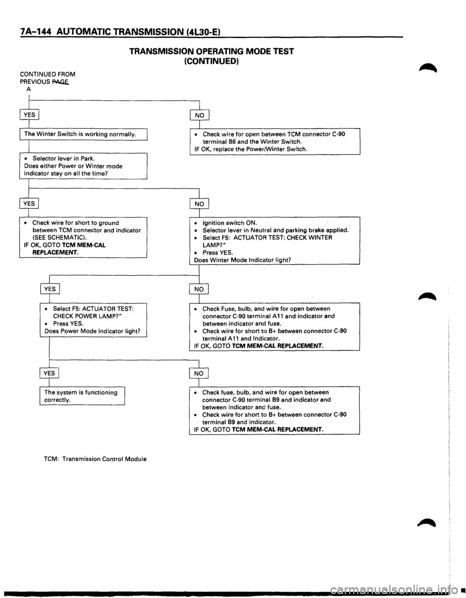
TRANSMISSION OPERATING MODE TEST
(CONTINUED)
CONTINUED FROM
PREVIOUS
PAGE. A
I
$
The Winter Switch is working normally.
I
• Selector lever in Park .
Does
either Power or Winter mode indicator stay on all the time?
I
$
• Check wire for short to ground
between
TCM connector and indicator (SEE SCHEMATIC).
IF OK, GOTO TCM MEM-CAL REPLACEMENT.
$
• Select F5: ACTUATOR TEST: CHECK POWER LAMP?"
• Press YES .
Does Power Mode Indicator light?
~
The system is functioning
J correctly.
TCM:
Transmission Control Module
$
• Check wire for open between TCM connector C-90 terminal 86 and the Winter Switch.
IF OK, replace the Power/Winter Switch.
$
• Ignition switch ON .
• Selector lever in Neutral and parking brake applied .
• Select F5: ACTUATOR TEST: CHECK WINTER
LAMP?"
• Press YES .
Does Winter Mode Indicator light?
I
$
• Check Fuse, bulb, and wire for open between
connector C-90 terminal A 11 and indicator and
between indicator and fuse.
• Check wire for short til 8+ between connector C-90
terminal A 11 and Indicator. IF OK, GOTO TCM MEM-CAL REPLACEMENT.
$
• Check fuse, bulb, and wire for open between
connector C-90 terminal 89 and indicator and
between indicator andl fuse.
• Check wire for short to 8+ between connector C-90 terminal 89 and indicator.
IF OK, GOTO TCM MEM-CAL REPLACEMENT.
•
Page 1191 of 1928

CHASSIS ELECTRICAL 8-1
·SECTION 8
CHASSIS ELECTRICAL
'\f CAUTION: .
When fasteners are removed, always reinstall them at the same location from which they were removed.
If a fastener needs to be replaced, use the correct part number fastener for that application. If the correct
part number fastener is not
available, a fastener of equal size and strength (or stronger) may be used.
Fasteners that are not reused, and those requiring thread
locking compound, will be called out. The correct
torque
values must be used when installing fasteners that require it. If the above conditions are not
followed, parts or system damage could result.
CONTENTS
General Information .................................... 8-2
Notes for Working on Electrical
Items .................................................... 8-2
Symbols and Abbreviations ................. 8-8
Symbols ............................................ 8-8
Abbreviations ................................... 8-9
Parts for Electrical Circuit ..................... 8-10
Wiring ............................................... 8-10
Fuse .................................................. 8-11
Fusible Link ....................................... 8-12
Circuit Breaker ................................... 8-12
Relay ................................................. 8-12
Relay Specifications and
Configurations ................................ 8-13
Diode ................................................. 8-14
Connector ......................................... 8-15
Reading the Circuit Diagram ................ 8-17
Main Data and Specifications .................... 8-19
Bulb Specifications ................................ 8-19
Fuse,
Fusible Link and
Circuit Breaker Location ..................... 8-21
Fuse
Block Circuit .................................. 8-22
Reference Table of Fuse, Fusible
Link and Circuit Breaker ..................... 8-23
Relay Location ....................................... 8-27
Diode Location .......................................
8-28
Grounding Point .................................... 8-29
Reference Table ................................ 8-29
Location ............................................ 8-31
Cable Harness Routing .......................... 8-34
System Repair .............................................. 8-38
Start and Charging ................................ 8-38
Engine Control Module
(ECM) ................................................... 8-47
Headlight and Fog Light ........................ 8-58
Front Side Marker Light, Parking Light,
Taillight, License Plate Light and
Illumination Light .............................. 8-76
Stoplight and Rear Defogger .............. 8-92
Turn Signal Light, Hazard
Warning
Light, Cornering Light,
Backup
Light and Horn ..................... 8-106
Dome Light, Luggage room Light,
Courtesy Light, Map Light,
Seat Belt Switch and
Warning Buzzer ................................. 8-128
Power Door Lock ................................. 8-142
Power
Window .................................... 8-156
Cruise
Control ...................................... 8-172
Anti-Lock Brake
System (ABS) ........... 8-178
Rear
Wheel Anti-Lock Brake
System (RWAL) ................................. 8-185
Transmission
Control Module
(TCM) ................................................. 8-192
A/T Shift Lock ...................................... 8-200
Windshield
Wiper/Washer and
Rear
Wiper/Washer .......................... 8-205
Headlight wiper /washer ..................... 8-232
Audio, Auto Antenna,
Cigarette
Lighter and digital clock ... 8-246
Power Door Mirror ............................... 8-254
Anti-theft System ................................ 8-270
Meter and Warning/Indicator Light ... 8-288
A/T Shift Indicator ............................... 8-336
Heater and
Air Conditioning ............... 8-340
Sun
Roof ............................................... 8-346
Power Seat ........................................... 8-360
Seat
Heater .......................................... 8-37 4
Supplemental Restraint
System (SRS) -AIR BAG ................... 8-382
Page 1198 of 1928
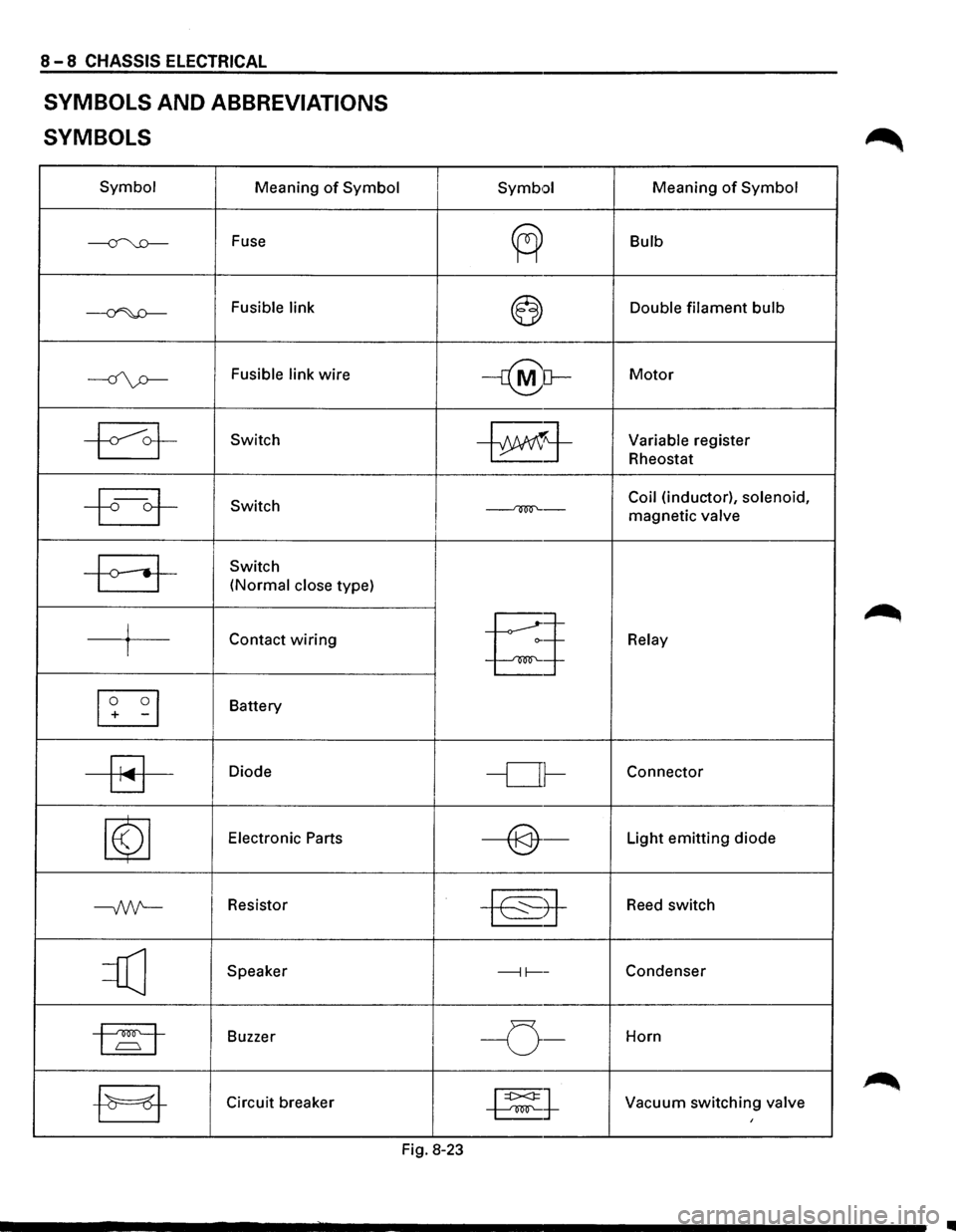
8-8 CHASSIS ELECTRICAL
SYMBOLS AND ABBREVIATIONS
SYMBOLS
Symbol Meaning of Symbol
~ Fuse
~ Fusible link
----if\p-Fusible link wire
~ Switch
~ Switch
-a-
Switch
(Normal close type)
j Contact wiring I
[I] -I
Battery
~
Diode
~
Electronic Parts
--Nt-Resistor
=Q] Speaker
1~1 Buzzer I
-EJ-Circuit breaker
I Symb•:>l Meaning of Symbol
~
Bulb
~ Double filament bulb
-r@[}-Motor
~j-Variable register
Rheostat
Coil (inductor), solenoid,
~-magnetic valve I
§
Relay
-or-Connector
----@-Light emitting diode
~8-
Reed switch
---11----Condenser
I -o-Horn
~t Vacuum switching valve I
Fig. 8-23
•