bulb ISUZU TROOPER 1995 Workshop Manual
[x] Cancel search | Manufacturer: ISUZU, Model Year: 1995, Model line: TROOPER, Model: ISUZU TROOPER 1995Pages: 1928
Page 31 of 1928
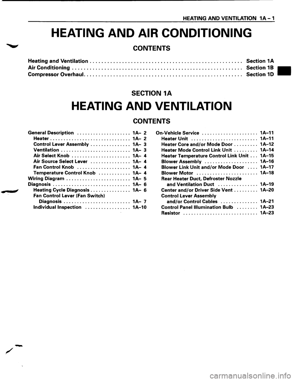
HEATING AND VENTILATION 1A-1
HEATING AND AIR CONDITIONING
CONTENTS
Heating and Ventilation .................................................... Section 1A
Air Conditioning . . . . . . . . . . . . . . . . . . . . . . . . . . . . . . . . . . . . . . . . . . . . . . . . . . . . . . . . . . Section 1 B
Compressor Overhaul. . .
. . . . . . . . . . . . . . . . . . . . . . . . . . . . . . . . . . . . . . . . . . . . . . . . . . . Section 1 D
SECTION 1A
HEATING AND VENTILATION
CONTENTS
General Description .................... 1A-2 On-Vehicle Service ..................... 1A-11
Heater . . . . . . . . . . . . . . . . . . . . . . . . . . . . . . 1
A-2 Heater Unit . . . . . . . . . . . . . . . . . . . . . . . . . 1A-11
Control Lever Assembly . . . . . . . . . . . . . . . 1 A-3 Heater Core and/or Mode Door ......... 1A-12
Ventilation .......................... 1A-3 Heater Mode Control Link Unit ......... 1A-14
Air Select Knob . . . . . . . . . . . . . . . . . . . . . . 1 A-4 Heater Temperature Control Link Unit ... 1A-15
Air Source Select Lever ............... 1A-4 Blower Assembly .................... 1A-16
Fan Control Knob .................... 1A-4 Blower Link Unit and/or Mode Door . . . . 1A-17
Temperature Control Knob ............ 1A-4 Blower Motor ....................... 1A-18
Wiring Diagram . . . . . . . . . . . . . . . . . . . . . . . . 1A-5
Rear Heater Duct, Defroster Nozzle
Diagnosis ............................. 1A-6 and Ventilation Duct ............... 1A-19
.. # Heating Cycle Diagnosis ............... 1A-6 Center and/or Driver Side Vent ......... 1A-20
Fan Control Lever (Fan Switch) Control Lever Assembly
Diagnosis . . . . . . . . . . . . . . . . . . . . . . . . . 1 A-7 and/or Control Cables .............. 1A-21
Individual Inspection ................. 1A-10 Control Panel Illumination Bulb ........ 1A-23
Resistor ............................ 1A-23
Page 53 of 1928
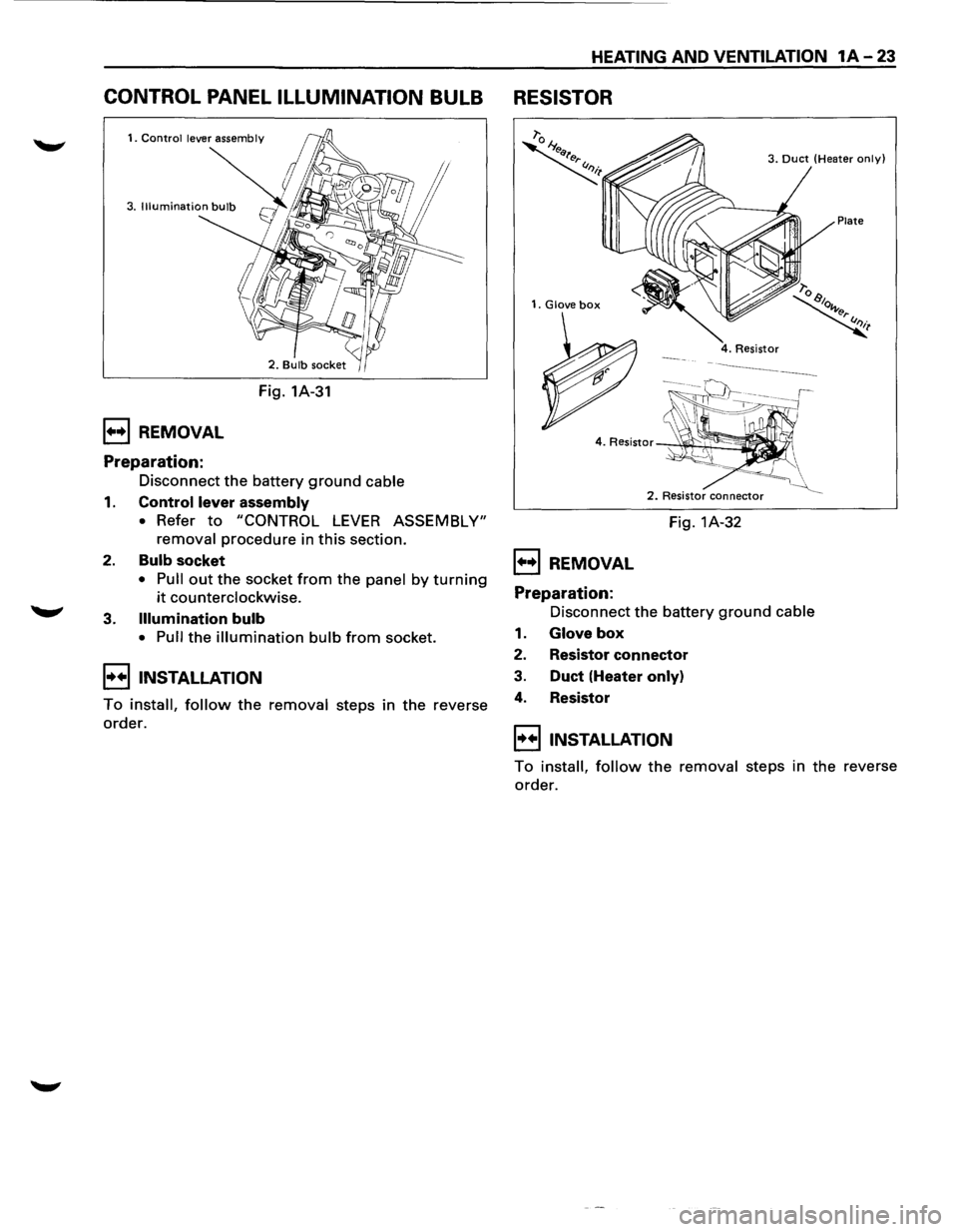
CONTROL PANEL ILLUMINATION BULB
1••1 REMOVAL
Preparation:
Fig. 1A-31
Disconnect
the battery ground cable
1. Control lever assembly
• Refer to "CONTROL LEVER ASSEMBLY"
removal
procedure in this section.
2. Bulb socket
• Pull out the socket from the panel by turning
it counterclockwise.
3.
Illumination bulb
• Pull the illumination bulb from socket.
I••IINSTALLATION
To install, follow the removal steps in the reverse
order.
HEATING AND VENTILATION 1A-23
RESISTOR
1. Glove box
1••1 REMOVAL
Preparation:
3. Duct (Heater only)
Plate
2. Resistor connector
Fig. 1A-32
Disconnect the battery
ground cable
1. Glove box
2. Resistor connector
3. Duct (Heater only)
4. Resistor
I••IINSTALLATION
To install, follow the removal steps in the reverse
order.
Page 55 of 1928
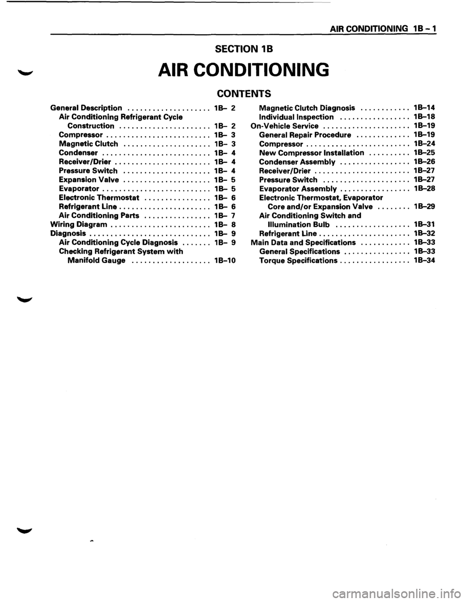
AIR CONDITIONING 1 B - 1
SECTION 18
AIR CONDITIONING
CONTENTS
General Description . . . . . . . . . . . . . . . . . . . . 1 B-2
Air Conditioning Refrigerant Cycle
Construction . . . . . . . . . . . . . . . . . . . . . . 1 8-2
Compressor . . . . . . . . . . . . . . . . . . . . . . . . . 1
B-3
Magnetic Clutch . . . . . . . . . . . . . . . . . . . . . 1 8-3
Condenser . . . . . . . . . . . . . . . . . . . . . . . . . . 1
8-4
Receiver
/Drier . . . . . . . . . . . . . . . . . . . . . . . 1 B-4
Pressure
Switch . . . . . . . . . . . . . . . . . . . . . 1 8-4
Expansion
Valve . .
. . . . . . . . . . . . . . . . . . .
18-5
Evaporator . . . . . . . . . . . . . . . . . . . . . . . . . . 1 B-5
Electronic Thermostat . . . . . . . . . . . . . . . . 1 B-6
Refrigerant Line . . . . . . . . . . . . . . . . . . . . . . 1
B-6
Air Conditioning Parts . . . . . . . . . . . . . . . . 1 B-7
Wiring Diagram . . . . . . . . . . . . . . . . . . . . . . . . 18-8
Diagnosis . . . . . . . . . . . . . . . . . . . . . . . . . . . . . 1
B-9
Air Conditioning Cycle Diagnosis . . . . . . . 18-9
Checking Refrigerant
System with
Manifold Gauge ................... 18-10
Magnetic Clutch Diagnosis ............ 18-14
Individual Inspection ................. 18-18
On-Vehicle Service ..................... 18-19
General Repair Procedure ............. 18-19
Compressor . . . . . . . . . . . . . . . . . . . . . . . . . 18-24
New Compressor Installation . . . . . . . . . . 1 B-25
Condenser Assembly . . . . . . . . . . . . . . . . . 1 B-26
Receiver/Drier ....................... 18-27
Pressure Switch ..................... 18-27
Evaporator Assembly . . . . . . . . . . . . . . . . . 1 B-28
Electronic Thermostat, Evaporator
Core
and/or Expansion Valve ........ 18-29
Air Conditioning Switch and
Illumination Bulb . . . . . . . . . . . . . . . . . . 1 B-31
Refrigerant Line ...................... 18-32
Main Data and Specifications ............ 18-33
General Specifications . . . . . . . . . . . . . . . . 18-33
Torque Specifications ................. 18-34
Page 85 of 1928
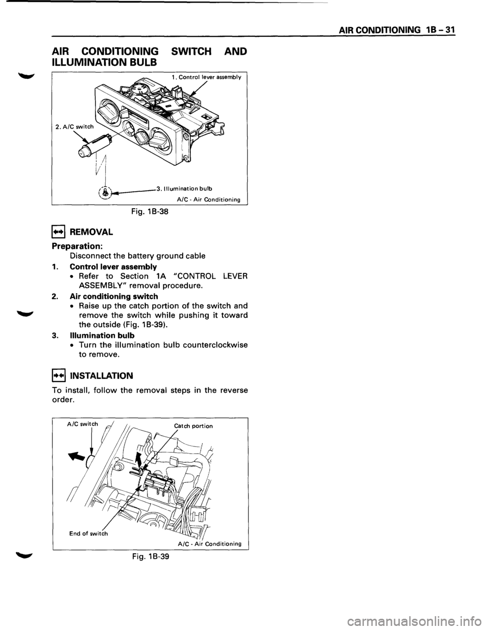
AIR CONDITIONING SWITCH AND
ILLUMINATION BULB
i-..---3. Illumination bulb
1++1 REMOVAL
Preparation:
Fig. 18-38
A/C -Air Conditioning
Disconnect the battery ground cable
1. Control lever assembly
• Refer to Section 1A "CONTROL LEVER
ASSEMBLY" removal procedure.
2. Air conditioning switch
• Raise up the catch portion of the switch and
remove the switch while pushing it toward
the outside (Fig. 1 B-39).
3. Illumination bulb
• Turn the illumination bulb counterclockwise
to remove.
I••IINSTALLATION
To install, follow the removal steps in the reverse
order.
End of switch
Fig. 18-39
AIR CONDITIONING 1 B -31
Page 128 of 1928
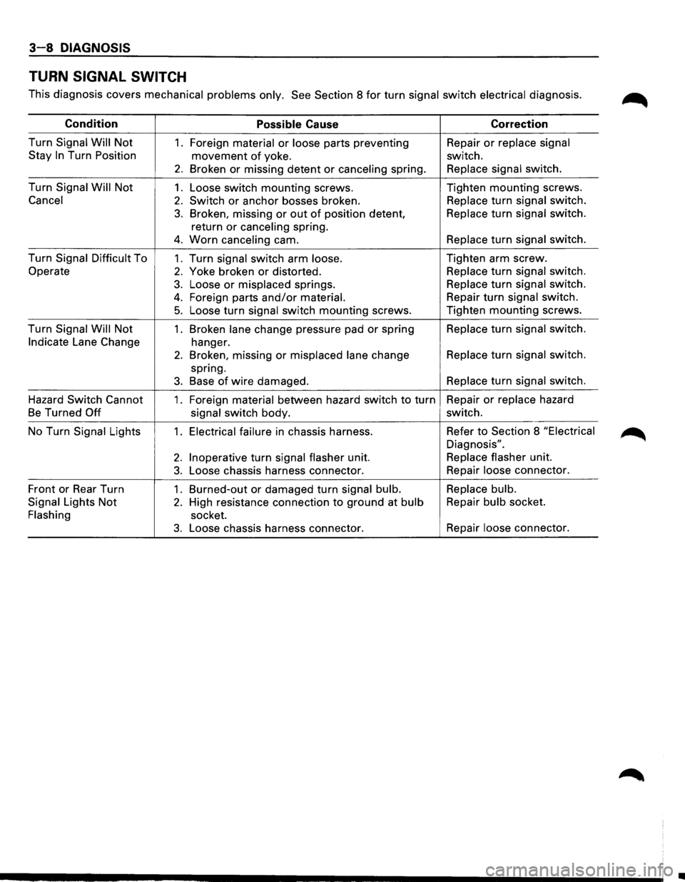
3-8 DIAGNOSIS
TURN SIGNAL SWITCH
This diagnosis covers mechanical problems only. See Section 8 for turn signal switch electrical diagnosis. ~
Condition Possible Cause Correction
Turn Signal
Will Not 1. Foreign material or loose parts preventing Repair or replace
signal
Stay
In Turn Position movement of yoke. switch.
2. Broken or missing detent or canceling spring. Replace
signal switch.
Turn Signal
Will Not 1. Loose switch mounting screws. Tighten mounting screws.
Cancel
2. Switch or anchor bosses broken. Replace
turn signal switch.
3. Broken, missing or out of position detent, Replace
turn signal switch.
return
or canceling spring.
4. Worn canceling cam. Replace
turn signal switch.
Turn Signal Difficult To
1. Turn signal switch arm loose. Tighten
arm screw.
Operate
2. Yoke broken or distorted. Replace
turn signal switch.
3. Loose or misplaced springs. Replace
turn signal switch.
4. Foreign parts and/or material. Repair
turn signal switch.
5. Loose turn signal switch mounting screws. Tighten mounting screws.
Turn Signal Will Not
1 . Broken lane change pressure pad or spring Replace
turn signal switch.
Indicate Lane Change
hanger.
2. Broken, missing or misplaced lane change Replace
turn signal switch.
spring.
3. Base of wire damaged. Replace
turn signal switch.
Hazard Switch Cannot
1. Foreign material between hazard switch to turn Repair
or replace hazard
Be Turned Off
signal switch body. switch.
No Turn Signal Lights
1. Electrical failure in chassis harness. Refer to Section
8 "Electrical
Diagnosis".
2. Inoperative turn signal flasher unit. Replace
flasher unit.
3. Loose chassis harness connector. Repair
loose connector.
Front or Rear Turn
1. Burned-out or damaged turn signal bulb. Replace
bulb.
Signal Lights
Not 2. High resistance connection to ground at bulb Repair
bulb socket.
Flashing socket.
3. Loose chassis harness connector. Repair
loose connector.
•
Page 329 of 1928
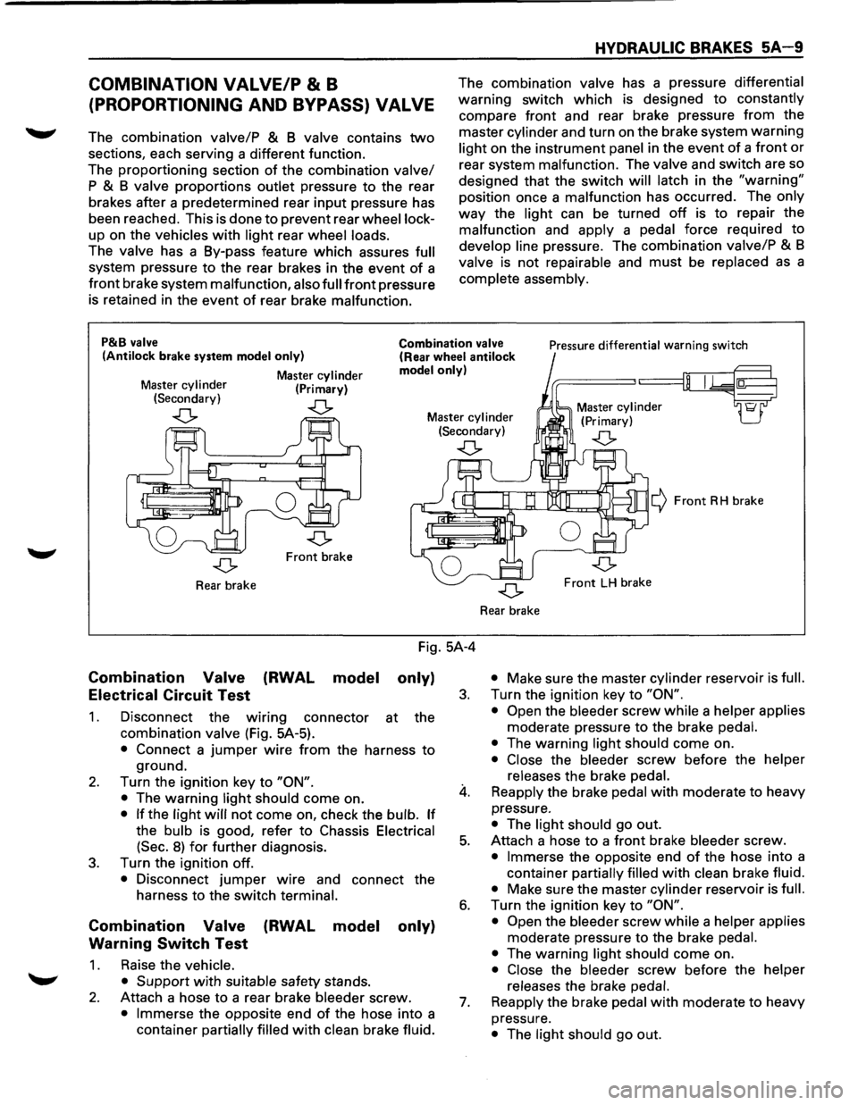
COMBINATION VALVE/P & B
(PROPORTIONING AND BYPASS) VALVE
The combination valve/P & B valve contains two
sections, each serving a different function.
The proportioning section
of the combination valve/
P & B valve proportions outlet pressure to the rear
brakes after a predetermined rear
input pressure has
been reached. This is done to prevent rear
wheel lock
up on the vehicles with light rear wheel loads.
The valve has a By-pass feature which assures full
system pressure to the rear brakes in the event of a
front brake system malfunction, also full front pressure
is retained in the event
of rear brake malfunction.
HYDRAULIC BRAKES 5A 9
The combination valve has a pressure differential
warning switch which is designed to constantly
compare front and rear brake pressure
from the
master
cylinder and turn on the brake system warning
light on the instrument panel in the event of a front or
rear system malfunction. The valve and switch are so
designed that the switch
will latch in the "warning"
position once a malfunction has occurred. The only
way the light can be turned off is to repair the
malfunction and
apply a pedal force required to
develop line pressure. The combination valve/P & B
valve is not repairable and must be replaced as a
complete assembly.
P&B valve
(Antilock brake system model only)
Master cylinder (Primary)
Combination valve (Rear wheel antilock model only)
Pressure differential warning switch
Master
cylinder (Secondary)
..(> ..(> Master cylinder (Secondary) Master
cylinder
(Primary)
..(> ..(>
Front brake
Rear brake
Combination Valve
Electrical Circuit Test (RWAL
model
Fig. 5A-4
only)
1.
2.
3.
Disconnect the wmng connector at the
combination
valve (Fig. 5A-5).
• Connect a jumper wire from the harness to
ground.
Turn the ignition key to
"ON".
•
The warning light should come on.
• If the light will not come on, check the bulb. If
the bulb is good, refer to Chassis Electrical
(Sec.
8) for further diagnosis.
Turn the ignition off.
• Disconnect jumper wire and connect the
harness to the switch
terminal.
Combination Valve (RWAL model only)
Warning
Switch Test
1. Raise the vehicle.
• Support
with suitable safety stands.
2. Attach a hose to a rear brake bleeder screw.
• Immerse the opposite end of the hose into a
container
partially filled with clean brake fluid.
3.
4.
5.
6.
7.
¢ Front RH brake
Front LH brake
Rear brake
• Make sure the master cylinder reservoir is full.
Turn the ignition key to "ON".
• Open
the bleeder screw while a helper applies
moderate pressure to the brake pedal.
•
The warning light should come on.
• Close the bleeder screw before the helper
releases
the brake pedal.
Reapply the brake pedal with moderate to heavy
pressure.
• The light should go out.
Attach a hose
to a front brake bleeder screw.
• Immerse the opposite end of the hose into a
container
partially filled with clean brake fluid.
• Make sure the master cylinder reservoir is full.
Turn the ignition key to "ON".
• Open
the bleeder screw while a helper applies
moderate pressure to the brake pedal.
•
The warning light should come on.
• Close the bleeder screw before the helper
releases
the brake pedal.
Reapply
the brake pedal with moderate to heavy
pressure.
• The light should go out.
Page 369 of 1928
REAR WHEEL ANTILOCK BRAKE SYSTEM 5A3-1
SECTION 5A3
REAR WHEEL ANTILOCK BRAKE SYSTEM
(RWAL}
w CAUTION:
• All brake attaching fasteners are an important attaching part in that they could affect performance of vital
parts and systems, and/or could result in major repair expense. They must be replaced with one of the same
part
number or with an equivalent part if replacement becomes necessary. Do not use replacement parts of
lesser quality or substitute design. Torque values must be used as specified during reassembly to assure
proper retention of these parts.
CONTENTS
Introduction . . . . . . . . . . . . . . . . . . . . . . . . . 5A3· 1
General Description . .
. . . . . . . . . . . . . . .
5A3· 1
Rear
Wheel Antilock (RWAL) Control
Parts Location . .
. . . . . . . . . . . . . . . . .
5A3· 5
System Diagram . .
. . . . . . . . . . . . . . . . . . . .
5A3· 6
Rear
Wheel Antilock (RWAL) System
Diagnostics . .
. . . . . . . . . . . . . . . . . . . . . .
5A3· 7
On-Vehicle Service . .
. . . . . . . . . . . . . . . . .
5A3·38
RWAL Electronic Brake Control
Module (EBCM) Replacement ....... 5A3-38
Antilock
(Isolation/Dump) Valve
Replacement ..................... 5A3-39
Speed Sensor Replacement
.......... 5A3-40
Main Data and Specifications ........... 5A3-41
Torque Specifications
............... 5A3-41
INTRODUCTION
This section deals with the complete diagnosis and
services
for vehicles equipped with rear wheel
antilock.
For service information regarding all other
components
of the brake system, refer to "Hydraulic
Brakes"
(Sec. SA), "Brake Booster System" (Sec. SA 1)
or "Disc Brakes" (Sec. SA2) of this Manual.
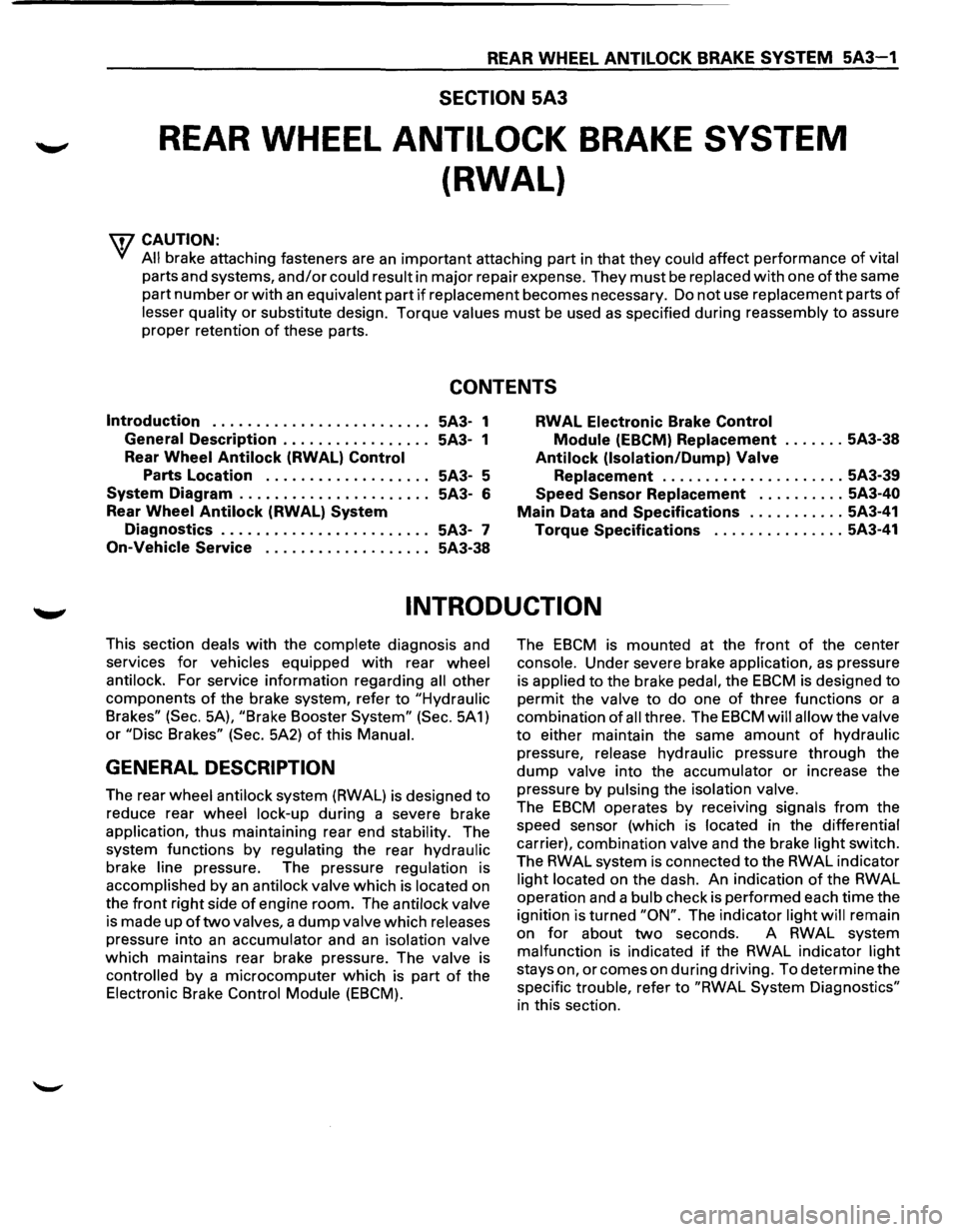
GENERAL DESCRIPTION
The rear wheel anti lock system (RWAL) is designed to
reduce rear wheel lock-up during a severe brake
application,
thus maintaining rear end stability. The
system functions
by regulating the rear hydraulic
brake line pressure. The pressure regulation is
accomplished
by an anti lock valve which is located on
the
front right side of engine room. The anti lock valve
is made up of two valves, a dump valve which releases
pressure into an accumulator and an isolation valve
which maintains rear brake pressure. The valve is
controlled
by a microcomputer which is part of the
Electronic Brake Control Module (EBCM). The
EBCM is mounted at the
front of the center
console. Under severe brake application, as pressure
is
applied to the brake pedal, the EBCM is designed to
permit the valve to do one of three functions or a
combination
of all three. The EBCM will allow the valve
to either maintain the same amount of hydraulic
pressure, release hydraulic pressure through the
dump valve into the accumulator or increase the
pressure by
pulsing the isolation valve.
The EBCM operates by receiving signals from the
speed sensor (which
is located in the differential
carrier), combination
valve and the brake light switch.
The RWAL system is connected
to the RWAL indicator
light located on the dash. An indication of the RWAL
operation and a
bulb check is performed each time the
ignition is turned
"ON". The indicator light will remain
on
for about two seconds. A RWAL system
malfunction is indicated if the RWAL indicator light
stays on, or comes on during driving. To determine the
specific
trouble, refer to "RWAL System Diagnostics"
in this section.
Page 376 of 1928
5A3-8 REAR WHEEL ANTILOCK BRAKE SYSTEM
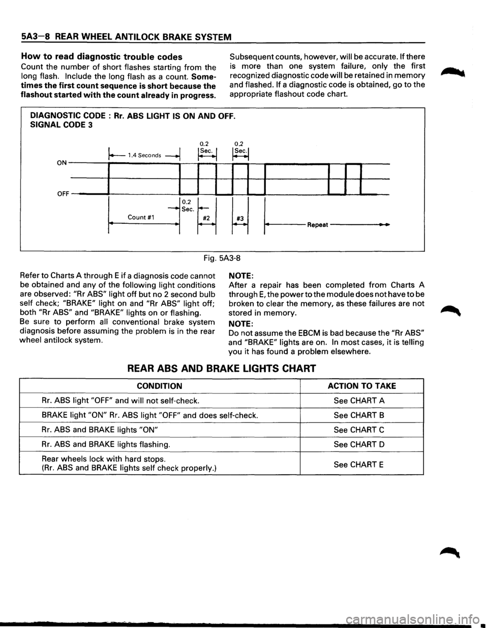
How to read diagnostic trouble codes
Count the number of short flashes starting from the
long flash. Include the long flash as a count. Some
times the first count sequence is short because the
flashout started with the count already in progress.
Subsequent counts, however, will be accurate. If there
is more than one system
failure, only the first
recognized diagnostic code
will be retained in memory
and flashed. If a diagnostic code is obtained, go to the
appropriate
flashout code chart.
DIAGNOSTIC CODE : Rr. ABS LIGHT IS ON AND OFF.
SIGNAL CODE 3
0.2 0.2 I I !Sec. I !Sec.! r--1.4 Seconds --+j ~ t--1
ON-------,~-----------,--~--~~~-r--?-----------~--r--r-----
OFF ~' ----L-1--'-----11 IL....-l.-1 ~I I ______..l__.__l ..____I
0.2~ ~ ~
-Sec.
Count #1 #2 #3 r----~ Repeat---
Fig. 5A3-8
Refer
to Charts A through E if a diagnosis code cannot
be obtained and any
of the following light conditions
are observed:
"Rr ABS" light off but no 2 second bulb
self
check; "BRAKE" light on and "Rr ABS" light off;
both
"Rr ABS" and "BRAKE" lights on or flashing.
Be sure to perform all conventional brake system
diagnosis before assuming the
problem is in the rear
wheel antilock system.
NOTE:
After a repair has been completed from Charts A
through
E, the power to the module does not have to be
broken to
clear the memory, as these failures are not
stored in memory.
NOTE:
Do not assume the EBCM is bad because the "Rr ABS"
and "BRAKE" lights are on. In most cases, it is telling
you it has found a problem elsewhere.
REAR ABS AND BRAKE LIGHTS CHART
CONDITION ACTION TO TAKE
Rr. ABS light "OFF" and will not self-check.
See CHART A
BRAKE light "ON" Rr. ABS light "OFF" and does self-check.
See CHART B
Rr. ABS and BRAKE lights "ON"
See CHART C
Rr. ABS and BRAKE lights flashing.
See CHART D
Rear
wheels lock with hard stops. See CHART E (Rr. ABS and BRAKE lights self check properly.)
Page 378 of 1928
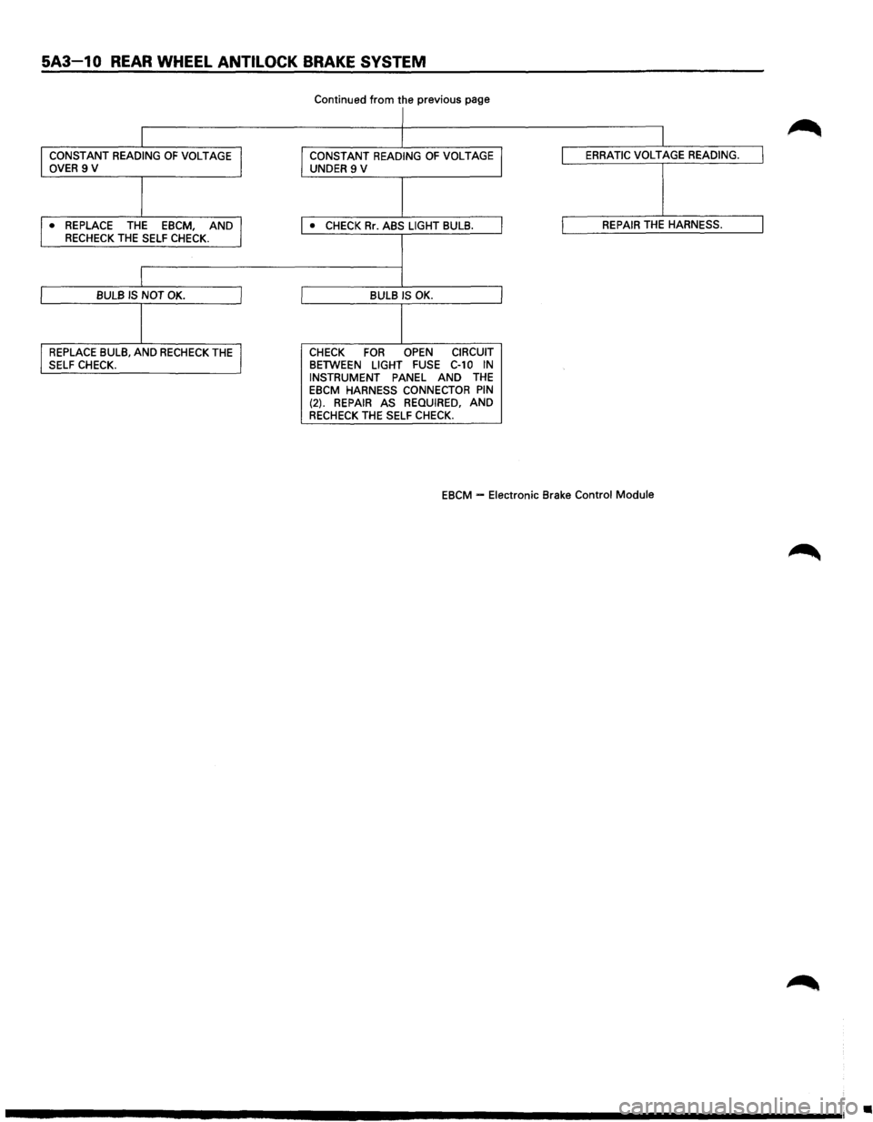
5A3-1 0 REAR WHEEL ANTI LOCK BRAKE SYSTEM
Continued from the previous page
I
I
I CONSTANT READING OF VOLTAGE J CONSTANT READING OF VOLTAGE I ERRATIC VOLTAGE READING. I OVER 9 V
UNDER 9 V
I ,. REPLACE THE EBCM, AND I • CHECK Rr. ABS LIGHT BULB. I REPAIR THE HARNESS. I RECHECK THE SELF CHECK.
I
I BULB IS NOT OK. I BULB IS OK.
1 I REPLACE BULB, AND RECHECK THE J CHECK FOR OPEN CIRCUIT
SELF CHECK. BETWEEN LIGHT FUSE C-10 IN INSTRUMENT PANEL AND THE EBCM HARNESS CONNECTOR PIN (2). REPAIR AS REQUIRED, AND RECHECK THE SELF CHECK.
EBCM
-Electronic Brake Control Module
•
Page 403 of 1928
REAR WHEEL ANTILOCK BRAKE SYSTEM 5A3-35
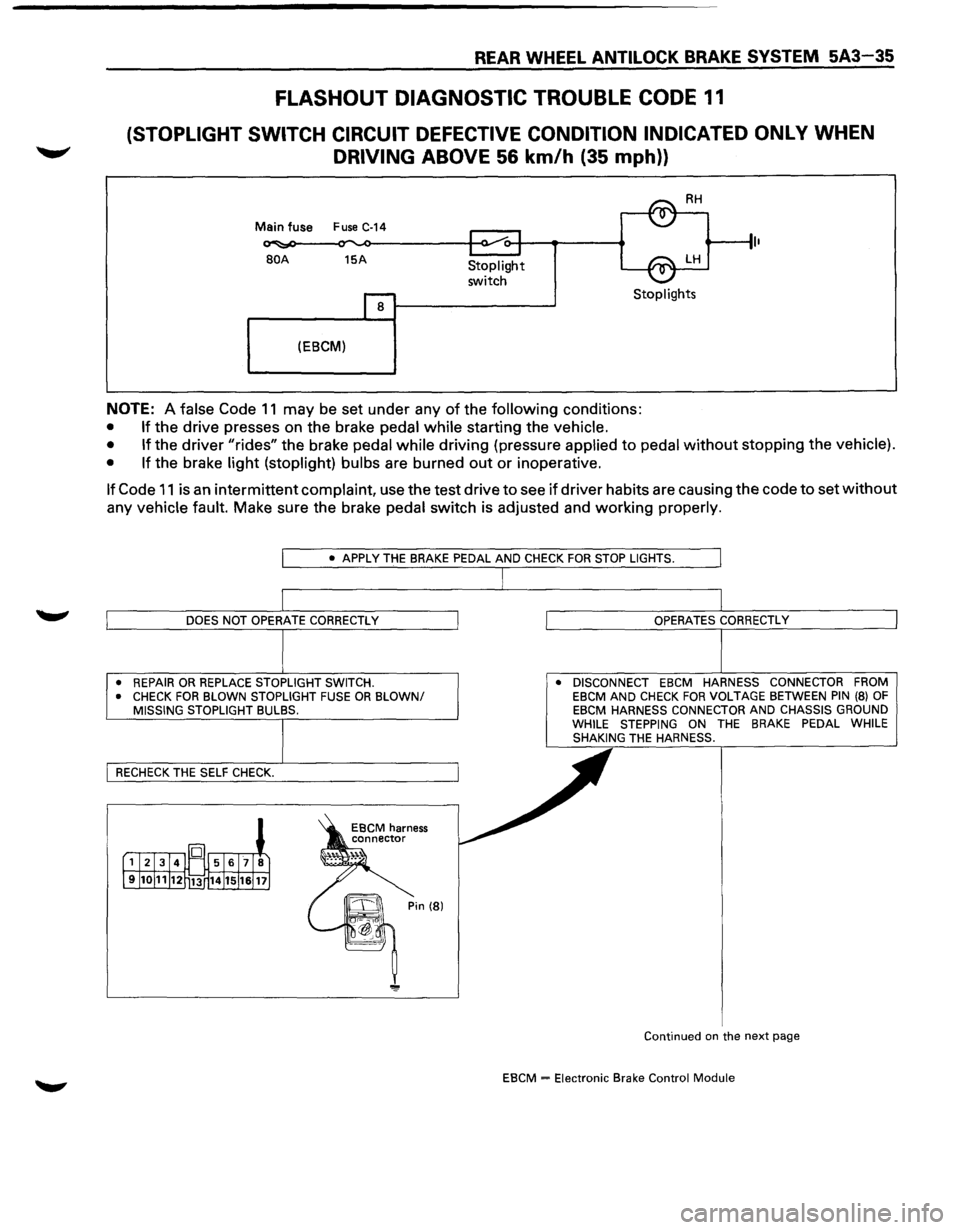
FLASHOUT DIAGNOSTIC TROUBLE CODE 11
(STOPLIGHT SWITCH CIRCUIT DEFECTIVE CONDITION INDICATED ONLY WHEN
DRIVING ABOVE 56 km/h (35 mph))
Main fuse Fuse C-14
BOA 15A
8
(EBCM)
Stoplight
switch Stoplights
NOTE: A false Code 11 may be set under any of the following conditions:
• If the drive presses on the brake pedal while starting the vehicle.
• If
the driver "rides" the brake pedal while driving (pressure applied to pedal without stopping the vehicle).
• If
the brake light (stoplight) bulbs are burned out or inoperative.
If Code 11 is an intermittent complaint, use the test drive to see if driver habits are causing the code to set without
any vehicle fault. Make sure the brake pedal switch is adjusted and working properly.
• REPAIR OR REPLACE STOPLIGHT SWITCH.
• CHECK FOR BLOWN STOPLIGHT FUSE OR BLOWN/ MISSING STOPLIGHT BULBS. •
DISCONNECT EBCM HARNESS CONNECTOR FROM
EBCM AND CHECK FOR VOLTAGE BETWEEN PIN (8) OF EBCM HARNESS CONNECTOR AND CHASSIS GROUND
WHILE STEPPING ON THE BRAKE PEDAL WHILE
SHAKING THE HARNESS.
Continued
on the next page
EBCM = Electronic Brake Control Module