bulb ISUZU TROOPER 1995 Owner's Manual
[x] Cancel search | Manufacturer: ISUZU, Model Year: 1995, Model line: TROOPER, Model: ISUZU TROOPER 1995Pages: 1928
Page 1209 of 1928
CHASSIS ELECTRICAL 8-19
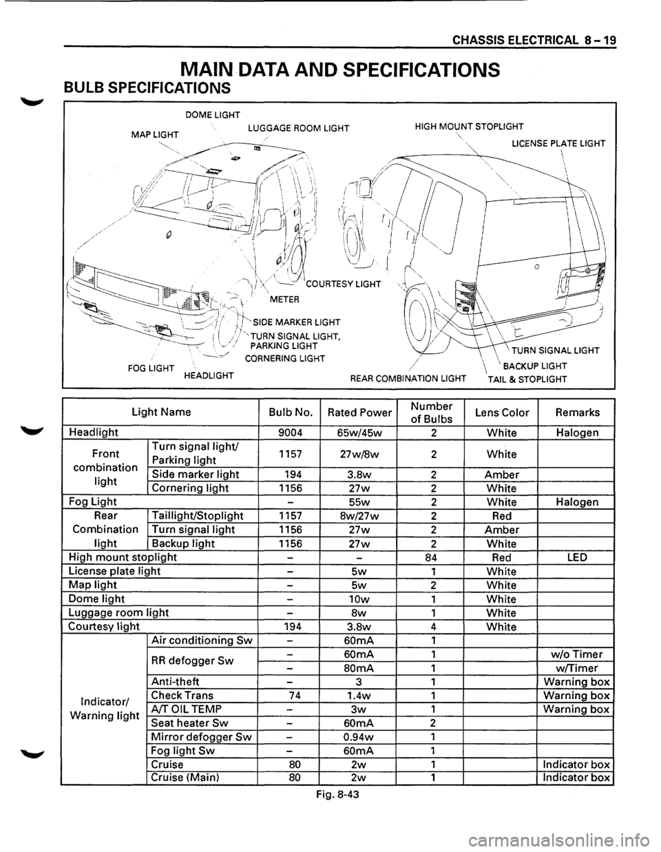
MAIN DATA AND SPECIFICATIONS
BULB SPECIFICATIONS
DOME LIGHT
MAP LIGHT LUGGAGE ROOM LIGHT HIGH MOUNT STOPLIGHT
FOG LIGHT HEADLIGHT
Light Name
Bulb No.
Headlight
9004
Front Turn
signal light/ 1157 Parking light combination Side marker light 194 light Cornering light 1156
Fog Light
-
Rear Taillight/Stoplight 1157
Combination Turn signal
light 1156
light Backup light 1156
High
mount stoplight -
License plate light -
Map light -
Dome light -
Luggage room light -
Courtesy light 194
Air conditioning Sw -
-
RR defogger Sw -
Anti-theft -
Indicator/ Check
Trans 74
Warning light A/TOIL TEMP -
Seat heater Sw -
Mirror defogger Sw -
Fog light Sw -
Cruise 80
Cruise (Main) 80
""·
,/
REAR COMBINATION LIGHT
Rated Power Number
of Bulbs
65w/45w 2
27w/8w 2
3.8w 2
27w 2
55w 2
8w/27w 2
27w 2
27w 2
-84
5w 1
5w 2
10w 1
8w 1
3.8w 4
60mA 1
60mA 1
SOmA 1
3 1
1.4w 1
3w 1
60mA 2
0.94w 1
60mA 1
2w 1
2w 1
Fig. 8-43
\BACKUP LIGHT
TAIL & STOPLIGHT
Lens Color Remarks
White Halogen
White
Amber
White
White Halogen
Red
Amber
White
Red LED
White
White
White
White
White
w/oTimer
w/Timer
Warning box
Warning box
Warning box
Indicator box
Indicator box
Page 1210 of 1928
8-20 CHASSIS ELECTRICAL
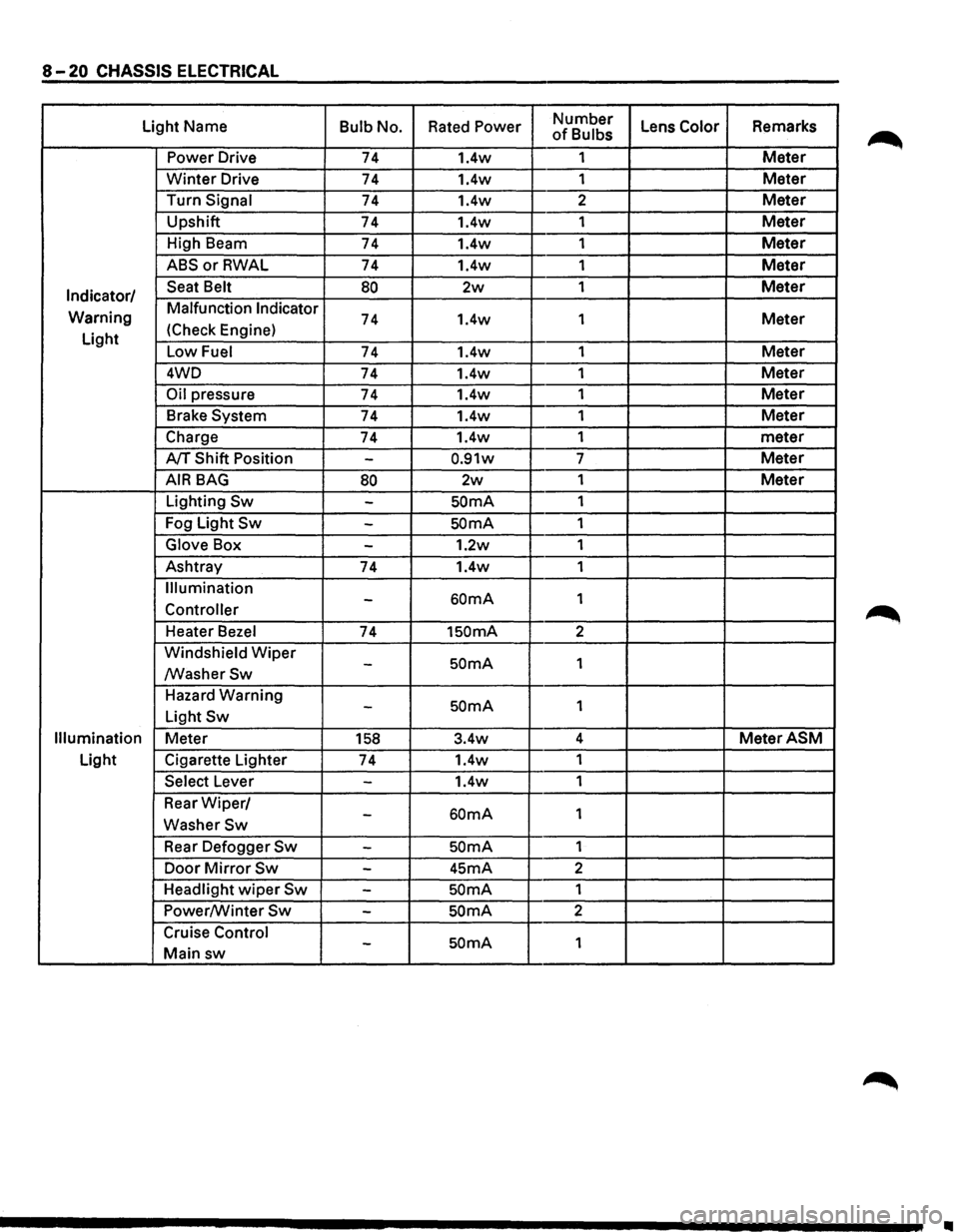
Light Name Bulb No. Rated Power Number Lens Color Remarks of Bulbs
Power Drive 74 1.4w 1
Meter
Winter Drive 74 1.4w
1 Meter
Turn Signal 74 1.4w 2 Meter
Upshift
74 1.4w 1 Meter
High Beam
74 1.4w 1 Meter
ABSorRWAL 74 1.4w 1 Meter
Indicator/ Seat Belt 80 2w 1 Meter
Warning Malfunction Indicator 74 1.4w
1 Meter
Light (Check
Engine)
Low Fuel 74 1.4w 1 Meter
4WD
74 1.4w 1 Meter
Oil pressure 74 1.4w 1 Meter
Brake System 74 1.4w 1 Meter
Charge 74 1.4w 1
meter
A/T Shift Position -0.91w 7 Meter
AIR BAG 80 2w 1 Meter
Lighting Sw -SOmA 1
Fog Light
Sw -SOmA 1
Glove Box -1.2w 1
Ashtray
74 1.4w 1
Illumination
60mA 1 -Controller
Heater Bezel 74 1SOmA 2
Windshield
Wiper SOmA 1 -/WasherSw
Hazard Warning SOmA 1 -Light Sw
Illumination Meter 158 3.4w 4 MeterASM
Light
Cigarette Lighter
74 1.4w
1
Select Lever -1.4w 1
Rear
Wiper/ 60mA 1 -WasherSw
Rear Defogger Sw -SOmA 1
Door
Mirror Sw -45mA 2
Headlight
wiper Sw -SOmA 1
Power/Winter
Sw -SOmA 2
Cruise Control
SOmA 1 -Main sw
II
Page 1234 of 1928
8-44 CHASSIS ELECTRICAL
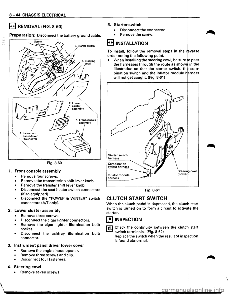
B REMOVAL (FIG. 8-60)
Preparation: Disconnect the battery ground cable.
5. Starter switch
Fig. 8-60
1. Front console assembly
• Remove four screws.
• Remove the transmission shift lever knob.
• Remove the transfer shift lever knob.
• Disconnect the seat heater switch connectors
(If so equipped).
• Disconnect the "POWER & WINTER" switch
connectors
(A/T only).
2. Lower cluster assembly
• Remove three screws.
• Disconnect the cigar lighter connectors.
• Remove the cigar lighter illumination bulb
socket.
• Disconnect the ashtray illumination bulb
connector.
3. Instrument panel driver lower cover
• Remove the engine hood opener.
• Remove three screws and clip.
• Disconnect four fasteners.
4. Steering cowl
• Remove seven screws .
5. Starter switch
• Disconnect the connector.
• Remove the screw.
B INSTALLATION
To install, follow the removal steps in the everse
order noting the
following point.
1. When installing the steering cowl, be sure o pass
the harnesses through the route as
show in the
illustration so that the starter switch, th com
bination switch and the inflator
module
will not get caught. (Fig. 8-61)
Starter switch
harness
Fig. 8-61
CLUTCH START SWITCH
cowl
When the clutch pedal is depressed, the clute start
switch is turned on
to form a circuit to activ e the
starter.
~ INSPECTION
1 til!. I Check the continuity between the clute start
switch terminals. (Fig. 8-62)
Replace the switch when the result
of insp ction
is found abnormal.
'
Page 1252 of 1928
8-62 CHASSIS ELECTRICAL
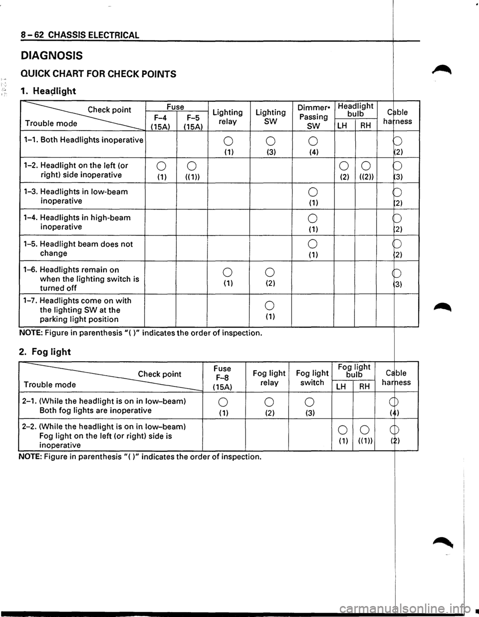
DIAGNOSIS
QUICK CHART FOR CHECK POINTS ~ )-; '. ·'·• 1. Heaplight 1:·
~
Fuse Lighting Lighting Dimmer• Headlight c ~ble Passing bulb F-4
F-5 relay sw ha ness
T
(15A) (15A) sw LH RH
1-1. Both Headlights inoperative 0 0 0 b (1) (3) (4) 2)
1-2. Headlight on
the left (or 0 0 0
0 b right) side inoperative (1) ((1)) (2) ((2)) 3)
1-3. Headlights in low-beam 0 b inoperative (1) 2)
1-4. Headlights in high-beam 0 b inoperative
(1) 2)
1-5. Headlight beam does not 0 p
change (1) 2)
1-6. Headlights remain on 0 0 b when the lighting switch is
( 1) (2) 3) turned off
1-7. Headlights come on with 0 ~ the lighting SW at the
parking light position (1)
NOTE: Figure in parenthesis"( )" indicates the order of inspection.
2. Fog light
~
Fuse
Fog light Fog light Fog light Cc ble F-8 bulb
(15A) relay switch LH RH har ness Tr
2-1. (While the headlight is on in low-beam) 0 0 0 c ~ Both
fog lights are inoperative (1) (2) (3) ( )
2-2. (While the headlight is
on in low-beam) 0 0 CD Fog light on the left (or right) side is
( 1) ( ( 1)) ( ) inoperative
NOTE: Figure
in parenthesis"()" indicates the order of inspection.
~ -'
..
Page 1254 of 1928
8 -64 CHASSIS ELECTRICAL
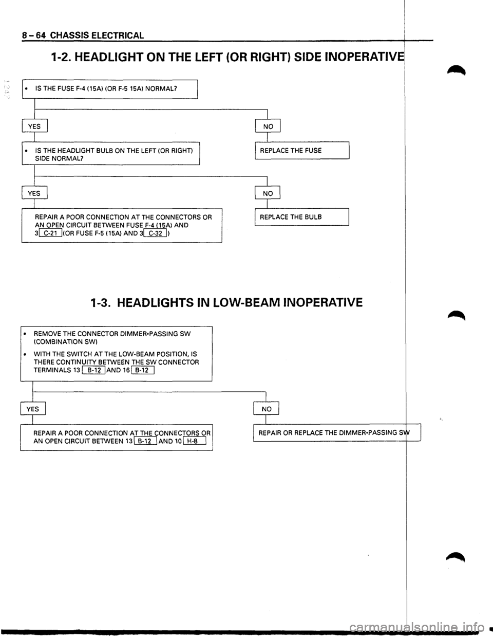
1-2. HEADLIGHT ON THE LEFT (OR RIGHT) SIDE INOPERATIVE
• IS THE FUSE F-4 (15A) (OR F-5 15Al NORMAL?
I
I
YES I
I
• IS THE HEADLIGHT BULB ON THE LEFT (OR RIGHT)
SIDE NORMAL?
I
I
YES I
I
I
REPAIR A POOR CONNECTION AT THE CONNECTORS OR
AN OPEN CIRCUIT BETWEEN FUSE F-4 (15Al AND
3~(0R FUSE F-5 115Al AND 3WUI
I
I NO I
I
I REPLACE THE FUSE
I
I NO I
I
I REPLACE THE BULB
I
I
1-3. HEADLIGHTS IN LOW-BEAM INOPERATIVE
• REMOVE THE CONNECTOR DIMMER•PASSING SW (COMBINATION SW)
• WITH
THE SWITCH AT THE LOW-BEAM POSITION, IS THERE CONTINUITY BETWEEN THE SW CONNECTOR
TERMINALS
13[[I[jAND 16[[1[]
I
I
YES I
I
REPAIR A POOR CONNECTION AT THE CONNECTORS OR
AN OPEN CIRCUIT BETWEEN 13[[ll]AND 10~
I
I NO I
I
I REPAIR OR REPLACE THE DIMMER•PASSING S1tJ I
Page 1258 of 1928
8-68 CHASSIS ELECTRICAL
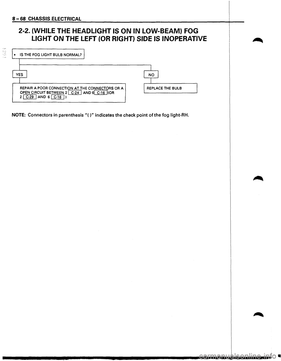
2-2. (WHILE THE HEADLIGHT IS ON IN LOW-BEAM) FOG
LIGHT
ON THE LEFT (OR RIGHT) SIDE IS INOPERATIVE
• IS THE FOG LIGHT BULB NORMAL?
I
I
YES I
I
REPAIR A POOR CONNECTION AT THE CONNECTORS OR A OPEN CIRCUIT BETWEEN 2 WU AND 6~(0R 2~AND 6[f}[]l
I
I NO I
I
l REPLACE THE BULB
NOTE: Connectors in parenthesis"()" indicates the check point of the fog light-RH.
I
•
Page 1261 of 1928
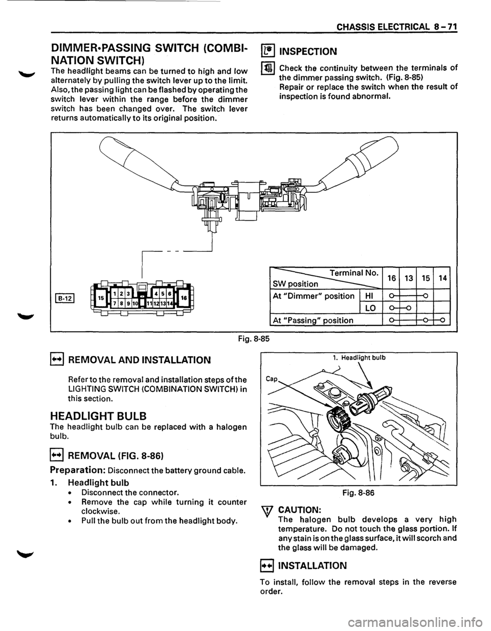
DIMMER·PASSING SWITCH (COMBI
NATION SWITCH)
The headlight beams can be turned to high and low
alternately by pulling the switch lever up to the limit.
Also, the passing light can be flashed by operating the
switch lever within the range before the dimmer
switch has been changed over. The switch lever
returns automatically to its original position.
CHASSIS ELECTRICAL 8 -71
~ INSPECTION
lt!l Check the continuity between the terminals of
the dimmer passing switch. (Fig. 8-85)
Repair
or replace the switch when the result of
inspection is found abnormal.
~· s 16 13 15 14
At "Dimmer" position HI ~ ~ -
LO o-f-o
At "Passing" position ~ ~ ~
Fig.
8-85
E] REMOVAL AND INSTALLATION
Refer to the removal and installation steps oft he
LIGHTING SWITCH (COMBINATION SWITCH) in
this section.
HEADLIGHT BULB
The headlight bulb can be replaced with a halogen
bulb.
E] REMOVAL (FIG. 8-86)
Preparation: Disconnect the battery ground cable.
1. Headlight bulb
• Disconnect the connector.
• Remove the cap while turning it counter
clockwise.
• Pull the bulb out from the headlight body.
1. Headlight bulb
Fig. 8-86
W CAUTION:
The halogen bulb develops a very high
temperature. Do not touch the glass portion. If
any stain is on the glass surface, it will scorch and
the glass will be damaged.
B INSTALLATION
To install, follow the removal steps in the reverse
order.
Page 1262 of 1928
8 -72 CHASSIS ELECTRICAL
HEADLIGHT
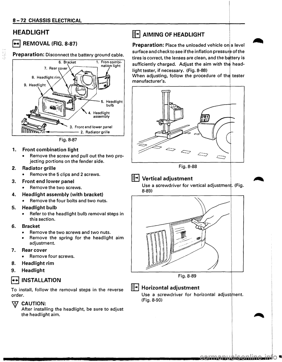
E) REMOVAL (FIG. 8-87)
Preparation: Disconnect the battery ground cable.
Fig. 8-87
1. Front combination light
• Remove the screw and pull out the two pro
jecting
portions on the fender side.
2. Radiator grille
• Remove the 5 clips and 2 screws.
3. Front end lower panel
• Remove the two screws.
4. Headlight assembly (with bracket)
• Remove the four bolts and two nuts.
5. Headlight bulb
• Refer to the headlight bulb removal steps in
this section.
6. Bracket
• Remove the two screws and two nuts.
• Remove the spring for the headlight aim
adjustment.
7. Rear cover
• Remove four screws.
8. Headlight rim
9. Headlight
E3 INSTALLATION
To install, follow the removal steps in the reverse
order.
W CAUTION:
After installing the headlight, be sure to adjust
the headlight aim.
(E AIMING OF HEADLIGHT
Preparation: Place the unloaded vehicle on a level
surface and check to see ifthe inflation pressur oft he
tires is correct, the lenses are clean, and the b ttery is
sufficiently charged.
Adjust the aim with th head
light tester, if necessary. (fig. 8-88)
When adjusting,
follow the procedure of th tester
manufacturer's.
Fig. 8-88
1~1 .... 1 Vertical adjustment
Use a screwdriver for vertical adjustmen . (Fig.
8-89)
Fig. 8-89
m .... l Horizontal adjustment
Use a screwdriver for horizontal adjust ent.
(Fig.
8-90)
..
Page 1263 of 1928
CHASSIS ELECTRICAL 8-73
FOG LIGHT ASSEMBLY
~ I : I
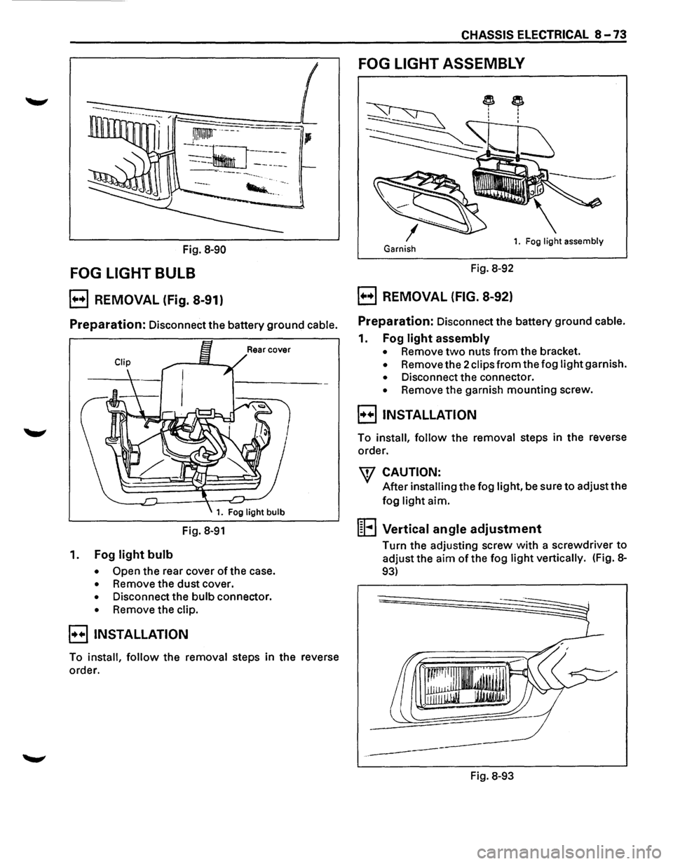
Fig. 8-90 Garnish 1. Fog light assembly
FOG LIGHT BULB Fig. 8-92
B REMOVAL (Fig. 8-91) B REMOVAL (FIG. 8-92)
Preparation: Disconnect the battery ground cable. Preparation: Disconnect the battery ground cable.
Fig. 8-91
1. Fog light bulb
• Open the rear cover of the case.
• Remove the dust cover.
• Disconnect the bulb connector.
• Remove the clip.
EJINSTALLATION
To install, follow the removal steps in the reverse
order.
1. Fog light assembly
• Remove two nuts from the bracket.
• Remove the 2 clips from the fog light garnish.
• Disconnect the connector.
• Remove the garnish mounting screw.
B INSTALLATION
To install, follow the removal steps in the reverse
order.
\V CAUTION:
After installing the fog light, be sure to adjust the
fog light aim.
1~1 ... 1 Vertical angle adjustment
Turn the adjusting screw with a screwdriver to
adjust the aim of the fog light vertically. (Fig. 8-
93)
1r~~·~··.l J.li' . WlliJ
-'I IJIJJ
---
-------
Fig. 8-93
Page 1264 of 1928
8-74 CHASSIS ELECTRICAL
FOG LIGHT SWITCH
~ INSPECTION
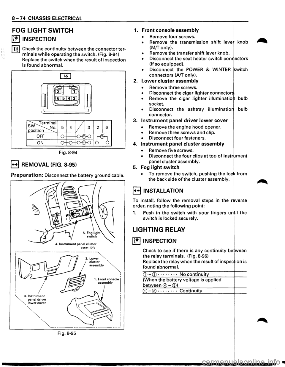
I tgj Check the continuity between the connector ter
minals
while operating the switch. (Fig. 8-94)
Replace the switch when the result of inspection
is found abnormal.
ru~
IT
2 [II
161514131
c-
Fig. 8-94
B REMOVAL (FIG. 8-95)
TI ';
Preparation: Disconnect the battery ground cable.
Fig.
8-95
I I 1. Front console I assembly
1. Front console assembly
• Remove four screws.
• Remove the transmission shift leve knob
(M!r only).
• Remove the transfer shift lever knob.
• Disconnect the seat heater switch con ectors
(If so equipped).
• Disconnect the POWER & WINTER switch
connectors
(A/T only).
2.
Lower cluster assembly
• Remove three screws.
• Disconnect the cigar lighter connector .
• Remove the cigar lighter illuminatio bulb
socket.
• Disconnect the ashtray illuminatio bulb
connector.
3.
Instrument panel driver lower cover
• Remove the engine hood opener.
• Remove three screws and clip.
• Disconnect four fasteners.
4.
Instrument panel cluster assembly
• Remove five screws.
• Disconnect the four clips at top of instr ment
panel cluster assembly.
5. Fog
light switch
• To remove the switch, pushing the loc from
the back side of the cluster assembly.
B INSTALLATION
To install, follow the removal steps in the r verse
order, noting the
following point:
1. Push in the switch with your fingers un il the
switch is locked securely.
LIGHTING RELAY
~ INSPECTION
Check to see if there is any continuity be ween
the relay terminals. (Fig.
8-96)
Replace the relay when the result of in spec ion is
found abnormal.
CD-3 · · · · • · · · No continuit
(When the battery voltage is applied
between
4 -s)
•