bulb ISUZU TROOPER 1995 Repair Manual
[x] Cancel search | Manufacturer: ISUZU, Model Year: 1995, Model line: TROOPER, Model: ISUZU TROOPER 1995Pages: 1928
Page 1656 of 1928
9J-32 Supplemental Restraint System (SRS)
SRS DIAGNOSTIC SYSTEM CHECK
WARNING: TO AVOID DEPLOYMENT WHEN
TROUBLESHOOTING THE SRS, DO NOT USE
ELECTRICAL TEST EQUIPMENT SUCH AS A
BATTERY-POWERED OR AC-POWERED
VOLTMETER, OHMMETER, ETC., OR ANY TYPE OF
ELECTRICAL EQUIPMENT OTHER THAN THAT
SPECIFIED IN THIS MANUAL. DO NOT USE A
NON-POWERED PROBE TYPE TESTER.
INSTRUCTIONS IN THIS MANUAL MUST BE
FOLLOWED CAREFULLY, OTHERWISE PERSONAL
INJURY
MAY RESULT.
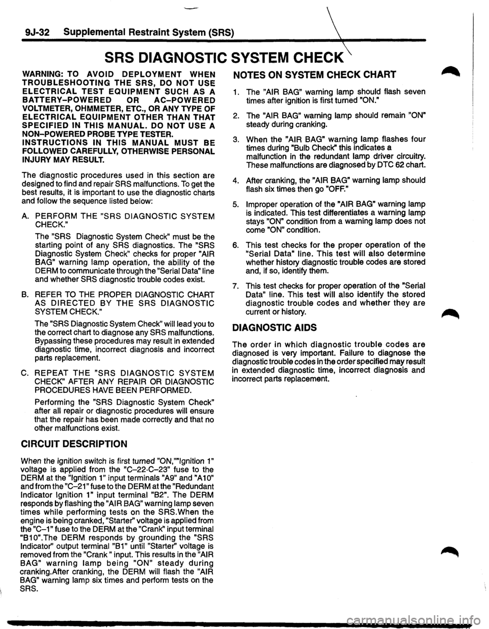
The diagnostic procedures used in this section are
designed to find and repair
SRS malfunctions. To get the
best results, it is important to use the diagnostic charts
and
follow the sequence listed below:
A. PERFORM THE "SRS DIAGNOSTIC SYSTEM
CHECK."
The "SRS Diagnostic System Check" must be the
starting point of any
SRS diagnostics. The "SRS
Diagnostic System Check" checks for proper "AIR
BAG"
warning lamp operation, the ability of the
DERM to communicate through the
"Serial Data" line
and whether SRS diagnostic trouble codes exist.
B. REFER TO THE PROPER DIAGNOSTIC CHART
AS
DIRECTED BY THE SRS DIAGNOSTIC
SYSTEM CHECK."
The "SRS Diagnostic System Check" will lead you to
the correct chart to diagnose any
SRS malfunctions.
Bypassing these procedures may result
in extended
diagnostic time, incorrect diagnosis and incorrect
parts replacement.
C. REPEAT THE "SRS DIAGNOSTIC SYSTEM
CHECK" AFTER ANY REPAIR OR DIAGNOSTIC
PROCEDURES HAVE
BEEN PERFORMED.
Performing
the "SRS Diagnostic System Check"
after all repair or diagnostic procedures will ensure
that the repair has been made correctly and that no
other malfunctions exist.
CIRCUIT DESCRIPTION
When the ignition switch is first turned "ON,""Ignition 1"
voltage is applied from the "C-22·C-23" fuse to the
DERM at the
"Ignition 1" input terminals "A9" and "A10"
and from the "C-21" fuse to the DERM at the "Redundant
Indicator Ignition 1" input terminal "B2". The DERM
responds by flashing the
"AIR BAG" warning lamp seven
times while performing tests on the
SRS.When the
engine is being cranked,
"Starter'' voltage is applied from
the
"C-1" fuse to the DERM at the "Crank" input terminal
"B10".The DERM responds by grounding the "SRS
Indicator"
output terminal "B 1" until "Starter" voltage is
removed from the "Crank" input. This results in the "AIR
BAG" warning lamp being "ON" steady during
cranking.After cranking, the DERM will flash the "AIR
BAG"
warning lamp six times and perform tests on the
SRS.
NOTES ON SYSTEM CHECK CHART ~
1. The "AIR BAG" warning lamp should flash seven
times after ignition is first turned
"ON."
2. The "AIR BAG" warning lamp should remain "ON"
steady during cranking.
3. When the "AIR BAG" warning lamp flashes four
times during
"Bulb Check" this indicates a
malfunction
in the redundant lamp driver circuitry.
These malfunctions are diagnosed by
DTC 62 chart.
4. After cranking, the "AIR BAG" warning lamp should
flash six times then go
"OFF."
5. Improper operation of the "AIR BAG" warning lamp
is indicated. This test differentiates a warning lamp
stays
"ON" condition from a warning lamp does not
come
"ON" condition.
6. This test checks for the proper operation of the
"Serial Data" line. This test will also determine
whether history diagnostic trouble codes are stored
and, if so, identify them.
7. This test checks for proper operation of the
"Serial
Data"
line. This test will also identify the stored
diagnostic trouble codes and
whether they are
current or history.
~
DIAGNOSTIC AIDS
The order in which diagnostic trouble codes are
diagnosed is very important. Failure to diagnose the
diagnostic trouble codes in the order specified may result
in extended diagnostic time, incorrect diagnosis and
incorrect parts replacement.
Page 1662 of 1928
9J-38-~tal Restraint System
TABLE C
"AIR BAG" WARNING LAMP DOES NOT COME "ON"
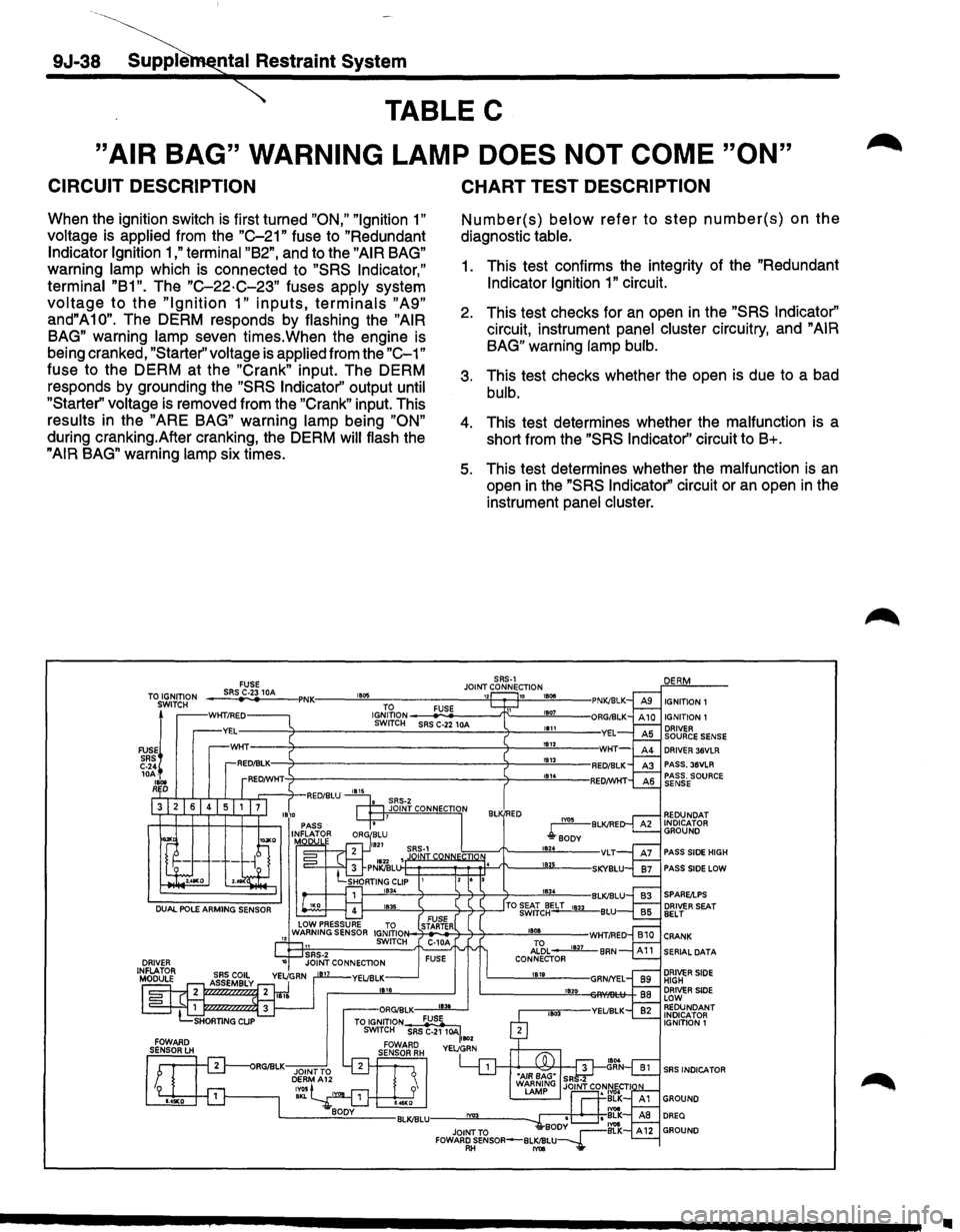
CIRCUIT DESCRIPTION
When the ignition switch is first turned "ON," "Ignition 1"
voltage is applied from the "C-21" fuse to "Redundant
Indicator Ignition 1 ,"terminal "B2", and to the "AIR BAG"
warning lamp which is connected to "SRS Indicator,"
terminal "B1".
The "C-22·C-23" fuses apply system
voltage to the "Ignition 1" inputs, terminals "A9"
and"A10". The DERM responds by flashing the "AIR
BAG"
warning lamp seven times.When the engine is
being cranked,
"Starter'' voltage is applied from the "C-1"
fuse to the DERM at the "Crank" input. The DERM
responds by grounding the
"SRS Indicator'' output until
"Starter" voltage
is removed from the "Crank" input. This
results in the "ARE BAG" warning lamp being "ON"
during cranking.After cranking, the DERM will flash the
"AIR BAG" warning lamp six times.
TO IGNITION
SWITCH
FUSEj
SRS C-24 10A-
1Bot RD
FUSE SRS C-23 10A ,. ..
CHART TEST DESCRIPTION
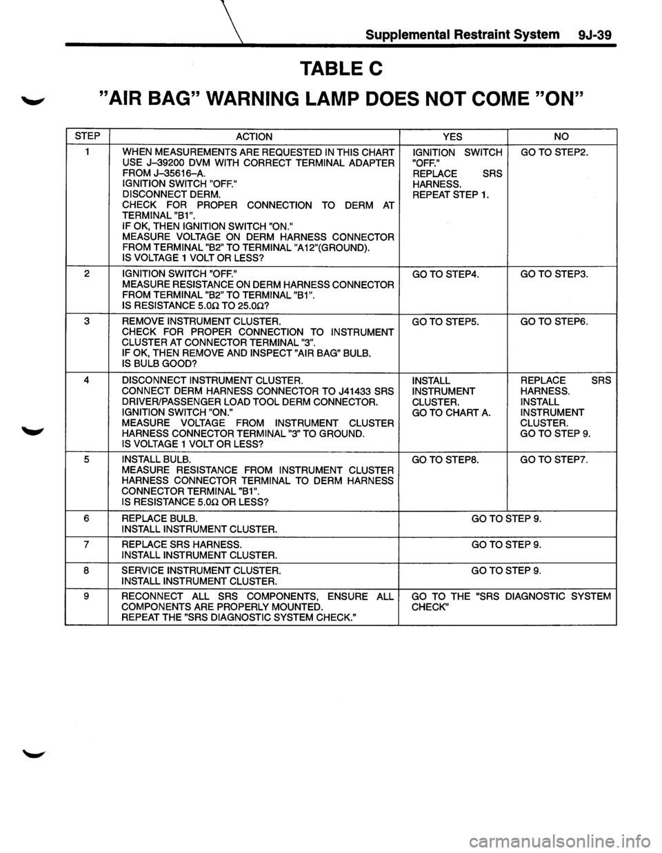
Number(s) below refer to step number(s) on the
diagnostic table.
1. This test confirms the integrity of the "Redundant
Indicator Ignition 1" circuit.
2. This test checks for an open in the "SRS Indicator"
circuit, instrument panel cluster circuitry, and "AIR
BAG"
warning lamp bulb.
3. This test checks whether the open is due to a bad
bulb.
4. This test determines whether the malfunction is a
short from the
"SRS Indicator'' circuit to B+.
5. This test determines whether the malfunction is an
open in the "SRS Indicator'' circuit or an open in the
instrument
panel cluster.
SRS-1 JOINT CONNECTION
1834
IGNITION 1 IGNITION 1 DRIVER SOURCE SENSE DRIVER 36VLR PASS. 36VLR
REDUNDAT
INDICATOR GROUND
PASS
SIDE HIGH
PASS
SIDE LOW
1---''""""'-------'l-----l--'1-~--'TO ~&'Jc~ELT 1833 BLU FUSE N-7-ST.,AR_TE.,_R+-'l---'1----"''"'"'-"---WHT/RED C-1 0A Al'6L ____.Jill_ BAN FUSE CONNECTOR 1819
1820
SERIAL DATA
DRIVER SIDE HIGH DRIVER SIDE LOW REDUNDANT INDICATOR
IGNITION 1
SRS INDICA TOR
•
Page 1663 of 1928
Supplemental Restraint System 9J-39
TABLE C
._, "AIR BAG" WARNING LAMP DOES NOT COME "ON"
STEP
ACTION YES NO
1
WHEN MEASUREMENTS ARE REQUESTED IN THIS CHART IGNITION SWITCH GOTOSTEP2. USE J-39200 DVM
WITH CORRECT TERMINAL ADAPTER "OFF."
FROM J-35616-A. REPLACE SRS
IGNITION SWITCH "OFF."
HARNESS.
DISCONNECT
DERM. REPEAT STEP 1. CHECK FOR PROPER CONNECTION TO DERM AT TERMINAL "B1 ".
IF OK, THEN IGNITION SWITCH "ON." MEASURE VOLTAGE ON DERM HARNESS CONNECTOR
FROM TERMINAL "B2" TO TERMINAL "A12"(GROUND).
IS VOLTAGE
1 VOLT OR LESS?
2 IGNITION SWITCH "OFF." GOTOSTEP4. GOTO STEP3.
MEASURE RESISTANCE ON DERM HARNESS CONNECTOR
FROM TERMINAL "B2" TO TERMINAL "B1".
IS RESISTANCE
5.0.Q TO 25.0.Q?
3 REMOVE INSTRUMENT CLUSTER. GOTOSTEP5. GOTOSTEP6. CHECK FOR PROPER CONNECTION TO
INSTRUMENT
CLUSTER AT CONNECTOR TERMINAL "3".
IF OK, THEN REMOVE AND INSPECT "AIR BAG" BULB. IS BULB GOOD?
4 DISCONNECT INSTRUMENT CLUSTER.
INSTALL REPLACE SRS
CONNECT DERM HARNESS CONNECTOR TO J41433 SRS
INSTRUMENT HARNESS.
DRIVER/PASSENGER LOAD TOOL
DERM CONNECTOR.
CLUSTER. INSTALL
IGNITION SWITCH "ON."
GO TO
CHART A. INSTRUMENT
MEASURE VOLTAGE FROM INSTRUMENT
CLUSTER CLUSTER.
HARNESS CONNECTOR TERMINAL "3" TO
GROUND. GOTOSTEP9. IS VOLTAGE 1 VOLT OR LESS?
5 INSTALL BULB. GOTO STEPS. GO
TO STEP?.
MEASURE RESISTANCE FROM INSTRUMENT CLUSTER
HARNESS CONNECTOR TERMINAL TO
DERM HARNESS
CONNECTOR TERMINAL "B1".
IS RESISTANCE 5.0n OR LESS?
6 REPLACE BULB. GOTOSTEP9. INSTALL INSTRUMENT CLUSTER.
7 REPLACE SRS HARNESS. GOTOSTEP9. INSTALL INSTRUMENT CLUSTER.
8 SERVICE INSTRUMENT CLUSTER. GOTOSTEP9. INSTALL INSTRUMENT CLUSTER.
9
RECONNECT ALL SRS COMPONENTS, ENSURE ALL GO TO THE "SRS DIAGNOSTIC SYSTEM
COMPONENTS ARE PROPERLY MOUNTED. CHECK" REPEAT THE "SRS DIAGNOSTIC SYSTEM CHECK."
Page 1668 of 1928
9J-44 Supplemental Restraint System
DTC 15
PASSENGER INITIATOR CIRCUIT RESISTANCE HIGH
CIRCUIT DESCRIPTION
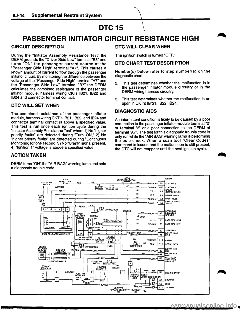
During the "Initiator Assembly Resistance Test" the
DERM grounds the
"Driver Side Low" terminal "BB" and
turns "ON" the passenger current source at the
"Passenger Side High" terminal "A7". This causes a
known amount of current to
flow through the passenger
initiator circuit. By monitoring the difference between the
voltage at the "Passenger Side High" terminal "A7" and
the "Passenger
Side Low" terminal "B7" the DERM
calculates the combined resistance of the passenger
inflator module, harness wiring CKTs IB21, IB22 and
IB24 and connector terminal contact.
DTC WILL SET WHEN
The combined resistance of the passenger inflator
module,
harness wiring CKT's IB21, IB22, and IB24 and
connector
terminal contact is above a specified value.
This test is run once each ignition cycle during the
"Initiator Assembly Resistance Tesf' when: 1) No "higher
priority faults" are detected during "Turn-ON," 2) No
"higher priority faults" are detected during "Continuous
Monitoring for one second, 3) No "Crank" signal present,
4) "Ignition 1" voltage is above a specified value.
ACTION TAKEN
DERM turns "ON" the "AIR BAG" warning lamp and sets
a diagnostic
trouble code.
DTC WILL CLEAR WHEN
The ignition switch is turned "OFF."
DTC CHART TEST DESCRIPTION
Number(s) below refer to step number(s) on the
diagnostic chart.
2. This test determines whether the malfunction is in
the passenger inflator module circuitry or in the
DERM wiring harness circuitry.
3. This test determines whether the malfunction is an
open in CKT's IB"21, IB22, IB24.
DIAGNOSTIC AIDS
An intermittent condition is likely to be caused by a poor
connection to the passenger
inflator module terminal "2"
or terminal "3" or a poor connection to the DERM at
terminal "A7''. The test for this diagnostic trouble code is
only run while the "AIR BAG" warning lamp is performing
the
bulb check. When a scan tool "Clear Codes"
command is issued and the malfunction is still present,
the
DTC will not reappear until the next ignition cycle.
DRIVER 36VLR PASS. 36VLR PASS. SOURCE SENSE
REDUNDAT INDICATOR GROUND
PASS SIDE HIGH
PASS SIDE LOW
SERIAL DATA
SRS INDICATOR
Ill
Page 1670 of 1928
9J-46 Supplemental Restraint System
DTC 16
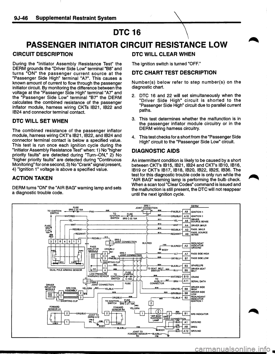
PASSENGER INITIATOR CIRCUIT RESISTANCE LOW
CIRCUIT DESCRIPTION
During the "Initiator Assembly Resistance Test" the
DERM grounds the "Driver
Side Low" terminal "B8" and
turns "ON" the passenger current source at the
"Passenger Side High" terminal "A7". This causes a
known amount of current to
flow through the passenger
initiator circuit. By monitoring the difference between the
voltage at the "Passenger Side High" terminal "A7" and
the "Passenger
Side Low" terminal "B7" the DERM
calculates the combined resistance of the passenger
inflator module, harness wiring CKTs IB21, IB22 and
IB24 and connector terminal contact.
DTC WILL SET WHEN
The combined resistance of the passenger inflator
module,
harness wiring CKT's IB21, IB22, and IB24 and
connector
terminal contact is below a specified value.
This test is run once each ignition cycle during the
"Initiator Assembly Resistance Test" when: 1) No "higher
priority
faults" are detected during "Turn-ON," 2) No
"higher priority
faults" are detected during "Continuous
Monitoring" for one second,
3) No "Crank" signal present,
4)
"Ignition 1" voltage is above a specified value.
ACTION TAKEN
DERM turns "ON" the "AIR BAG" warning lamp and sets
a diagnostic
trouble code.
1805
DTC WILL CLEAR WHEN
The ignition switch is turned "OFF."
DTC CHART TEST DESCRIPTION
Number(s) below refer to step number(s) on the
diagnostic chart.
2. DTC 16 and 22 will set simultaneously when the
"Driver Side High" circuit is shorted to the
"Passenger Side High" circuit due to parallel current
paths.
3. This test determines whether the malfunction is in
the passenger inflator module circuitry or in the
DERM wiring harness circuitry.
4. This test checks for a short from the "Passenger Side
High" circuit to the "Passenger Side Low" circuit.
DIAGNOSTIC AIDS
An intermittent condition is likely to be caused by a short
between CKT's
IB15, IB21, IB24 and CKT's IB10, IB16,
IB19
or CKT's IB17, IB18, IB20, IB22, IB25, IB36. The
test for this diagnostic
trouble code is only run while the
"AIR BAG" warning lamp is performing the bulb check.
When a scan
tool "Clear Codes" command is issued and
the
malfunction is still present, the DTC will not reappear
until the next ignition cycle.
SRS·1 JOINT CONNECTION 12 10 LBOe TO FUSE 1807 ~~~2~--SR~SC~-2+21-0A--~~--~---
IGNITION 1 IGNITION1 1111 1812 1813 DRIVER JeVLR
PASS. 36VLR
PASS. SOURCE
SENSE
REDUNDAT
INDICATOR
GROUND
PASS SIDE HIGH
PASS SIDE LOW
SERIAL DATA
SRS INDICATOR
•
Page 1680 of 1928
9J-56 Supplemental Restraint System
DTC22
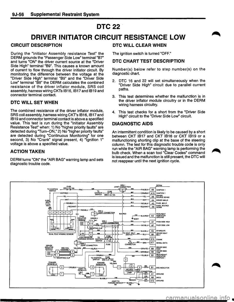
DRIVER INITIATOR CIRCUIT RESISTANCE LOW
CIRCUIT DESCRIPTION
During the "Initiator Assembly resistance Test" the
DERM grounds the "Passenger
Side Low" terminal "B7"
and turns "ON" the driver current source at the "Driver
Side High" terminal "B9". This causes a known amount
of current to flow through the driver initiator circuit. By
monitoring the difference between the voltage at the
"Driver Side High" terminal "B9" and the "Driver Side
Low"
terminal "B8" the DERM calculates the combined
resistance of the driver inflator module, SRS coil
assembly, harness wiring CKTs IB16, IB17 and IB19 and
connector terminal contact.
DTC WILL SET WHEN
The combined resistance of the driver inflator module,
SRS coil assembly, harness wiring CKT's IB16, IB17 and
IB19 and connector terminal contact is above a specified
value. This test is run during the
"Initiator Assembly
Resistance
Test" when: 1) No "higher priority faults" are
detected during
"Turn-ON," 2) No "higher priority faults"
are detected during "Continuous Monitoring" for one
second,
3) No "Crank" signal present, 4) "Ignition 1"
voltage is above a specified value.
ACTION TAKEN
DERM turns "ON" the "AIR BAG" warning lamp and sets
diagnostic trouble code.
DTC WILL CLEAR WHEN
The ignition switch is turned "OFF."
DTC CHART TEST DESCRIPTION
Number(s) below refer to step number(s) on the
diagnostic chart.
2. DTC 16 and 22 will set simultaneously when the
"Driver Side High" circuit due to parallel current
paths.
3. This test determines whether the malfunction is in
the driver inflator module circuitry or in the DERM
wiring harness circuitry.
4. This test checks for a short from the "Driver Side
High"
circuit to the "Driver Side Low'' circuit.
DIAGNOSTIC AIDS
An intermittent condition is likely to be caused by a short
between CKT
IB17 and CKT IB16 or CKT IB19 or a
malfunctioning shorting
clip at the base of the steering
column. The test for this diagnostic trouble code is only
run while the "AIR BAG" warning lamp is performing the
bulb check. When a scan tool
"Clear Codes" command
is issued and the malfunction is
still present, the DTC will
not reappear until the next ignition cycle.
SAS·1 JOINT CONNECTlON FUSE SASC-2310A -. IGNITION 1 IGJ,\\oN FUSE SWrrtH SRS C-22 10A
DRIVER 38VLR PASS.30VLA PASS. SOURCE SENSE
REDUNOAT INOtcATOR GROUND
PASS SIDE HIGH PASS SIDE LOW
SPAREAPS
SERIAL DATA
DRIVER SIDE HIGH DRIVER SIDE LOW REDUNDANT INDICATOR
IGNITION 1
SRS INDICATOR
..
Page 1700 of 1928
9J-76 Supplemental Restraint System
DTC34
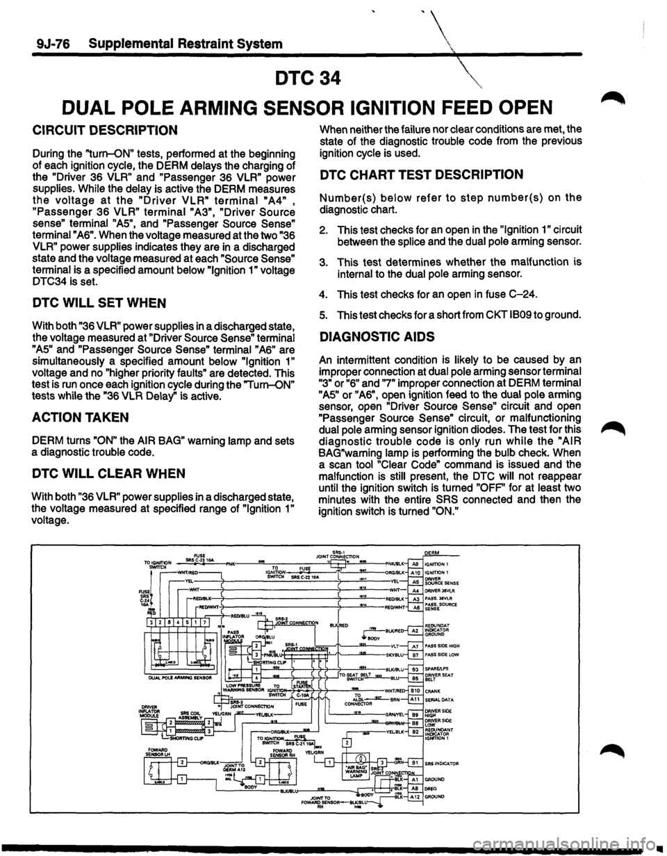
DUAL POLE ARMING SENSOR IGNITION FEED OPEN
CIRCUIT DESCRIPTION
During the "turn-ON" tests, performed at the beginning
of each ignition cycle, the DERM delays the charging of
the
"Driver 36 VLR" and "Passenger 36 VLR" power
supplies.
While the delay is active the DERM measures
the voltage at the "Driver VLR" terminal "A4" ,
"Passenger 36 VLR" terminal "A3", "Driver Source
sense" terminal "AS", and "Passenger Source Sense"
terminal "A6". When the voltage measured at the two "36
VLR" power supplies indicates they are in a discharged
state and the voltage measured at each
"Source Sense"
terminal is a specified amount below "Ignition 1" voltage
DTC34 is set.
DTC WILL SET WHEN
With both "36 VLR" power supplies in a discharged state,
the voltage measured at "Driver
Source Sense" terminal
"AS" and "Passenger Source Sense" terminal "A6" are
simultaneously a specified amount below
"Ignition 1"
voltage and no "higher priority faults" are detected. This
test is run once each ignition cycle during the "Turn-ON"
tests while the "36
VLR Delay" is active.
ACTION TAKEN
DERM turns "ON" the AIR BAG" warning lamp and sets
a diagnostic trouble code.
DTC WILL CLEAR WHEN
With both "36 VLR" power supplies in a discharged state,
the voltage measured at specified range of
"Ignition 1"
voltage. When
neither the failure nor clear conditions are met, the
state of the diagnostic trouble code from the previous
ignition cycle is used.
DTC CHART TEST DESCRIPTION
Number(s) below refer to step number(s) on the
diagnostic chart.
2. This test checks for an open in the "Ignition 1" circuit
between the
splice and the dual pole arming sensor.
3. This test determines whether the malfunction is
internal to the dual pole arming sensor.
4. This test checks for an open in fuse C-24.
s. This test checks for a short from CKT 1809 to ground.
DIAGNOSTIC AIDS
An intermittent condition is likely to be caused by an
improper connection at dual pole arming sensor terminal
"3" or "6" and "7" improper connection at DERM terminal
"AS" or "A6", open ignition feed to the dual pole arming
sensor, open "Driver
Source Sense" circuit and open
"Passenger
Source Sense" circuit, or malfunctioning
dual pole arming sensor ignition diodes. The test for this
diagnostic trouble code is only run while the "AIR
BAG"warning lamp is performing the bulb check. When
a scan tool "Clear Code" command is issued and the
malfunction
is still present, the DTC will not reappear
until the ignition switch is turned
"OFP' for at least two
minutes with the entire
SRS connected and then the
ignition switch is turned
"ON."
Ill
Page 1718 of 1928
9J-94 Supplemental Restraint System
DTC53
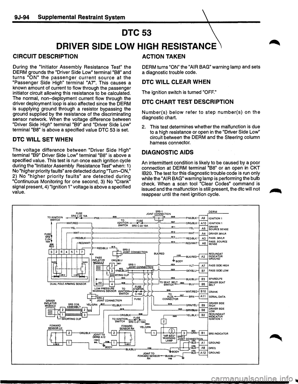
DRIVER SIDE LOW HIGH RESISTANCE
CIRCUIT DESCRIPTION
During the "Initiator Assembly Resistance Test" the
DERM grounds the "Driver Side
Low" terminal "B8" and
turns "ON" the passenger current source at the
"Passenger Side High" terminal "A7". This causes a
known amount of current to
flow through the passenger
initiator circuit
allowing this resistance to be calculated.
The normal, non-deployment current flow through the
driver
deployment loop is also affected since the DERM
is
supplying ground through a resistor bypassing the
ground
supplied by the resistance of the discriminating
sensor network. When the
voltage difference between
"Driver Side High" terminal "B9" and "Driver Side Low"
terminal "B8" is above a specified value DTC 53 is set.
DTC WILL SET WHEN
The voltage difference between "Driver Side High"
terminal "B9" Driver Side Low" terminal "B8" is above a
specified
value. This test
is run once each ignition
cycle
during the "Initiator Assembly Resistance Test" when: 1)
No "higher priority
faults" are detected during "Turn-O.N,"
2) No "higher priority faults" are detected dunng
"Continuous Monitoring for one second, 3) No "Crank"
signal
present, 4) "Ignition 1" voltage is above a specified
value.
ACTION TAKEN
DERM turns "ON" the "AIR BAG" warning lamp and sets
a diagnostic
trouble code.
DTC WILL CLEAR WHEN
The ignition switch is turned "OFF."
DTC CHART TEST DESCRIPTION
Number(s) below refer to step number(s) on the
diagnostic chart.
2. This test determines whether the malfunction is due
to a high resistance or open
in the "Driver Side Low"
circuit between the DERM and the Steering
column
harness connector.
DIAGNOSTIC AIDS
An intermittent condition is likely to be caused by a poor
connection at DERM
terminal "B8" or an open in CKT
IB20.
The test for this diagnostic trouble code is run only
while
the "AIR BAG" warning lamp is performing the bulb
check. When a scan tool "Clear Codes" command is
issued and the
malfunction is still present, the dtc will not
reappear
until the next ignition cycle.
iYOS BLK/RE
.rBODY t824 VLT IB21J
DRIVER 36VLR PASS. 38VLR PASS. SOURCE SENSE
PASS SIDE HIGH
PASS SIDE LOW
l---....!E:L_-+--4+j-+-___..!!IB3~4--BLK/BLU
~-'!W.-4---4-~----'TO ~iJELT '"*' BLU
SERIAL DATA
DRIVER SIDE HIGH DRIVER SIDE LOW REDUNDANT INDICATOR IGNITION 1
SRS INDICATOR
Page 1720 of 1928
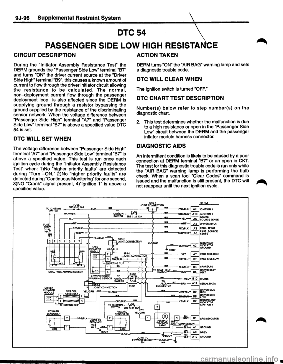
9J-96 Supplemental Restraint System
DTC54
PASSENGER SIDE LOW HIGH RESISTA E
CIRCUIT DESCRIPTION
During the "Initiator Assembly Resistance Test" the
DERM grounds the "Passenger Side Low"
terminal "B7''
and turns
"ON" the driver current source at the "Driver
Side High" terminal "B9". this causes a known amount of
current to
flow through the driver initiator circuit allowing
the resistance to be calculated. The normal,
non-deployment current flow through the passenger
deployment loop is also affected since the DERM is
supplying ground through a resistor bypassing the
ground
supplied by the resistance of the discriminating
sensor network. When the
voltage difference between
"Passenger Side
High" terminal "A7" and "Passenger
Side Low''
terminal "B7" is above a specified value DTC
54 is set.
DTC WILL SET WHEN
The voltage difference between "Passenger Side High"
terminal "A7"
and "Passenger Side Low" terminal "B7" is
above a specified
value. This test is run once each
ignition
cycle during the "Initiator Assembly Resistance
Test" when:
1 )No "higher priority faults" are detected
during
"Turn -ON," 2)No "higher priority faults" are
detected during
"Continuous Monitoring" for one second,
3)NO "Crank" signal present, 4)"1gnition 1" is above a
specified
value.
ACTION TAKEN
DERM turns "ON" the "AIR BAG" warning lamp and sets
a diagnostic
trouble code.
DTC WILL CLEAR WHEN
The ignition switch is turned "OFF."
DTC CHART TEST DESCRIPTION
Number(s) below refer to step number(s) on the
diagnostic chart.
2. This test determines whether the malfunction is due
to a high resistance or open in the "Passenger Side
Low" circuit between the DERM and the passenger
inflator module harness connector.
DIAGNOSTIC AIDS
An intermittent condition is likely to be caused by a poor
connection at DERM
terminal "B7" or an open in CKT.
The test for this diagnostic trouble code is run only while
the "AIR BAG" warning lamp is performing the bulb
check. When a scan tool "Clear Codes" command is
issued and the
malfunction is still present, the DTC will ~
not reappear until the next ignition cycle.
SRS-1 JOINT CONNECTION 1105 1 10 TO FUSE IGNITION SWITCH SRS C-22 10A
PASS SIDE HIGH
PASS SIDE LOW
SERIAL
DATA
SRS INDICA TOR
•
Page 1732 of 1928
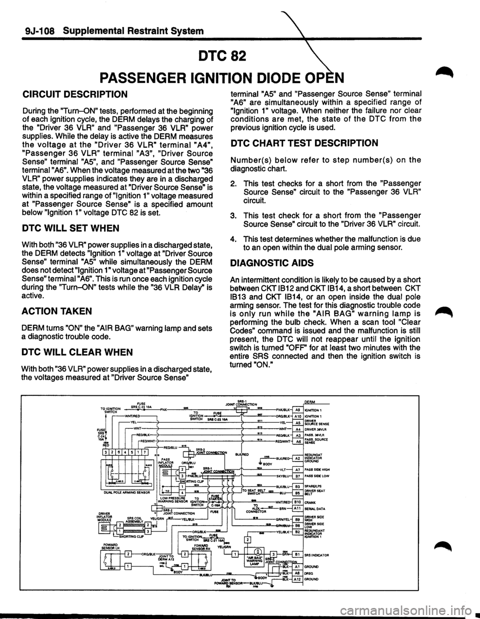
9J-1 08 Supplemental Restraint System
DTC82
PASSENGER IGNITION DIODE OP N
CIRCUIT DESCRIPTION
During the "Turn-ON" tests, performed at the beginning
of each ignition
cycle, the DERM delays the charging of
the "Driver 36
VLR" and "Passenger 36 VLR" power
supplies.
While the delay is active the DERM measures
the voltage at the "Driver 36 VLR" terminal "A4",
"Passenger 36 VLR" terminal "A3", "Driver Source
Sense"
terminal "AS", and "Passenger Source Sense"
terminal "A6". When the voltage measured at the two "36
VLR"
power supplies indicates they are in a discharged
state, the voltage measured at "Driver
Source Sense" is
within a specified range of
"Ignition 1" voltage measured
at "Passenger
Source Sense" is a specified amount
below "Ignition 1" voltage DTC 82 is set.
DTC WILL SET WHEN
With both "36 VLR" power supplies in a discharged state,
the DERM detects
"Ignition 1" voltage at "Driver Source
Sense" terminal
"AS" while simultaneously the DERM
does not detect
"Ignition 1" voltage at "Passenger Source
Sense"
terminal "A6". This is run once each ignition cycle
during the
"Turn-ON" tests while the "36 VLR Delay" is
active.
ACTION TAKEN
DERM turns "ON" the "AIR BAG" warning lamp and sets
a diagnostic trouble code.
DTC WILL CLEAR WHEN
With both "36 VLR" power supplies in a discharged state,
the voltages measured at "Driver
Source Sense"
'"'
terminal "AS" and "Passenger Source Sense" terminal
"A6" are simultaneously within a specified range of
"Ignition 1" voltage. When neither the failure nor clear
conditions are met, the state of the DTC from the
previous ignition cycle is used.
DTC CHART TEST DESCRIPTION
Number{s) below refer to step number{s) on the
diagnostic chart.
2. This test checks for a short from the "Passenger
Source Sense" circuit to the "Passenger 36 VLR"
circuit.
3. This test check for a short from the "Passenger
Source Sense" circuit to the "Driver 36 VLR" circuit.
4. This test determines whether the malfunction is due
to an open within the
dual pole arming sensor.
DIAGNOSTIC AIDS
An intermittent condition is likely to be caused by a short
between
CKT IB12 and CKT IB14, a short between CKT
IB13
and CKT IB14, or an open inside the dual pole
arming sensor. The test for this diagnostic trouble code
is only run while the "AIR BAG" warning lamp is
performing the bulb check. When a scan tool "Clear
Codes"
command is issued and the malfunction is still
present, the DTC will not reappear until the ignition
switch is turned
"OFP for at least two minutes with the
entire
SRS connected and then the ignition switch is
turned
"ON."
SRS-1 JOINT CONNEcnoN . lG,J;~ON _ _.::FU::OS£'---.-r:--m_-SWITCH SRS C..z2 10A
•