service ISUZU TROOPER 1995 Service Manual
[x] Cancel search | Manufacturer: ISUZU, Model Year: 1995, Model line: TROOPER, Model: ISUZU TROOPER 1995Pages: 1928
Page 211 of 1928
SUPPLEMENTAL RESTRAINT SYSTEM (SRSl STEERING WHEEL & COLUMN 3F4-1
SECTION 3F4
SUPPLEMENTAL RESTRAINT SYSTEM
STEERING
WHEEL & COLUMN
W CAUTION:
When fasteners are removed, always reinstall them at the same location from which they were removed.
If a fastener needs to be replaced, use the correct part number fastener for that application. If the correct
part
number fastener is not available, a fastener of equal size and strength (or stronger) may be used.
Fasteners
that are not reused, and those requiring thread locking compound, will be called out. The correct
torque value must be used when installing fasteners that require it. If the above conditions are not
followed, parts or system damage could result.
CONTENTS
General Description .......................................... 3F4-1
Lock Cylinder Replacement ......................... 3F4-10
On-Vehicle Service
............................................ 3F4-2 Steering Column Replacement .................... 3F4-13
Special Service Precaution ........................... 3F4-2 Main Data and Specifications .......................... 3F4-17
Inflator Module Replacement ...................... 3F4-3 Torque
Specifications ................................... 3F4-17
Steering Wheel Replacement ...................... 3F4-4 Special Tools ..................................................... 3F4-17
Combination
Switch Replacement ............. 3F4-7
GENERAL DESCRIPTION
W WARNING
TO AVOID DEPLOYMENT WHEN TROUBLE
SHOOTING
THE SRS SYSTEM, DO NOT USE
ELECTRICAL TEST EQUIPMENT, SUCH AS
BATTERY-POWERED OR A/C-POWERED VOLT
METER, OHMMETER, ETC., OR ANY TYPE OF
ELECTRICAL EQUIPMENT OTHER THAN SPE
CIFIED IN THIS MANUAL. DO NOT USE A NON
POWERED
PROBE-TYPE TESTER.
INSTRUCTION IN THIS MANUAL MUST BE
FOLLOWED CAREFULLY, OTHERWISE PER
SONAL INJURY MAY RESULT.
This steering
wheel and column repair section covers
the Supplemental Restraint System (SRS) steering
column. The following repair procedures are specific
to SRS Components. When servicing a vehicle
equipped with Supplemental Restraint System, pay
close attention to all WARNINGS and CAUTIONS.
For detailed explanation about SRS, refer to Section
9J "SUPPLEMENTAL
RESTRAINT SYSTEM (SRS)" of
this manual.
The steering column has three important features in
addition to the steering function:
1. The column is energy absorbing, designed to
compress in a front-end collision to minimize the
possibility of injury to the driver of the vehicle.
2. The ignition switch and lock are mounted con
veniently on the column.
3. With the column mounted lock, the ignition and
steering operation can be
locked to prevent theft
of the vehicle.
The column may be disassembled and reassembled.
To insure the energy absorbing action, it is important
that the specified screws, bolts and nuts be used only
as designated and that they are tightened to the
specified torque.
When the column is removed from the vehicle, a
sharp
blow on the end of steering shaft or shift lever,
leaning
on the column assembly, or dropping the
assembly could shear or loosen the fasteners that
maintain column rigidity.
Page 212 of 1928
3F4-2 SUPPLEMENTAL RESTRAINT SYSTEM (SRSI STEERING WHEEL & COLUMN
ON-VEHICLE SERVICE
SPECIAL SERVICE PRECAUTIONS
\f CAUTION:
Safe
handling of Inflator modules requires fol
lowing the procedures described below for both
live and deployed modules.
\f WARNING
SAFETY PRECAUTIONS MUST BE FOLLOWED
WHEN HANDLING A DEPLOYED INFLATOR
MODULE (AIR
BAG). AFTER DEPLOYMENT, THE
INFLATOR MODULE (AIR BAG) SURFACE MAY
CONTAIN A SMALL AMOUNT OF SODIUM
HYDROXIDE,
A BY-PRODUCT OF THE DEPLOY
MENT REACTION, THAT IS IRRITATING TO THE
SKIN AND EYES. MOST OF THE POWDER ON
THE INFLATOR MODULE (AIR BAG) IS HARM
LESS. AS A PRECAUTION, WEAR GLOVES AND
SAFETY GLASSES WHEN HANDLING A DE
PLOYED INFLATOR MODULE (AIR BAG), AND
WASH YOUR HANDS WITH MILD SOAP AND
WATER AFTERWARDS.
WHEN CARRYING A
LIVE INFLATOR MODULE
(AIR
BAG), MAKE SURE THE BAG AND TRIM
COVER ARE POINTED AWAY FROM YOU.
NEVER CARRY AN INFLATOR MODULE (AIR
BAG) BY THE WIRES OR CONNECTOR ON THE
UNDERSIDE OF MODULE. IN THE CASE OF AN
ACCIDENTAL DEPLOYMENT,
THE BAG WILL
THEN DEPLOY WITH MINIMAL CHANCE OF
INJURY. WHEN PLACING A LIVE INFLATOR
MODULE (AIR
BAG) ON A BENCH OR OTHER
SURFACE, ALWAYS FACE THE BAG AND TRIM
COVER UP, AWAY FROM THE SURFACE.
NEVER
REST A STEERING COLUMN AS
SEMBLY ON
THE STEERING WHEEL WITH THE
INFLATOR MODULE (AIR BAG) FACE DOWN
AND COLUMN VERTICAL. THIS IS NECESSARY
SO THAT A FREE SPACE IS PROVIDED TO AL
LOWTHE INFLATOR MODULE (AIR BAG) TO EX
PAND
IN THE UNLIKELY EVENT OF ACCI
DENTAL DEPLOYMENT.
OTHERWISE, PERSO
NAL INJURY COULD RESULT.
For detailed explanation
about SRS, refer to Section
9J "SUPPLEMENTAL
RESTRAINT SYSTEM (SRS)" of
this manual.
SRS CONNECTORS
w CAUTION:
Double-lock type yellow color connectors are
used
for supplemental restraint system-air bag
circuit.
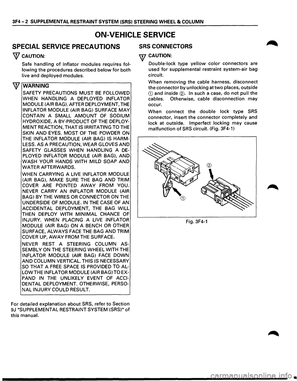
When removing the cable harness, disconnect
the connector by unlocking at two places, outside
CD and inside®. In such a case, do not pull the
cables. Otherwise, cable disconnection may
occur.
When connect the double lock type SRS
connector, insert the connector completely and
lock at outside. Imperfect locking
may cause
malfunction of SRS circuit. (Fig. 3F4-1)
®
Fig. 3F4-1
•
Page 229 of 1928
PROPELLER SHAFT 4A-1
SECTION 4A
PROPELLER SHAFT AND AXLE
CONTENTS
Propeller Shaft . . . . . . . . . . . . . . . . . . . . . . . . . . . . . . . . . . . . . . . . . . . . . . . . . . . . . . . . . . . . . . . . . . Section 4A
Rear Axle . . . . . . . . . . . . . . . . . . . . . . . . . . . . . . . . . . . . . . . . . . . . . . . . . . . . . . . . . . . . . . . . . . . . . . . Section 48
Front Driving Axle . . . . . . • . . . . . . . . . . . . . . . . . . . . . . . . . . . . . . . . . . . . . . . . . . . . . . . . . . . . . . . . Section 4C
SECTION 4A
PROPELLER SHAFT
\fl CAUTION:
VI When fasteners are removed, always reinstall them at the same location from which they were removed. If a
fastener needs
to be replaced, use the correct part number fastener for that application. If the correct part
number fastener is
not available, a fastener of equal size and strength (or stronger) may be used. Fasteners
that are
not reused, and those requiring thread locking compound, will be called out. The correct torque
values must be used when installing fasteners that require torque. If the above conditions are not followed, •
parts or system damage could result.
CONTENTS
General Description . . . . . . . . . . . . . . . . . . . . . 4A-1
On-Vehicle Service . . . . . . . . . . . . . . . . . . . . . 4A-2
Rear
Propeller Shaft . . . . . . . . . . . . . . . . . . 4A-2
Front Propeller Shaft . . . . . . . . . . . . . . . . . . 4A-3
Unit Repair ............................ 4A-4
Rear
Propeller Shaft . . . . . . . . . . . . . . . . . . 4A-4
Universal Joint (Rear Propeller Shaft) .... 4A-5
Front Propeller Shaft .................. 4A-8
Universal Joint (Front Propeller Shaft) ... 4A-9
Main Data and Specifications ............ 4A-12
General Specifications ................ 4A-12
Torque Specifications ................ 4A-13
GENERAL DESCRIPTION
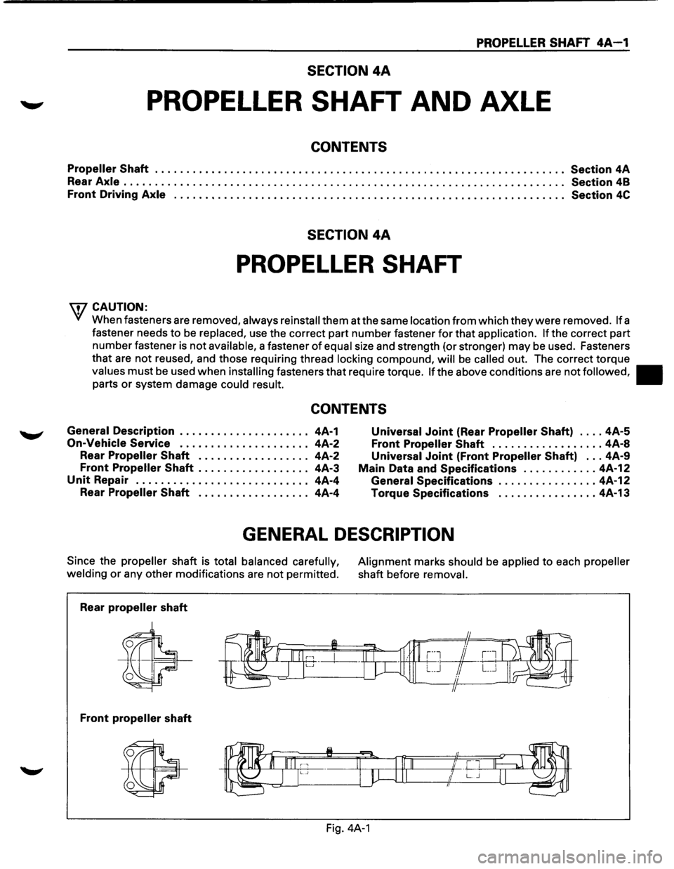
Since the propeller shaft is total balanced carefully,
welding
or any other modifications are not permitted.
Rear
propeller shaft
Front propeller shaft
Alignment marks should be applied to each propeller
shaft before removal.
Fig. 4A-1
Page 230 of 1928
4A-2 PROPELLER SHAFT
ON-VEHICLE SERVICE
Preparation:
• Jack up the vehicle and support it on the chassis •
stands. Gear
shift
lever should be placed in neutral
position and parking brake released.
REAR PROPELLER SHAFT
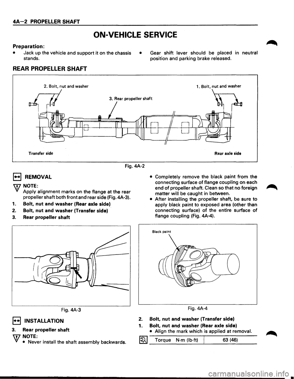
1. Bolt, nut and washer
3. Rear propeller shaft
~
Transfer side
Rear axle side
Fig. 4A-2
B REMOVAL
\fl NOTE:
VI Apply alignment marks on the flange at the rear
propeller shaft both front and rear side (Fig. 4A-3).
1. Bolt, nut and washer (Rear axle side)
2. Bolt, nut and washer (Transfer side)
3. Rear propeller shaft
Fig. 4A-3
1••1 INSTALLATION
3. Rear propeller shaft
\flNOTE:
VI • Never install the shaft assembly backwards.
• Completely remove the black paint from the
connecting surface
of flange coupling on each
end
of propeller shaft. Clean so that no foreign ~
matter will be caught in between.
• After installing the propeller shaft, be sure to
apply black paint to exposed area (other than
connecting surface)
of the entire surface of
flange coupling (Fig. 4A-4).
Fig. 4A-4
2. Bolt, nut and washer (Transfer side)
1.
Bolt, nut and washer (Rear axle side)
• Align the mark which is applied at removal.
~~~ Torque N·m (lb·ft) I 63 (46)
•
Page 243 of 1928
REAR AXLE 48-1
SECTION 48
REAR AXLE
\V CAUTION:
When fasteners are removed, always reinstall them at the same location from which they were removed.
If a fastener needs to be replaced, use the correct part number fastener for that application. If the correct
part number fastener is not available, a fastener of equal size and strength (or stronger) may be used.
Fasteners
that are not reused, and those requiring thread locking compound, will be called out. The
correct
torque values must be used when installing fasteners that require torque. If the above conditions
are not followed, parts or system damage could result.
CONTENTS
General Description . . . . . . . . . . . . . . . . . . . . 48-1
Diagnosis of Rear
Axle Noise . .
. . . . . . . . . . 48-3
On-Vehicle Service ..................... 48-4
Axle Housing . .
. . . . . . . . . . . . . . . . . . . . . 48-4
Axle Shaft . .
. . . . . . . . . . . . . . . . . . . . . . . . 48-7
Pinion
Oil Seal . .
. . . . . . . . . . . . . . . . . . . .
48-10
Differential Assembly
. .
. . . . . . . . . . . . . . 48-11 Unit
Repair . . . . . . . . . . . . . . . . . . . . . . . . . . . 48-13
Differential Assembly . .
. . . . . . . . . . . . . .
48-13 Differential Cage Assembly . . . . . . . . . . . . 48-23
Limited
Slip Differential . .
. . . . . . . . . . . . 48-27
Main Data and Specifications . . . . . . . . . . . . 48-33
General Specifications . .
. . . . . . . . . . . . . . 48-33
Torque Specifications
................ 48-34
Special Tools ......................... 48-35
GENERAL DESCRIPTION
The rear axle assembly is of the semi-floating type in
which the vehicle weight is carried on the axle
housing (Fig. 48-1).
The center
line of the pinion gear is below the center
line of the ring gear (hypoid drive).
All parts necessary to transmit power from the
propeller shaft to the rear wheels are enclosed in a
banjo type axle housing.
The 8.7 inch ring gear rear axle uses a conventional
ring and
pinion gear set to transmit the driving force
of the engine to the rear wheels. This gear set transfers
this driving force at a 90 degree angle from the
propeller shaft to the drive shafts. The
axle shafts
are supported at the wheel end of the
shaft by a roller bearing.
The
pinion gear is supported by two tapered roller
bearings. The pinion depth is set by a shim pack
located between the gear end of the pinion and the
roller bearing that is pressed onto the pinion. The
pinion bearing preload is set by crushing a collapsible
spacer between the bearings in the axle housing.
Page 246 of 1928
48-4 REAR AXLE
ON-VEHICLE SERVICE
AXLE HOUSING
; ~~:r~4 ,
L ___________ j
12 14
3a
1
• 3
~
~·
13 5
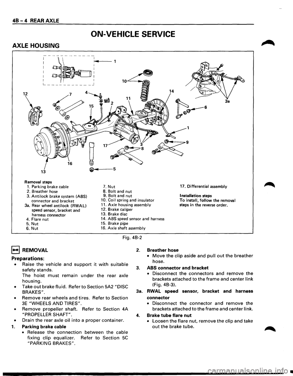
Removal steps
1. Parking brake cable 7. Nut 17.
Differential assembly
2. Breather hose 8.
Bolt and nut 9. Bolt and nut Installation steps
3. Anti lock brake system (ABS)
connector and bracket 10. Coil spring and insulator To install, follow the removal
steps in the reverse order.
3a. Rear wheel antilock (RWAL)
speed sensor, bracket and
harness connector 11.
Axle housing assembly
12. Brake caliper
13. Brake disc
4. Flare
nut 14. ABS speed sensor and harness
5. Nut 15.
Brake pipe
6. Nut 16.
Axle shaft assembly
Fig. 4B-2
1••1 REMOVAL
Preparations:
• Raise the vehicle and support it with suitable
safety stands.
The
hoist must remain under the rear axle
housing.
• Take out brake fluid. Refer to Section 5A2 "DISC
BRAKES".
•
Remove rear wheels and tires. Refer to Section
3E "WHEELS AND TIRES".
•
Remove propeller shaft. Refer to Section 4A
"PROPELLER SHAFT".
•
Drain the rear axle oil into a proper container.
1. Parking brake cable
•
Release the connection between the cable
fixing clip equalizer. Refer to Section 5C
"PARKING BRAKES".
2. Breather hose
• Move the clip aside and pull out the breather
hose.
3. ABS connector and bracket
• Disconnect the connectors and remove the
brackets attached to the frame and center link
(Fig. 4B-3).
3a. RWAL speed sensor,
bracket and harness
connector
• Disconnect the connector and remove the
brackets attached to the frame and center link.
4. Brake tube flare nut
• Loosen the flare nut, remove the clip and take
out the brake tube.
•
Page 279 of 1928
FRONT DRIVING AXLE 4C-1
SECTION 4C
FRONT DRIVING AXLE
'f CAUTION:
When fasteners are removed, always reinstall them at the same location from which they were removed.
If a fastener needs to be replaced, use the correct part number fastener for that application. If the correct
part
number fastener is not available, a fastener of equal size and strength (or stronger) may be used.
Fasteners
that are not reused, and those requiring thread locking compound, will be called out. The
correct
torque values must be used when installing fasteners that require torque. If the above conditions
are not followed, parts or system damage could result.
CONTENTS
General Description . . . . . . . . . . . . . . . . . . . . 4C-1
Diagnosis
of Front Driving Axle . . . . . . . . . . . 4C-2
Automatic Locking Free Wheel Hub . . . . . 4C-3
On-Vehicle Service ..................... 4C- 4
Pinion
Shaft Oil Seal Replacement . . . . . . 4C-4
Front Drive Shaft Joints Replacement . . . 4C-5
Front Hub Bearing Preload Check . . . . . . . 4C-5
Unit Repair . . . . . . . . . . . . . . . . . . . . . . . . . . . . 4C-6
Front Drive Axle Assembly . . . . . . . . . . . . 4C-6
Front Axle Drive Shaft . . . . . . . . . . . . . . . . 4C-9
Differential Assembly ................. 4C-14
Differential Cage Assembly . . . . . . . . . . . . 4C-24
Front Hub and Disc (4WD Model with
Automatic Locking Hub) . . . . . . . . . . . . 4C-28
Main Data and Specifications . . . . . . . . . . . . 4C-37
General Specifications . .
. . . . . . . . . . . . . . 4C-37
Torque Specifications ................. 4C-38
Special Tools .......................... 4C-41
GENERAL DESCRIPTION
This publication contains essential removal, instal
lation,
adjustment and maintenance procedures.
The
front axle utilizes a central disconnect type front
axle/transfer case system. The
drive axles are completely flexible assemblies,
consisting
of inner and outer constant velocity (CV)
drive shaft joints connected by an axle shaft. For
description
of front propeller shaft and universal
joint, refer to Section 4A "PROPELLER SHAFT".
Page 282 of 1928
4C-4 FRONT DRIVING AXLE
ON-VEHICLE SERVICE
PINION SHAFT OIL SEAL REPLACEMENT
1
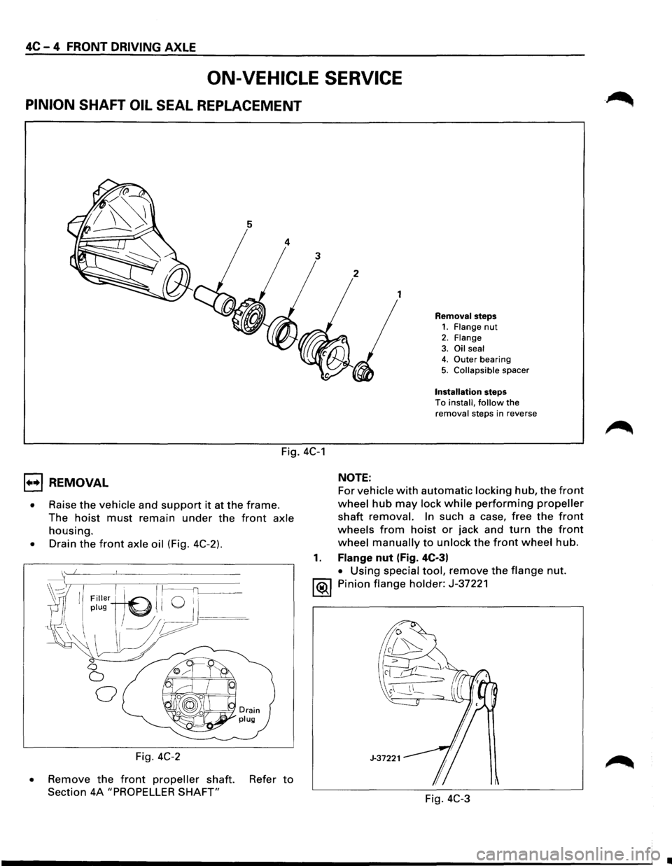
Removal steps 1. Flange nut
2. Flange 3. Oil seal 4. Outer bearing
5. Collapsible spacer
Installation steps To install, follow the removal steps in reverse
Fig. 4C-1
1••1 REMOVAL
• Raise the vehicle and support it at the frame.
The
hoist must remain under the front axle
housing.
• Drain the front axle oil (Fig. 4C-2).
~wIll ~I · I ~----fl______~~-' Filler (./ Q i,
//plug ~ I ) . ---
-\\I 11/~/~
~ <:1 0
0
0
Fig. 4C-2
•
Remove the front propeller shaft. Refer to
Section 4A "PROPELLER SHAFT"
NOTE:
For vehicle with automatic locking hub, the front
wheel hub may lock while performing propeller
shaft removal. In such a case, free the front
wheels from hoist or jack and turn the front
wheel manually to unlock the front wheel hub.
1. Flange nut (Fig. 4C-3)
• Using special tool, remove the flange nut.
1®.1 Pinion flange holder: J-37221
Fig.
4C-3
•
Page 321 of 1928
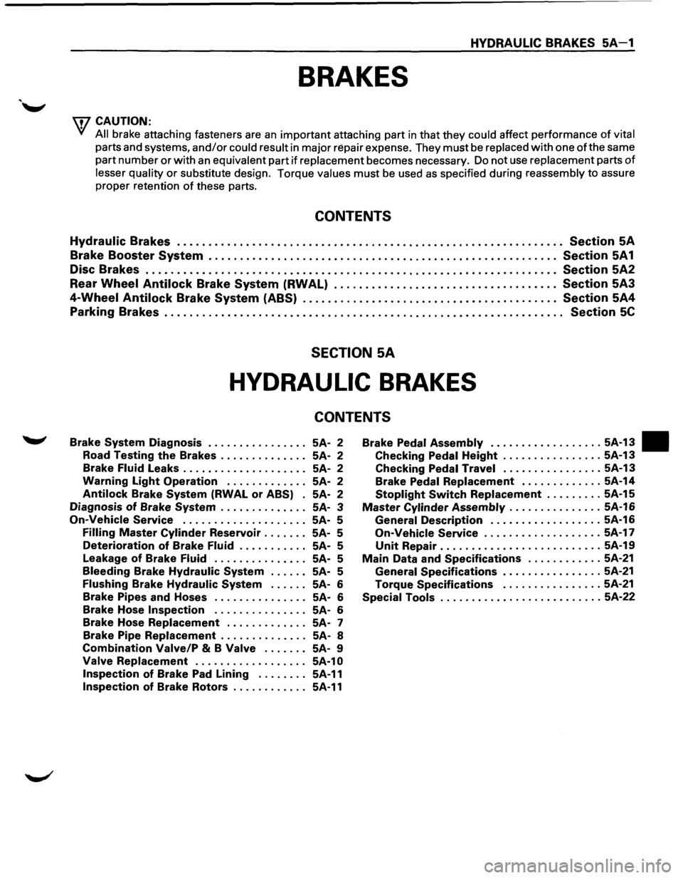
HYDRAULIC BRAKES SA-1
BRAKES
w CAUTION:
• All
brake attaching fasteners are an important attaching part in that they could affect performance of vital
parts and systems, and/or could result in major repair expense. They must be replaced with one of the same
part
number or with an equivalent part if replacement becomes necessary. Do not use replacement parts of
lesser quality or substitute design. Torque values must be used as specified during reassembly to assure
proper retention
of these parts.
CONTENTS
Hydraulic Brakes . . . . . . . . . . . . . . . . . . . . . . . . . . . . . . . . . . . . . . . . . . . . . . . . . . . . . . . . . . . . . . Section SA
Brake Booster System ........................................................ Section 5A1
Disc Brakes . . . . . . . . . . . . . . . . . . . . . . . . . . . . . . . . . . . . . . . . . . . . . . . . . . . . . . . . . . . . . . . . . . Section 5A2
Rear
Wheel Antilock Brake System (RWAL) .................................... Section 5A3
4-Wheel Antilock Brake System (ABS) ......................................... Section 5A4
Parking Brakes . . . . . . . . . . . . . . . . . . . . . . . . . . . . . . . . . . . . . . . . . . . . . . . . . . . . . . . . . . . . . . . .
Section 5C
SECTION 5A
HYDRAULIC BRAKES
CONTENTS
Brake System Diagnosis ................ SA-2
Road
Testing the Brakes . . . . . . . . . . . . . . SA-2
Brake
Fluid Leaks . . . . . . . . . . . . . . . . . . . . SA-2
Warning Light Operation . . . . . . . . . . . . . SA-2
Antilock Brake System (RWAL or ABS) . SA- 2
Diagnosis of Brake System . . . . . . . . . . . . . . SA-3
On-Vehicle Service .................... SA- S
Filling Master Cylinder Reservoir . . . . . . . SA-S
Deterioration of Brake Fluid . . . . . . . . . . . SA-S
Leakage
of Brake Fluid . . . . . . . . . . . . . . . SA-S
Bleeding Brake Hydraulic System . . . . . . SA-S
Flushing Brake Hydraulic System . . . . . . SA-6
Brake Pipes
and Hoses . . . . . . . . . . . . . . . SA-6
Brake Hose
Inspection . . . . . . . . . . . . . . . SA-6
Brake Hose
Replacement . . . . . . . . . . . . . SA-7
Brake Pipe
Replacement . . . . . . . . . . . . . . SA-8
Combination Valve/P & B Valve . . . . . . . SA-9
Valve Replacement . . . . . . . . . . . . . . . . . . SA-1 0
Inspection of Brake Pad Lining . . . . . . . . SA-11
Inspection of Brake Rotors . . . . . . . . . . . . SA-11
Brake Pedal Assembly .................. SA-13 •
Checking Pedal Height ................ SA-13
Checking Pedal Travel ................ SA-13
Brake
Pedal Replacement ............. SA-14
Stoplight Switch Replacement ......... SA-1S
Master Cylinder Assembly ............... SA-16
General Description .................. SA-16
On-Vehicle Service ................... SA-17
Unit Repair .......................... SA-19
Main Data and Specifications ............ SA-21
General Specifications ................ SA-21
Torque Specifications ................ SA-21
Special Tools .......................... SA-22
Page 325 of 1928
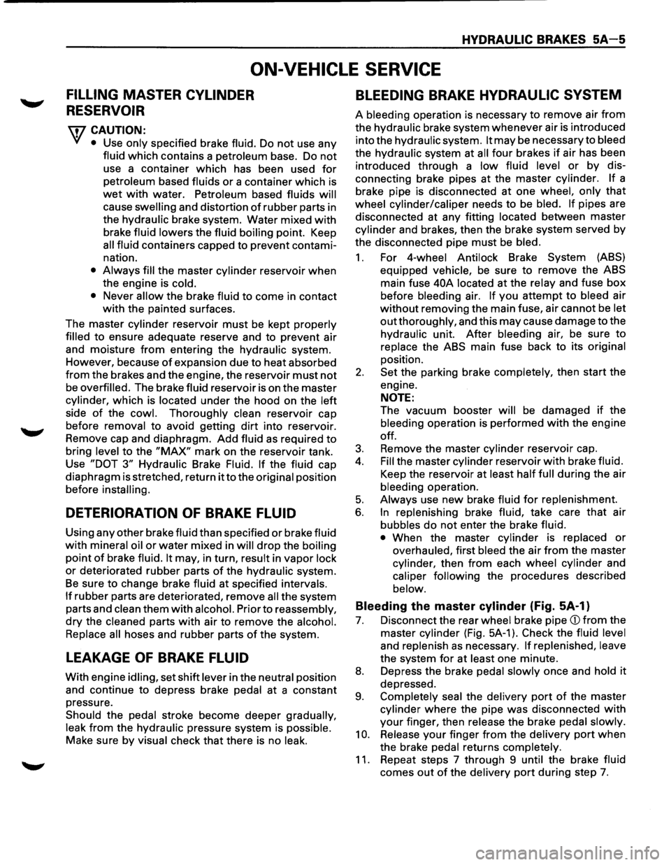
HYDRAULIC BRAKES 5A-5
ON-VEHICLE SERVICE
FILLING MASTER CYLINDER
RESERVOIR
'\fl CAUTION:
'VI • Use only specified brake fluid. Do not use any
fluid which contains a petroleum base. Do not
use a container which has been used for
petroleum based fluids or a container which is
wet with water. Petroleum based fluids will
cause swelling and distortion of rubber parts in
the
hydraulic brake system. Water mixed with
brake fluid lowers the fluid boiling point. Keep
all fluid containers capped to prevent contami
nation.
• Always fill the master cylinder reservoir when
the engine is
cold.
•
Never allow the brake fluid to come in contact
with the painted surfaces.
The master
cylinder reservoir must be kept properly
filled
to ensure adequate reserve and to prevent air
and moisture
from entering the hydraulic system.
However, because
of expansion due to heat absorbed
from the brakes and the engine, the reservoir must not
be overfilled. The brake fluid reservoir is on the master
cylinder, which is located under the hood on the
left
side of the cowl. Thoroughly clean reservoir cap
before
removal to avoid getting dirt into reservoir.
Remove cap and diaphragm.
Add fluid as required to
bring level to the "MAX" mark on the reservoir tank.
Use
"DOT 3" Hydraulic Brake Fluid. If the fluid cap
diaphragm is stretched, return
it to the original position
before
installing.
DETERIORATION OF BRAKE FLUID
Using any other brake fluid than specified or brake fluid
with mineral oil or water mixed in will drop the boiling
point of brake fluid. It may, in turn, result in vapor lock
or deteriorated rubber parts of the hydraulic system.
Be sure to change brake fluid at specified intervals.
If rubber parts are deteriorated, remove all the system
parts and
clean them with alcohol. Prior to reassembly,
dry the cleaned parts with air to remove the alcohol.
Replace all
hoses and rubber parts of the system.
LEAKAGE OF BRAKE FLUID
With engine idling, set shift lever in the neutral position
and continue to depress brake
pedal at a constant
pressure.
Should the pedal stroke become deeper gradually,
leak from the hydraulic pressure system is possible.
Make sure
by visual check that there is no leak.
BLEEDING BRAKE HYDRAULIC SYSTEM
A bleeding operation is necessary to remove air from
the hydraulic brake system whenever air is introduced
into the hydraulic system.
It may be necessary to bleed
the hydraulic system at all four brakes if air has been
introduced through a
low fluid level or by dis
connecting brake pipes at the master cylinder. If a
brake pipe is disconnected at one
wheel, only that
wheel cylinder/caliper needs to be bled. If pipes are
disconnected at any fitting
located between master
cylinder and brakes, then the brake system served by
the disconnected pipe must
be bled.
1. For 4-wheel Antilock Brake System (ABS)
equipped
vehicle, be sure to remove the ABS
main fuse
40A located at the relay and fuse box
before
bleeding air. If you attempt to bleed air
without removing the main fuse, air cannot be let
out thoroughly, and this may cause damage to the
hydraulic unit.
After bleeding air, be sure to
replace the ABS main fuse back to its original
position.
2. Set the parking brake completely, then start the
engine.
NOTE:
The vacuum booster will be damaged if the
bleeding operation is performed with the engine
off.
3. Remove the master cylinder reservoir cap.
4. Fill the master cylinder reservoir with brake fluid.
Keep the reservoir at least half full during the air
bleeding operation.
5. Always use new brake fluid for replenishment.
6. In replenishing brake fluid, take care that air
bubbles do not enter the brake fluid.
•
When the master cylinder is replaced or
overhauled, first bleed the air from the master
cylinder, then from each
wheel cylinder and
caliper following the procedures described
below.
Bleeding the master cylinder (Fig. 5A-1}
7. Disconnect the rear wheel brake pipe
cylinder (Fig. 5A-1 ). Check the fluid level
and replenish as necessary. If replenished, leave
the system for at least one minute.
8. Depress the brake pedal slowly once and hold it
depressed.
9. Completely seal the delivery port of the master
cylinder where the pipe was disconnected with
your finger, then release the brake pedal slowly.
10. Release your finger from the delivery port when
the brake
pedal returns completely.
11. Repeat steps 7 through 9 until the brake fluid
comes out of the delivery port during step 7.