service ISUZU TROOPER 1995 Manual PDF
[x] Cancel search | Manufacturer: ISUZU, Model Year: 1995, Model line: TROOPER, Model: ISUZU TROOPER 1995Pages: 1928
Page 524 of 1928
&A-8 GENERAL ENGINE MECHANICAL
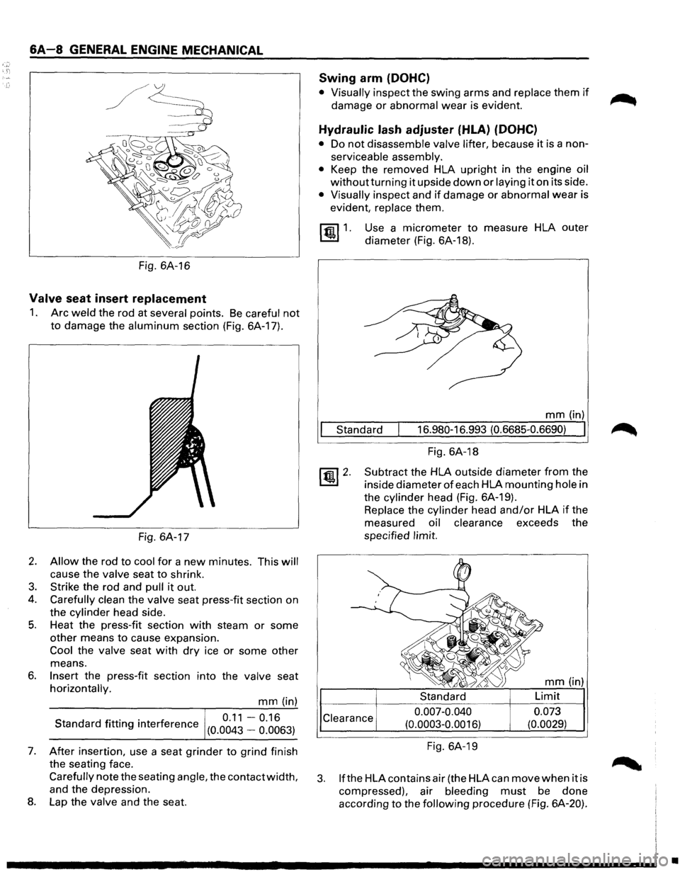
Fig. 6A-16
Valve seat insert replacement
1. Arc weld the rod at several points. Be careful not
to damage the aluminum section (Fig. 6A-17).
Fig. 6A-17
2. Allow the rod to cool for a new minutes. This will
cause the valve seat to shrink.
3. Strike the rod and pull it out.
4. Carefully clean the valve seat press-fit section on
the
cylinder head side.
5. Heat the press-fit section with steam or some
other means
to cause expansion.
Cool the valve seat with dry ice or some other
means.
6. Insert the press-fit section into the valve seat
horizontally.
mm (in)
S d df. 0 0 f 0.11-0.16 tan ar 1tt1ng 1nter erence (0.0043 _ 0_
0063 )
7. After insertion,
use a seat grinder to grind finish
the seating face.
Carefully note the seating angle, the contact width,
and the depression.
8. Lap the valve and the seat.
Swing arm (DOHC)
• Visually inspect the swing arms and replace them if
damage or abnormal wear is evident.
Hydraulic lash adjuster (HLA) (DOHC}
• Do not disassemble valve lifter, because it is a non
serviceable assembly.
•
Keep the removed HLA upright in the engine oil
withoutturning it upside down or laying it on its side.
• Visually inspect and if damage or abnormal wear is
evident,
replace them.
[§) 1. Use a micrometer to measure HLA outer
diameter (Fig. 6A-18).
mm (in)
Standard 16.980-16.993
(0.6685-0.6690) I
Fig.
6A-18
Subtract the HLA outside diameter
from the
inside diameter
of each HLA mounting hole in
the
cylinder head (Fig. 6A-19).
Replace the cylinder head and/or HLA if the
measured
oil clearance exceeds the
specified
limit.
Clearance 0.007-0.040
(0.0003-0.0016)
Fig. 6A-19
mm (in)
0.073
(0.0029)
3. lfthe HLA contains air (the HLA can move when it is
compressed). air
bleeding must be done
according
to the following procedure (Fig. 6A-20).
•
Page 546 of 1928
6A-30 GENERAL ENGINE MECHANICAL
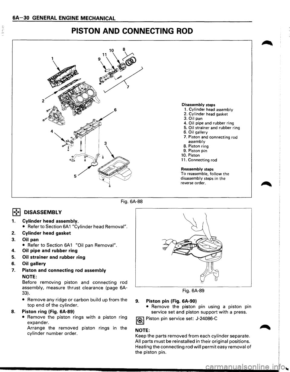
PISTON AND CONNECTING ROD
1
~~ $ 7
2 6 Disassembly
steps
1. Cylinder head assembly 2. Cylinder head gasket 3. Oil pan
4. Oil pipe and rubber ring
5. Oil strainer and rubber ring
6. Oil gallery
7. Piston and connecting rod assembly 8. Piston ring
9. Piston pin
10. Piston
11. Connecting rod
Reassembly steps
To reassemble, follow the disassembly steps in the reverse order.
Fig. 6A-88
1•! .. 1 DISASSEMBLY
1. Cylinder head assembly.
• Refer to Section 6A 1 "Cylinder head Removal".
2. Cylinder head gasket
3. Oil pan
• Refer to Section 6A1 "Oil pan Removal".
4. Oil pipe and rubber ring
5. Oil strainer and rubber ring
6. Oil gallery
7. Piston and connecting rod assembly
NOTE:
Before removing piston and connecting rod
assembly, measure thrust clearance (page 6A-
33).
• Remove any ridge or carbon build up from the
top end of the cylinder.
8. Piston ring (Fig. 6A-89)
• Remove the piston rings with a piston ring
expander.
Arrange the removed piston rings in the
cylinder number order. Fig.
6A-89
9. Piston pin (Fig. 6A-90)
• Remove the piston pin using a piston pin
service set and piston
support with a press.
1®1 Piston pin service set: J-24086-C
NOTE: Keep the parts removed
from each cylinder separate.
All parts must be reinstalled in their original positions.
Heating the connecting rod
will permit easy removal of
the piston pin.
Page 551 of 1928
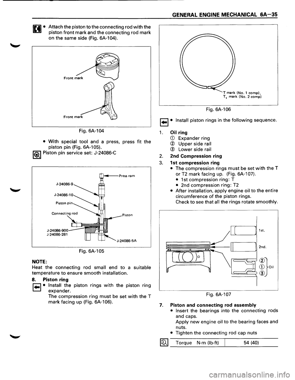
Attach the piston to the connecting rod with the
piston
front mark and the connecting rod mark
on the same side (Fig. 6A-104).
Fig. 6A-104
• With special tool and a press, press fit the
piston pin (Fig. 6A-105).
1®1 Piston pin service set: J-24086-C
NOTE:
J-24086-900 J-24086-281
Fig. 6A-105
J-24086-5A
Heat the connecting rod small end to a suitable
temperature to ensure smooth installation.
8. Piston ring
r=1 • Install the piston rings with the piston ring
1=.1 expander.
The compression ring
must be set with the T
mark facing up (Fig. 6A-106).
GENERAL ENGINE MECHANICAL &A-35
T mark (No.1 comp), T2 mark (No.2 comp)
Fig. 6A-106
1 ... 1• Install piston rings in the following sequence.
1. Oil ring
CD Expander ring
® Upper side rail
® Lower side rail
2. 2nd Compression ring
3. 1st compression ring
• The compression rings must be set with the T
or
T2 mark facing up. (Fig. 6A-1 07).
•
1st compression ring: T
• 2nd compression ring: T2
• After installation, apply engine oil to the entire
circumference
of the piston rings.
Check to see that all the rings rotate smoothly.
Fig. 6A-107
7. Piston and connecting rod assembly
• Insert
the bearings into the connecting rods
and caps.
Apply new engine oil to the bearing faces and
nuts.
• Tighten the connecting rod cap nuts
1~1 Torque N·m (lb·ft) 54 (40)
Page 559 of 1928
ENGINE (V6 3.2L DOHC AND SOHC) 6A 1-1
SECTION 6A1
3.2L V6 ENGINE
CONTENTS
General Description .................. 6A1-2 Crankshaft Pulley ................... 6A1-24
Cylinder Block . . . . . . . . . . . . . . . . . . . . . 6A 1-3 Camshaft/Rocker Arm (SOHC) ........ 6A1-25
Cylinder Head ...................... 6A1-3 Camshaft/Swing Arm/Hydraulic Lash
Valve Train ........................ 6A1-3 Adjusters (DOHC) ................. 6A1-29
Intake Manifold .................... 6A1-3 Timing Chain (DOHC) ................ 6A1-33
Exhaust Manifold ................... 6A1-3 Valve stem Oil Controller and
Piston and
Connecting Rod .......... 6A1-3 Valve Spring ..................... 6A1-38
Crankshaft and Bearing .............. 6A1-3 Cylinder Head (SOHC) ............... 6A1-42
Oil Pump .......................... 6A1-3 Cylinder Head (DOHC) ............... 6A1-46
Engine Lubrication . . . . . . . . . . . . . . . . . . 6A 1-3 Oil Pan ............................ 6A 1-50
On-Vehicle Service . . . . . . . . . . . . . . . . . . 6A1-4 Oil Pump .......................... 6A 1-52
Cylinder Head Cover LH (SOHC) ....... 6A1-4 Oil Pump Oil seal ................... 6A 1-53
Cylinder Head Cover RH (SOHC) ...... 6A1-5 Oil Filter ........................... 6A 1-54
Cylinder Head Cover (DOHC) . . . . . . . . . 6A 1-6 Oil Cooler .......................... 6A 1-55
Common Chamber Duct (DOHC) ...... 6A1-8 Piston, Piston Rings and Connecting Rod . 6A 1-56
Common Chamber (SOHC) ........... 6A1-10 Crankshaft and Main Bearings ........ 6A1-57
Common Chamber (DOHC) ........... 6A1-12 Rear Oil Seal ....................... 6A1-60
Intake Manifold (SOHC) .............. 6A1-14 Engine Assembly .................... 6A1-61
Intake Manifold (DOHC) ............. 6A1-16 Main Data and Specification ........... 6A1-63
LH Exhaust Manifold . . . . . . . . . . . . . . . . 6A 1-18 General Specification ................ 6A 1-63
RH Exhaust Manifold ................ 6A1-19 Torque Specification ................ 6A1-64
Timing Belt ........................ 6A1-20 Special Tools ........................ 6A1-69
Page 561 of 1928
CYLINDER BLOCK
The cylinder block is made of aluminum die-cast
casting
for 75° V-type six cylinders. It has a rear plate
integrated structure and employs a deep skirt. The
cylinder liner is cast and the liner inner diameter and
crankshaft
journal diameter are classified into grades.
The crankshaft is supported by four bearings
of which
width is different between No.2, No.3 and No.1, No.4;
the
width of No.3 bearing on the body side is different
in order
to support the thrust bearing. The bearing cap
is made
of nodular cast iron and each bearing cap uses
four bolts and two side bolts.
CYLINDER HEAD
The cylinder head, made of aluminum alloy casting
employs a pent-roof type combustion chamber with a
spark
plug in the center.
The intake and exhaust
valves are placed in V-type
design. The ports are cross-flow type.
VALVE TRAIN
SOHC: The camshafts on both banks are driven by a
timing
belt to operate the valves via rocker arm.
No
further valve clearance adjustment is
required, due
to the Hydraulic lash adjuster
attachedtotherockerarm.
DOHC: Intake camshaft on the both sides of banks are
driven through a
timing belt, while exhaust
camshaft are driven by the both sides
of intake
camshaft through chains.
The driven camshafts open and
close valves
through swing arms.
Valve clearance is automatically adjusted by
means
of HLA built in the cylinder head.
INTAKE MANIFOLD
SOHC: The intake manifold system is composed ofthe
aluminum cast common chamber and intake
manifold attached with six fuel injectors.
DOHC: The intake manifold system is composed of the
aluminum cast common chamber duct having
the induction
control valve, common chamber
and intake
manifold attached with six fuel
injectors.
EXHAUST MANIFOLD
The exhaust manifold is made of nodular cast iron.
PISTONS AND CONNECTING RODS
Aluminum pistons are used after selecting the grade
that meets the cylinder bore diameter. Each piston has
two compression rings and one oil ring. The piston pin
made
of chromium steel is offset 1 mm toward the
thrust side, and the thrust pressure
of piston to the
cylinder wall varies gradually as the piston travels. The
connecting rods are made
of forged steel. The
connecting rod bearings are graded
for correct size
selection.
ENGINE (V6 3.2L DOHC AND SOHC) 6A1-3
CRANKSHAFT AND BEARINGS
The crankshaft is made of Ductile cast-iron.Pins and
journals are graded for correct size selection for their
bearing.
OIL PUMP
The trochoid-type oil pump is driven by crankshaft.
Operation and service procedures are described in this
section.
ENGINE LUBRICATION
The oil discharged by a trochoid-type oil pump driven
by the crankshaft is fed through full-flow oil filter and
engine
coolant cooled oil cooler up to the oil gallery
provided under the crankshaft bearing cap. The oil is
then
led to the crankshaft journals and cylinder head.
The crank pins are
lubricated with oil from crankshaft
journals through oil holes. Also, an oil jet is fed to each
cylinder from crankshaft journals on the connecting
rod
for piston cleaning. The oil pan flange is sealed with
liquid packing only; do not deform or damage the
flange surface during removal or installation.
Page 562 of 1928
6A1-4 ENGINE (V6 3.2L DOHC AND SOHC)
ON-VEHICLE SERVICE
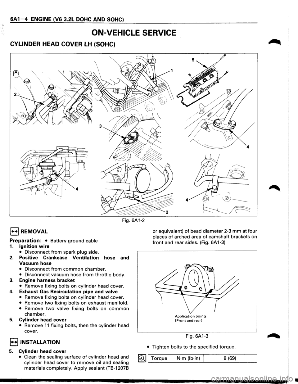
CYLINDER HEAD COVER LH (SOHC)
1••1 REMOVAL
Preparation: • Battery ground cable
1. Ignition wire
• Disconnect from spark plug side.
2. Positive Crankcase Ventilation hose and
Vacuum hose
• Disconnect from common chamber.
• Disconnect vacuum hose from throttle body.
3. Engine harness bracket
• Remove fixing bolts on cylinder head cover.
4. Exhaust Gas Recirculation pipe and valve
• Remove fixing bolts on cylinder head cover.
• Remove two fixing bolts on exhaust manifold.
•
Remove two valve fixing bolts on common
chamber.
5. Cylinder head cover
• Remove 11 fixing bolts, then the cylinder head
cover.
I••IINST ALLA TION
5. Cylinder head cover
• Clean the sealing surface of cylinder head and
cylinder head cover to remove oil and sealing
materials completely.
Apply sealant (TB-12078
/
~
!8;
4
or equivalent) of bead diameter 2-3 mm at four
places of arched area of camshaft brackets on
front and rear sides. (Fig. 6A 1-3)
Application points (Front and rear)
Fig. 6A1-3
• Tighten bolts to the specified torque.
1~1 Torque N·m (lb·in) 8 (69)
•
Page 629 of 1928
ENGINE COOLING 68-1
SECTION 68
ENGINE COOLING
CONTENTS
General Description . . . . . . . . . . . . . . . . . . . . . . . . . . 68-1 Radiator . . . . . . . . . . . . . . . . . . . . . . . . . . . . . . . . . . . . . . 68-7
Diagnosis........................................ 68-3 Drive Belt Adjustment . . . . . . . . . . . . . . . . . . . . 68-1 0
On-Vehicle Service............................ 68-4 Main Data and Specifications .............. 68-12
Water Pump . . . . . . . . . . . . . . . . . . . . . . . . . . . . . . . . 68-4
Thermostat . . . . . . . . . . . . . . . . . . . . . . . . . . . . . . . . . . 68-6
Torque Specifications .................... 68-12
Special Tools ................................... 68-13
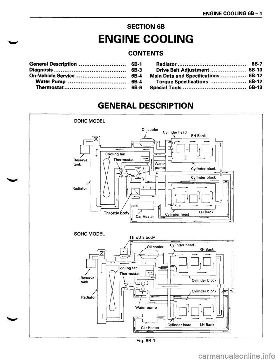
GENERAL DESCRIPTION
DOHC MODEL
Reserve tank
/ Radiator
SOHC MODEL
Radiator
Oil cooler
Throttle body
Fig. 68-1
Cylinder head
"'
RH Bank
' Cylinder bloc~~
Cylinder block
LH Bank
Cylinder block
~
lololol ~ I
~L: - -~,t
Cylinder head LH Bank d
d
Page 632 of 1928
68 - 4 ENGINE COOLING
ON-VEHICLE SERVICE
DRAINING AND REFILLING COOLING
SYSTEM
Before draining the cooling system, inspect the sys
tem and perform any necessary service to ensure that
it is clean, does not leak and is in proper working
order. The Engine Coolant (EC) level should be be
tween the "MIN" and "MAX" lines of reserve tank
when the engine is cold. If low, check for leakage and
add
EC up to the "MAX" line. There should not be any
excessive deposit of rust or scales around the radiator
cap
or radiator filler hole, and the EC should also be
free
from oil. Replace the EC if excessively dirty.
1. Completely drain the cooling system by opening
the drain petcock at the bottom of the radiator.
2. Remove the radiator cap.
W WARNING
To avoid the danger of being burned, do not
remove the cap while the engine and radiator
are still hot. Scalding fluid and steam can be
blown out under pressure.
3. Disconnect all hoses from the EC reserve tank.
Scrub and clean the inside of the reserve tank with
soap and water. Flush it well with clean water,
then drain it. Install the reserve tank and hoses.
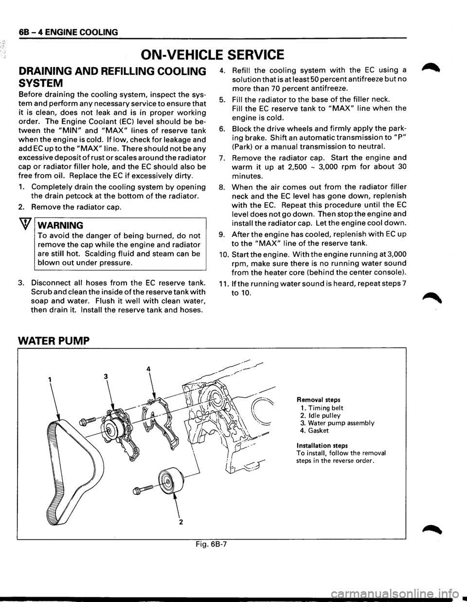
WATER PUMP
3
j
2
4. Refill the cooling system with the EC using a
solution that is at least 50 percent antifreeze but no
more than 70 percent antifreeze.
5. Fill the radiator to the base of the filler neck.
Fill the EC reserve tank to "MAX" line when the
engine is cold.
6. Block the drive wheels and firmly apply the park
ing brake.
Shift an automatic transmission to "P"
(Park) or a manual transmission to neutral.
7. Remove the radiator cap. Start the engine and
warm it up at 2,500 -3,000 rpm for about 30
minutes.
8. When the air comes out from the radiator filler
neck and the EC level has gone down, replenish
with the EC. Repeat this procedure until the EC
level does not go down. Then stop the engine and
install the radiator cap. Let the engine cool down.
9. After the engine has cooled, replenish with EC up
to the "MAX" line of the reserve tank.
10. Start the engine. With the engine running at 3,000
rpm, make sure there is no running water sound
from the heater core (behind the center console).
11. If the running water sound is heard, repeat steps 7
to 10.
Removal steps
1. Timing
belt 2. Idle pulley 3. Water pump assembly
4. Gasket
Installation steps To install, follow the removal steps in the reverse order.
Fig. 6B-7
•
Page 643 of 1928
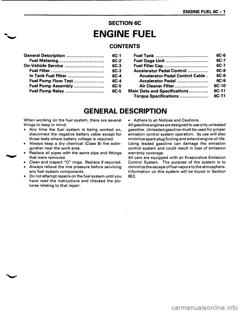
ENGINE FUEL 6C-1
SECTION 6C
ENGINE FUEL
CONTENTS
General Description ....................... .
Fuel Metering ............................ .
On-Vehicle Service ........................ .
Fuel Filter ................................. .
In Tank Fuel Filter ............................. .
Fuel Pump Flow Test ........................ .
Fuel Pump Assembly ........................ .
Fuel Pump Relay .............................. ..
6C-1
6C-2
6C-3
6C-3
6C-4
6C-4
6C-5
6C-5
Fuel Tank .......................................... ..
Fuel Gage Unit ................................. ..
Fuel Filler Cap .................................... .
Accelerator Pedal Control ............... ..
Accelerator Pedal Control Cable ..
Accelerator Pedal ......................... .
Air
Cleaner Filter ........................... .
Main Data and Specifications ............... .
Torque Specifications ......................
..
6C-6
6C-7
6C-7
6C-8
6C-8
6C-9
6C-10
6C-11
6C-11
GENERAL DESCRIPTION
When working on the fuel system, there are several
things to keep in mind:
• Any time the fuel system is being worked on,
disconnect the negative battery
cable except for
those tests where battery voltage is required.
• Always keep a dry chemical (Class 8) fire extin
guisher near the work area.
• Replace all pipes with the same pipe and fittings
that were removed.
• Clean and inspect "0" rings. Replace if required.
• Always relieve the line pressure before servicing
any fuel system components.
• Do not attempt repairs on the fuel system until you
have read the instructions and checked the pic
tures
relating to that repair.
• Adhere to all Notices and Cautions.
All gasoline engines are designed to use only unleaded
gasoline. Unleaded gasoline
must be used for proper
emission control system operation. Its use will also
minimize spark plug fouling and extend engine oil life.
Using leaded gasoline can damage the emission
control system and could result in loss of emission
warranty coverage.
All cars are equipped with an Evaporative Emission
Control System. The purpose of the system is to
minimize the escape offuel vapors to the atmosphere.
Information on this system will be found in Section
6E2.
Page 645 of 1928
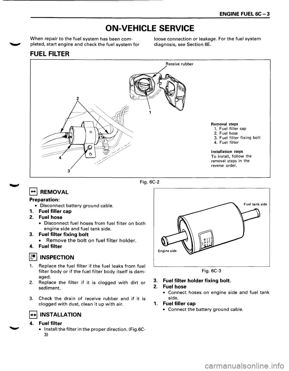
ENGINE FUEL 6C - 3
ON-VEHICLE SERVICE
When repair to the fuel system has been com
pleted, start engine and check the fuel system for
FUEL FILTER
2
3
loose connection or leakage. For the fuel system
diagnosis, see Section 6E.
Receive rubber
Rer:noval steps 1. Fuel filler cap 2. Fuel hose
3. Fuel filter fixing bolt
4. Fuel filter
Installation steps To install, follow the removal steps in the
reverse order.
Fig. 6C-2
EJ REMOVAL
Preparation:
• Disconnect battery ground cable.
1. Fuel filler cap
2. Fuel hose
• Disconnect fuel hoses from fuel filter on both
engine side and fuel tank side.
3. Fuel filter fixing bolt
•
Remove the bolt on fuel filter holder.
4. Fuel filter
(1!] INSPECTION
1. Replace the fuel filter if the fuel leaks from fuel
filter body or if the fuel filter body itself is dam
aged.
2. Replace the filter if it is clogged with dirt or
sediment.
3. Check the drain of receive rubber and if it is
clogged with dust, clean it up with air.
B INSTALLATION
4. Fuel filter
.......,. • Install the filter in the proper direction. (Fig.6C-
3)
Fig. 6C-3
3. Fuel filter holder fixing bolt.
2. Fuel hose
• Connect hoses on engine side and fuel tank
side.
1. Fuel filler cap
• Connect the battery ground cable.