service ISUZU TROOPER 1995 Manual Online
[x] Cancel search | Manufacturer: ISUZU, Model Year: 1995, Model line: TROOPER, Model: ISUZU TROOPER 1995Pages: 1928
Page 655 of 1928
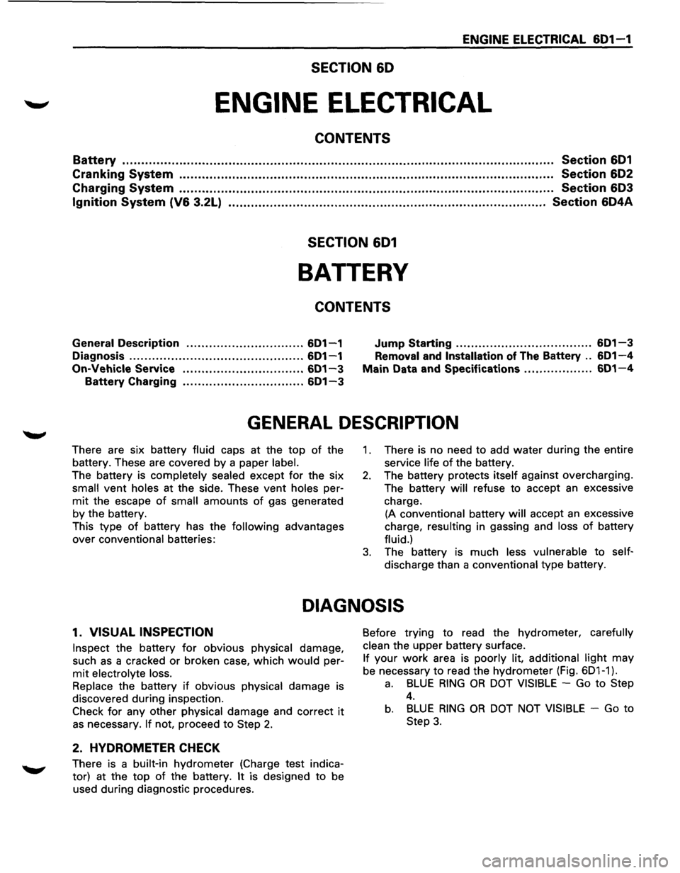
ENGINE ELECTRICAL 601-1
SECTION 60
ENGINE ELECTRICAL
CONTENTS
Battery . . ..... . ...... . ... . .... . .... ..... .... . .... .. .... . .... . . ... . . . .... . . .. . . .... . ... . ... . .... . . .. ... . .... . . ... . ... . . .. . Section 601
Cranking System
........... ... . ... . .... . .... . . .... . .... .
. ... . . .... . .... . .... . . ... ...
.. .... . . ..... . .... . ......... ... Section 602
Charging System ..... .... . . .............. .... . .... . . .. .. . . ... . . ... . . ... . . ... . . ........ .... . . ..... .. .... . ... . .... . .. Section 603
Ignition System (V6 3.2L) .. .... ...... ...... .. .. .. .... ...... .... .. .... .... .... ...... ...... ...... .......... .... Section 6D4A
SECTION 601
BATTERY
CONTENTS
General Description ............................... 6D1-1
Diagnosis .............................................. 6D1-1
On-Vehicle Service ................................ 6D1-3
Battery Charging ................................ 6D1-3
Jump Starting .................................... 6D1-3
Removal and Installation of The Battery . . 6D1-4
Main Data and Specifications . . . . . . . . . . . . . . . . . . 6D1-4
GENERAL DESCRIPTION
There are six battery fluid caps at the top of the
battery. These are covered by a paper
label.
The battery is completely sealed except for the six
small vent holes at the side. These vent holes per
mit the escape of small amounts of gas generated
by the battery.
This type
of battery has the following advantages
over
conventional batteries:
1. There is no need to add water during the entire
service
life of the battery.
2. The battery protects itself against overcharging.
The battery
will refuse to accept an excessive
charge. (A
conventional battery will accept an excessive
charge,
resulting in gassing and loss of battery
fluid.)
3. The battery is much less vulnerable to self
discharge than a conventional type battery.
DIAGNOSIS
1. VISUAL INSPECTION
Inspect the battery for obvious physical damage,
such
as a cracked or broken case, which would per
mit electrolyte loss.
Replace
the battery if obvious physical damage is
discovered during inspection.
Check
for any other physical damage and correct it
as necessary. If not, proceed to Step 2.
2. HYDROMETER CHECK
There is a built-in hydrometer (Charge test indica
tor) at the top of the battery. It is designed to be
used during diagnostic procedures. Before
trying to read the hydrometer,
carefully
clean
the upper battery surface.
If your work area is poorly lit, additional light may
be necessary
to read the hydrometer (Fig. 6D1-1).
a. BLUE RING OR DOT VISIBLE -Go to Step
4.
b. BLUE RING OR DOT NOT VISIBLE -Go to
Step 3.
Page 657 of 1928
ENGINE ELECTRICAL 601-3
ON-VEHICLE SERVICE
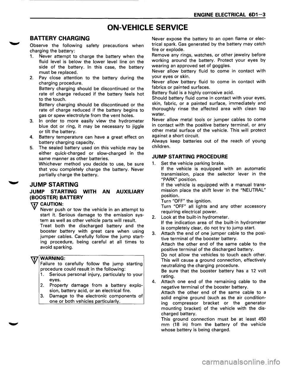
BATTERY CHARGING
Observe the following safety precautions when
charging the battery:
1. Never attempt to charge the battery when the
fluid level is below the lower level line on the
side
of the battery. In this case, the battery
must be replaced.
2. Pay close attention to the battery during the
charging procedure.
Battery charging
should be discontinued or the
rate
of charge reduced if the battery feels hot
to the touch.
Battery charging
should be discontinued or the
rate
of charge reduced if the battery begins to
gas or spew electrolyte from the vent holes.
3. In order to more easily view the hydrometer
blue dot or ring, it may be necessary to jiggle
or tilt the battery.
4. Battery temperature can have a great effect on
battery charging capacity.
5. The sealed battery used on this vehicle may be
either quick-charged or slow-charged in the
same manner
as other batteries.
Whichever method you decide
to use, be sure
that you
completely charge the battery. Never
partially charge the battery.
JUMP STARTING
JUMP STARTING WITH AN AUXILIARY
(BOOSTER)
BATTERY
W CAUTION:
Never push or tow the vehicle in an attempt to
start it.
Serious damage to the emission sys
tem as
well as other vehicle parts will result.
Treat both the discharged battery and the
booster battery
with great care when using
jumper cables. Carefully follow the jump start
ing procedure, being
careful at all times to
avoid sparking.
wwARNING:
Failure to carefully follow the jump starting
procedure
could result in the following:
1. Serious personal injury, particulaly to your
eyes.
2. Property damage from a battery explo
sion, battery acid, or an electrical fire.
3. Damage to the electronic components of
one or both vehicles particularly.
Never expose the battery to an open flame or elec
trical
spark. Gas generated by the battery may catch
fire
or explode.
Remove any rings, watches, or other jewelry before
working around the battery. Protect
your eyes by
wearing
an approved set of goggles.
Never allow battery fluid to come in contact with
your eyes or skin.
Never
allow battery fluid to come in contact with
fabrics or painted surfaces.
Battery
fluid is a highly corrosive acid.
Should battery fluid come in contact with your eyes,
skin, fabric, or a painted surface,
immediately and
thoroughly rinse the affected area with clean tap
water. Never
allow metal tools or jumper cables to come
in contact with the positive battery
terminal, or any
other
metal surface of the vehicle. This will protect
against a short circuit.
Always keep batteries out of the reach of young
children.
JUMP STARTING PROCEDURE
1. Set the vehicle parking brake.
If the vehicle is equipped with an automatic
transmission,
place the selector lever in the
"PARK" position.
If the vehicle is equipped with a manual trans
mission
place the shift lever in the "NEUTRAL"
position.
Turn
"OFF" the ignition.
Turn
"OFF" all lights and any other accessory
requiring
electrical power.
2. Look at the built-in hydrometer.
If the indication area of the built-in hydrometer
is
completely clear, do not try to jump start.
3. Attach the end of one jumper cable to the posi
tive
terminal of the booster battery.
Attach the other end
of the same cable to the
positive
terminal of the discharged battery.
Do not allow the vehicles to touch each other.
This
will cause a ground connection, effectively
neutralizing
the charging procedure.
Be sure that the booster battery has a 12 volt
rating.
4. Attach one end of the remaining cable to the
negative
terminal of the booster battery.
Attach the other end
of the same cable to a
solid engine ground (such as the air condition
ing compressor bracket or the generator
mounting bracket)
of the vehicle with the dis
charged battery.
This ground connection must be at
least 450
mm (18 in) from the battery of the vehicle
whose battery is being charged.
Page 659 of 1928
CRANKING SYSTEM 6D2 - 1
SECTION 602
CRANKING SYSTEM
CONTENTS
General Description ....................... .
Diagnosis
.................................... .
On-Vehicle Service ........................ . 6D2-1
6D2-3
6D2-8 Unit
Repair.................................... 6D2-9
Main Data and Specifications
............ 6D2-17
Torque Specifications
...................... 6D2-18
GENERAL DESCRIPTION
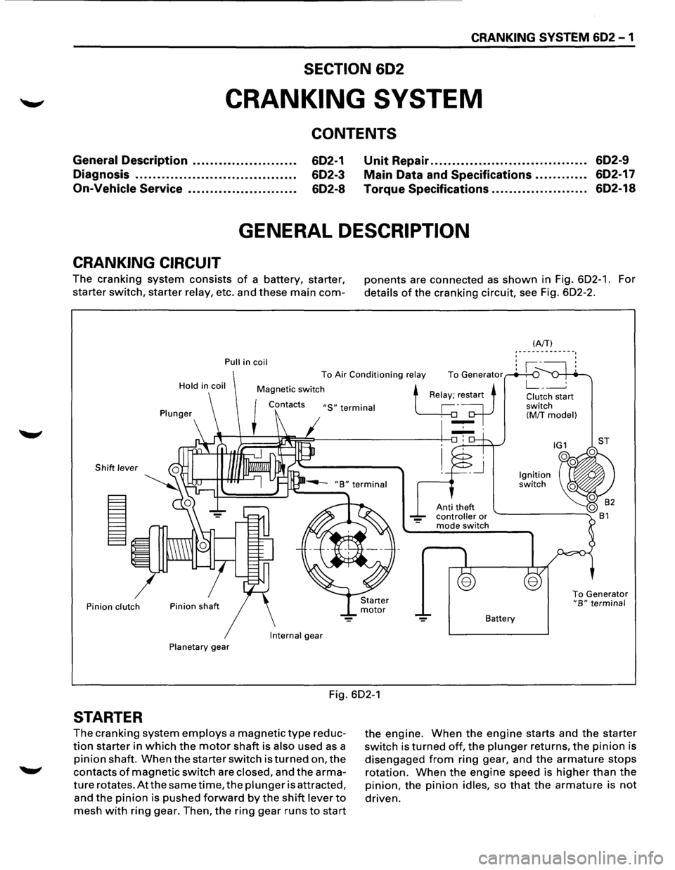
CRANKING CIRCUIT
The cranking system consists of a battery, starter,
starter switch, starter relay, etc. and these main com-
Pull in coil
Hold
in coil
Plunger
Shift lever
Pinion clutch
Internal
gear
Planetary gear
ponents are connected as shown in Fig. 602-1. For
details of the cranking circuit, see Fig. 602-2.
Anti theft controller or mode switch
Battery
(AfT} '-------------. ' '
To Generator "B" terminal
Fig. 602-1
STARTER
The cranking system employs a magnetic type reduc
tion starter in which the motor shaft is also used as a
pinion shaft. When the starter switch is turned on, the
contacts of magnetic switch are closed, and the arma
ture rotates. At the same time, the plunger is attracted,
and the pinion is pushed forward by the shift lever to
mesh with ring gear. Then, the ring gear runs to start
the engine. When the engine starts and the starter
switch is turned off, the plunger returns, the pinion is
disengaged from ring gear, and the armature stops
rotation. When the engine speed is higher than the
pinion, the pinion idles, so that the armature is not
driven.
Page 666 of 1928
602-8 CRANKING SYSTEM
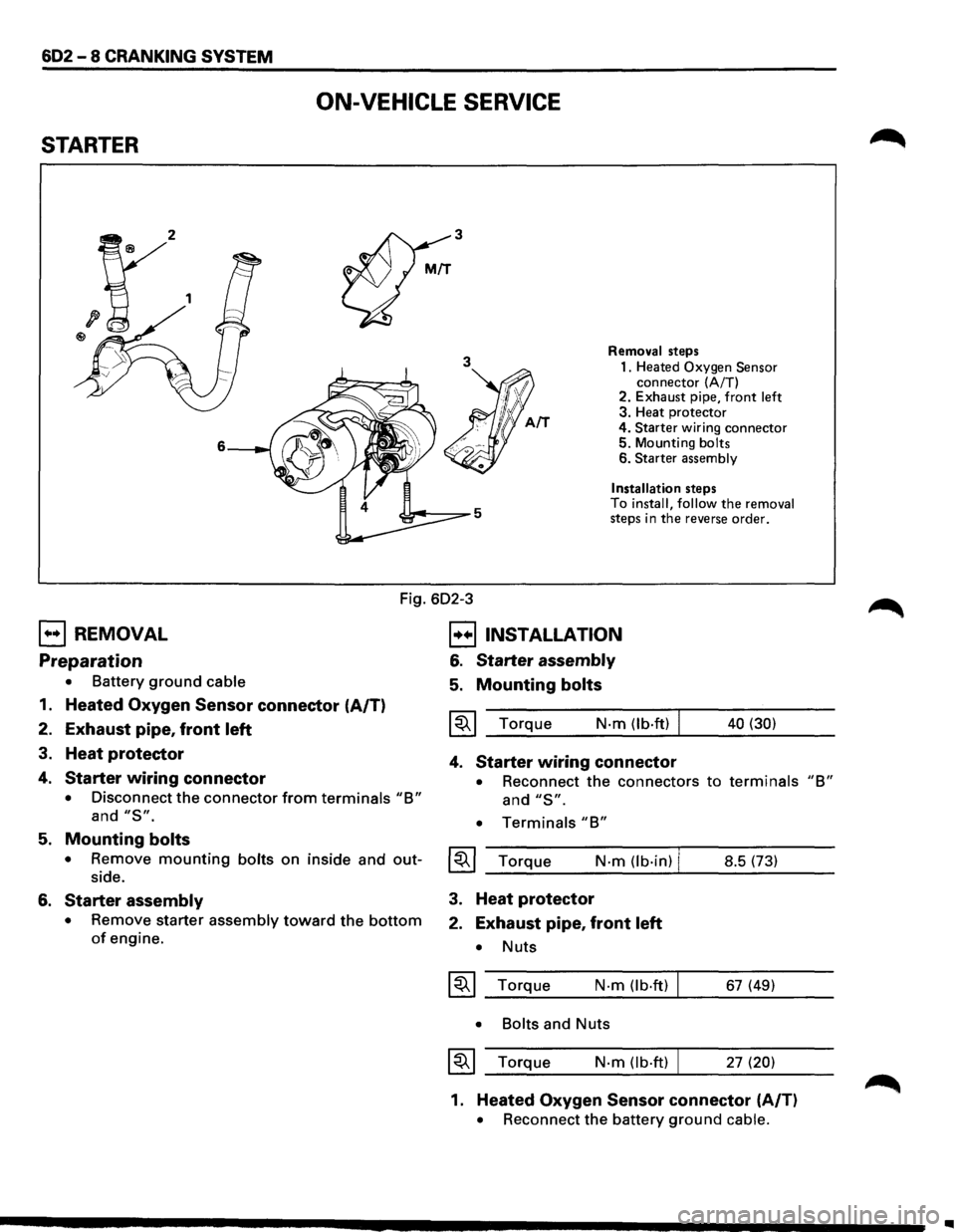
ON-VEHICLE SERVICE
STARTER
3
3
6
Removal steps
1. Heated
Oxygen Sensor connector (A/T)
2. Exhaust pipe, front left 3. Heat protector
4.
Starter wiring connector 5. Mounting bolts 6. Starter assembly
Installation
steps
To install, follow the removal steps in the reverse order.
Fig. 602-3
EJ REMOVAL
Preparation
• Battery ground cable
1. Heated Oxygen Sensor connector (A/T)
2. Exhaust pipe, front left
3. Heat protector
4. Starter wiring connector
• Disconnect the connector from terminals "B"
and "S".
B INSTALLATION
6. Starter assembly
5. Mounting bolts
~~~ Torque N·m (lb·ft) I
4. Starter wiring connector
40 (30)
• Reconnect the connectors to terminals "B"
and "S".
• Terminals "B"
5. Mounting bolts
• Remove mounting bolts on inside and out-~~~ Torque N·m (lb·in) I side. __ _;_ ______ -J.... ______ _ 8.5 (73)
6. Starter assembly
• Remove starter assembly toward the bottom
of engine.
3. Heat protector
2. Exhaust pipe, front left
• Nuts
~~~ Torque N·m (lb.ft)
• Bolts
and Nuts
~~~ Torque N·m (lb·ft) I
67 (49)
27
(20)
1. Heated Oxygen Sensor connector (A/T)
• Reconnect the battery ground cable.
..
Page 677 of 1928
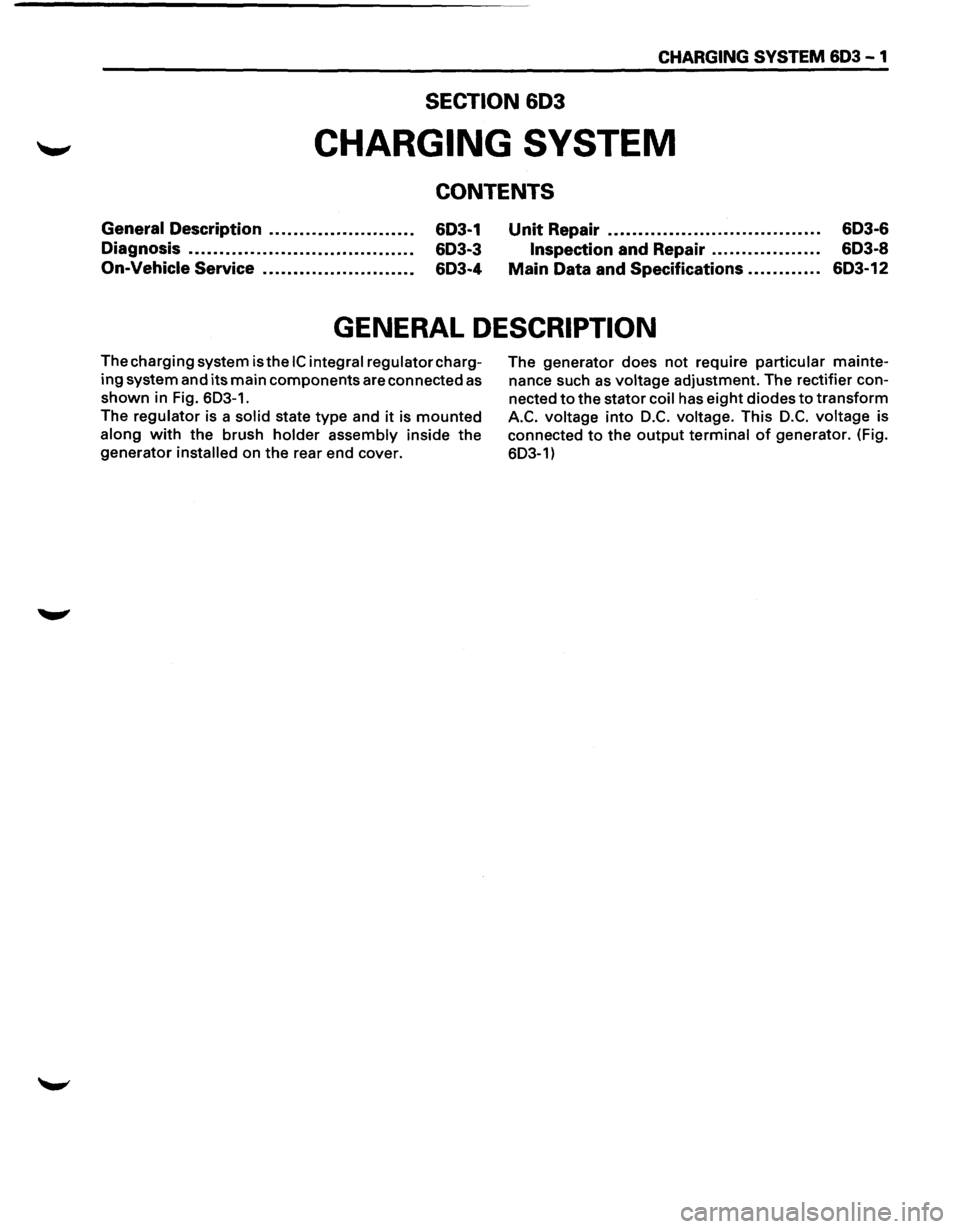
CHARGING SYSTEM 6D3-1
SECTION 603
CHARGING SYSTEM
CONTENTS
General Description ....................... .
Diagnosis
.................................... .
On-Vehicle Service ........................ . 6D3-1
6D3-3
6D3-4 Unit
Repair . . .. .. . . . . . . . . . . . . .. . . . . . . . . . . . . . . . 6D3-6
Inspection and Repair . . . . . . . . . . . . . . . . . . 6D3-8
Main Data and Specifications............ 6D3-12
GENERAL DESCRIPTION
The charging system is the IC integral regulator charg
ing system and its main components are connected as
shown in Fig. 6D3-1.
The regulator is a solid state
type and it is mounted
along with the brush holder assembly inside the
generator installed on the rear end cover. The
generator does not require particular mainte
nance such
as voltage adjustment. The rectifier con
nected
to the stator coil has eight diodes to transform
A.C. voltage into D.C. voltage. This D.C. voltage is
connected
to the output terminal of generator. (Fig.
6D3-1)
Page 680 of 1928
603 - 4 CHARGING SYSTEM
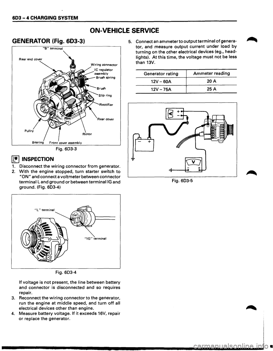
ON-VEHICLE SERVICE
GENERATOR (fig. 603-3}
"B" terminal
Pullry
Fig. 603-3
~ INSPECTION
Wiring connector
I C regulator
assembly
Brush spring
ifier
Rear cover
1. Disconnect the wiring connector from generator.
2. With the engine stopped, turn starter switch to
"ON" and connect a voltmeter between connector
terminal Land ground or between terminaiiG and
ground. (Fig. 603-4)
"IG" terminal
Fig. 603-4
If voltage is not present, the line between battery
and
connector is disconnected and so requires
repair.
3. Reconnect the wiring connector to the generator,
run the
engine at middle speed, and turn off all
electrical
devices other than engine.
4. Measure battery voltage. If it exceeds 16V, repair
or replace the generator.
5. Connect an ammeter to outputterminal of genera
tor, and measure output current under load by
turning on the other electrical devices (eg., head
lights). At this time, the voltage must not be less
than 13V.
Generator rating
Ammeter reading
12V-60A 20A
12V -75A 25A
Fig. 603-5
•
Page 689 of 1928
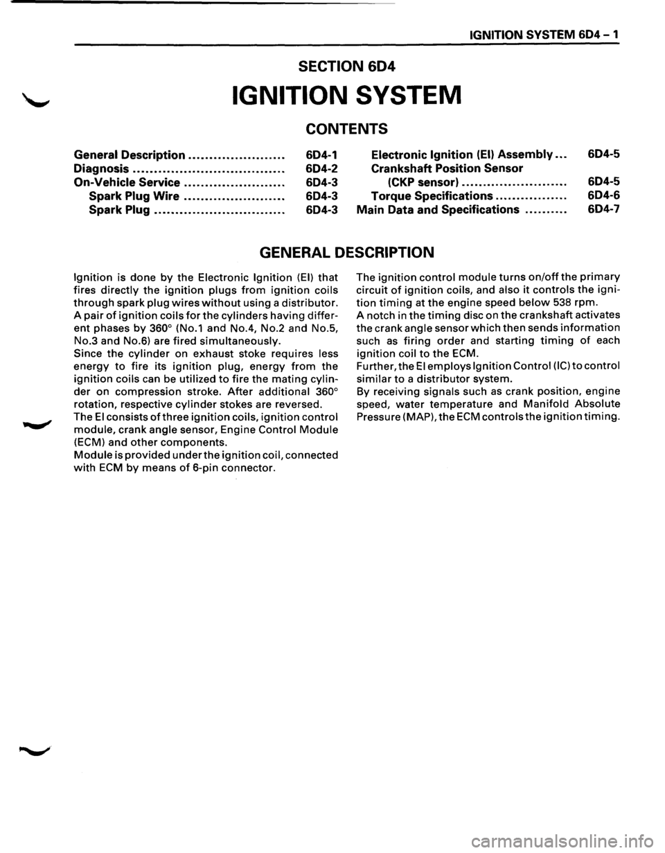
IGNITION SYSTEM 6D4 - 1
SECTION 604
IGNITION SYSTEM
CONTENTS
General Description ...................... .
Diagnosis
................................... .
On-Vehicle Service ....................... .
Spark Plug Wire ....................... .
Spark Plug .............................. . 6D4-1
6D4-2 6D4-3
6D4-3
6D4-3
Electronic Ignition (EI) Assembly ...
Crankshaft Position Sensor
(CKP sensor) ........................ .
Torque Specifications
................ .
Main Data and Specifications
......... . 6D4-5
6D4-5
6D4-6
6D4-7
GENERAL DESCRIPTION
Ignition is done by the Electronic Ignition (EI) that
fires directly the ignition plugs from ignition coils
through spark plug wires without using a distributor.
A pair of ignition coils for the cylinders having differ
ent phases by 360° (No.1 and No.4, No.2 and No.5,
No.3 and No.6) are
fired simultaneously.
Since the cylinder on exhaust stoke requires less
energy to fire its ignition plug, energy from the
ignition coils can be utilized to fire the mating cylin
der on compression stroke. After additional 360°
rotation, respective cylinder stokes are reversed.
TheEl consists of three ignition coils, ignition control
module, crank angle sensor, Engine Control Module
(ECM) and other components.
Module is provided under the ignition coil, connected
with ECM by means of 6-pin connector. The
ignition control module turns on/off the primary
circuit of ignition coils, and also it controls the igni
tion timing at the engine
speed below 538 rpm.
A notch in
the timing disc on the crankshaft activates
the crank angle sensor which then sends information
such as firing order and starting timing of each
ignition coil to the ECM.
Further, the El employs Ignition Control (I C) to control
similar to a distributor system.
By receiving
signals such as crank position, engine
speed, water temperature and Manifold Absolute
Pressure (MAP), the ECM controls the ignition timing.
Page 691 of 1928
![ISUZU TROOPER 1995 Manual Online IGNITION SYSTEM 604 - 3
ON-VEHICLE SERVICE
SPARK PLUG WIRES
EJ REMOVAL
Preparation
• Disconnect battery ground cable.
1. Spark plug wires (Fig. 604-2)
Fig. 6D4-2
(1!] INSPECTION AND REPAIR](/img/61/57183/w960_57183-690.png "ISUZU TROOPER 1995 Manual Online IGNITION SYSTEM 604 - 3
ON-VEHICLE SERVICE
SPARK PLUG WIRES
EJ REMOVAL
Preparation
• Disconnect battery ground cable.
1. Spark plug wires (Fig. 604-2)
Fig. 6D4-2
(1!] INSPECTION AND REPAIR")
IGNITION SYSTEM 604 - 3
ON-VEHICLE SERVICE
SPARK PLUG WIRES
EJ REMOVAL
Preparation
• Disconnect battery ground cable.
1. Spark plug wires (Fig. 604-2)
Fig. 6D4-2
(1!] INSPECTION AND REPAIR
Check the high tension cable for insulation. Check
terminals for corrosion or damage, and replace as
necessary.
Measuring resistance of spark plug wires (kQ)
Spare plug wires SOHC DOHC
No.1 cable 6.4-14.9 6.2-14.2
No.2 cable 5.7-13.1 7.2-16.7
No.3 cable 6.2-14.4 6.5-14.9
No.4 cable 5.8-13.3 6.8-15.8
No.5 cable 6.4-14.9 6.9-16.0
No.6 cable 6.9-16.0 6.3-14.5
Measure resistance
of spark plug wires, and replace
the cable if its value exceeds the standard. (Fig. 6D4-
3)
Fig. 6D4-3
B INSTALLATION
1. Spark plug wires
• Connect ignition coils and spark plugs with
spark plug wires respectively. Match each
number (cylinder No.) marked on the ignition
coil with that on spark plug wire, and connect
each spark
plug for the cylinder. (Fig. 6D4-4)
LH bank
y Front
#4-
#1--
1®®®1
RH Bank
Connecting Position of Spark plug wire
Fig. 6D4-4
• Connect battery ground cable.
"f CAUTION
Do not cross, twist or pull the spark plug wires.
SPARK PLUG
EJ REMOVAL
1. Spare plug wires
2. Spark plugs (Fig. 604-5)
Page 698 of 1928
6E2-2 DRIVEABILITY AND EMISSIONS
DRIVEABILITV AND EMISSIONS GENERAL INFORMATION
CONTENTS
General Information
Driveability ....................... .
Emissions
........................ .
Maintenance
Schedule .............. .
Introduction ...................... .
Electronic Engine
Control .......... .
What This Section Contains ........ .
Blocking Drive Wheels
Visual/Physical
Underhood Inspection
6E2-3
6E2-3
6E2-3
6E2-3
6E2-3
6E2-3
6E2-3
6E2-3
Basic
Knowledge required . . . . . . . . . . . . 6E2-4
Basic Electric Circuits . . . . . . . . . . . . . .
6E2-4
Use
of Circuit Testing Tools . . . . . . . . . 6E2-4
Use
of Digital Volt-Ohm Meter (DVOM). 6E2-4
Diagnostic
Information . . . . . . . . . . . . . . . 6E2-4
"Check Engine" Malfunction Indicator
Lamp (MIL) . . . . . . . . . . . . . . . . . . . . 6E2-4
Intermittent "Check Engine"
Malfunction Indicator Lamp (MIL) . . 6E2-4
Reading Diagnostic
Trouble Codes . . . 6E2-5
Clearing
Trouble Codes . . . . . . . . . . . . 6E2-5
Diagnostic Test
Mode .............. 6E2-5
Engine Control
Module Learning
Ability . . . . . . . . . . . . . . . . . . . . . . . . 6E2-6
Field
Service Mode . . . . . . . . . . . . . . . . 6E2-6
Standard Nomenclature
for Certain
Electrical/Electronic
Components
and Systems . . . . . . . . . . . . . . . . . . . 6E2-6
Abbreviations and Glossary of Terms ..... 6E2-11
Driveability and Emissions
Section Summary ................... 6E2-12
Section .,. A"
Diagnostic Procedure Summary ...... 6E2-13
Data Link Connector
"SCAN Tools" ..... 6E2-14
Data
List (FO) ...................... 6E2-14
"SCAN Tool" Limitations and Use ...... 6E2-14
Intermittent Conditions ............ 6E2-14
"SCAN Tool" Positions ............... 6E2-14
Injector Pulse Width ............... 6E2-14
Closed Loop/Open Loop . . . . . . . . . . . .
6E2-14
Trouble Codes ................... 6E2-14
Throttle Position (TP) Sensor . . . . . . . . 6E2-14
Throttle Angle . . . . . . . . . . . . . . . . . . . 6E2-15 Heated
Oxygen
Sensor (H02S)
Vehicle Speed Sensor (VSS) ....... .
Programmable Read Only Memory ID .
Revolution
Per Minute (RPM) ...... .
Mile Per Hour (MPH) ............. .
Engine
Coolant Temperature (ECT) .. .
Intake Air Temperature (IAT)
Sensor
...................... .
Manifold Absolute Pressure (MAP) .. .
Barometric Pressure (BARO) ....... .
Exhaust Gas Recirculation
(EGR)
(ON/OFF) .................... .
Short Term (S.T.) Fuel Trim and
Long Term
(LT.) Fuel Trim ...... .
Long Term
(LT.) Fuel Trim ........ .
Idle Air Control (lAC) Counts ....... .
Desired Revolution
Per Minute ..... .
Air Conditioning (A/C) Request ..... .
Air Conditioning (A/C) Clutch ...... .
Power Steering Pressure (PSP)
Switch ...................... .
Battery Positive Voltage .......... .
Spark Advance .................. .
Start Up Engine Coolant .......... .
Engine
Speed (RPM) ............. .
Fuel Trim Enable ................ .
Air/Fuel Ratio .................. .
Induction Air Control ............. .
Section B -Driveability Symptoms ... .
Section C -Component Systems .... .
Engine
Control Module (ECM)
and
Sensors .................. .
Fuel Control System ............. .
Electric
Fuel Pump (in-tank) ....... .
Evaporative Emission
(EVAP)
Control System ................ .
Ignition Control (IC) .............. .
Exhaust Gas Recirculator
(EGR) .... .
Air Conditioning (A/C) Clutch Control .
Positive Crankcase Ventilation (PCV) .
Tools Needed
to Service the System .... .
General Specifications
............... .
Vacuum Hose Routing Diagram
........ .
6E2-15
6E2-15
6E2-15
6E2-15
6E2-15
6E2-15
6E2-15
6E2-15
6E2-15
6E2-15
6E2-15
6E2-16
6E2-16
6E2-16
6E2-16
6E2-16
6E2-16
6E2-16
6E2-16
6E2-16
6E2-16
6E2-16
6E2-16
6E2-16
6E2-16
6E2-16
6E2-17
6E2-17
6E2-17
6E2-17
6E2-17
6E2-17
6E2-17
6E2-17
6E2-18
6E2-21
6E2-22
~
... ...
•
Page 699 of 1928
---
DRIVEABILITV AND EMISSIONS 6E2-3
ALL NEW ISUZU VEHICLES ARE CERTIFIED BY THE UNITED STATES ENVIRONMENTAL PROTECTION
AGENCY AS CONFORMING TO THE REQUIREMENTS OF THE REGULATIONS FOR THE CONTROL OF AIR
POLLUTION FROM NEW MOTOR VEHICLES. THIS CERTIFICATION IS CONTINGENT ON CERTAIN
ADJUSTMENTS BEING SET TO FACTORY STANDARDS. IN MOST CASES, THESE ADJUSTMENT POINTS
EITHER HAVE BEEN PERMANENTLY SEALED AND/OR MADE INACCESSIBLE TO PREVENT INDISCRIMINATE
OR ROUTINE ADJUSTMENT IN THE FIELD. FOR THIS REASON, THE FACTORY PROCEDURE FOR
TEMPORARILY REMOVING PLUGS, CAPS, ETC., FOR PURPOSES OF SERVICING THE PRODUCT, MUST BE
STRICTLY FOLLOWED AND, WHEREVER PRACTICABLE, RETURNED TO THE ORIGINAL INTENT OF THE
DESIGN.
GENERAL INFORMATION
DRIVEABILITY
The driveability diagnosis procedures apply to various
systems in current
ISUZU vehicles. The procedures
assume
that the vehicle is worked on properly at one
time and the
problem is due to time, wear, dirt or other
causes.
Start with the introduction that follows. This
will describe a systematic diagnostic procedure.
Any system disconnected during diagnosis should be
reconnected. This
includes wires, hoses, linkage, etc.
EMISSIONS
The exhaust emission control systems used on
ISUZU engines perform a specific function to lower
exhaust emissions while maintaining good fuel
economy and driveability.
MAINTENANCE SCHEDULE
Refer to the Maintenance Schedule in Section "OB"
General Information for the maintenance service that
should be performed to retain emission control
performance.
INTRODUCTION
ELECTRONIC ENGINE CONTROL
All engines have an Engine Control Module (ECM)
to control the fuel system. The ECM varies the air/
fuel ratio by controlling the fuel flow through the
injectors.
In addition, the ECM controls the ignition timing,
fuel pump, and various other systems.
It is important to review the component sections
and
wiring diagrams in this Section for specific
components
controlled by the ECM and what
systems are non-ECM controlled.
WHAT THIS SECTION CONTAINS
Each ISUZU engine has system controls to reduce
exhaust emissions
while maintaining good
driveability and fuel economy. •
This Section explains:
•
How to use the Driveability and Emission
Section
"6E2" engines.
• A brief description of systems used to
control fuel and emissions.
• Abbreviations that are used in Driveability
and Emissions.
• Special tools used to diagnosis and repair a
system.
Before checking the
system, adhere to the
following information:
BLOCKING DRIVE WHEELS
The vehicle drive wheels should always be
blocked, and parking brake firmly set, while
checking the system.
VISUAL/PHYSICAL UNDERHOOD
INSPECTION
A careful visual and physical underhood
inspection must
be performed as part of any
diagnostic procedure
or in finding the cause of an
emissions test failure. This can often lead to fixing
a
problem without further steps. Inspect all
vacuum hoses for correct routing, pinches, cuts,
or disconnections. Be sure to inspect hoses that
are
difficult to see beneath the throttle body and
common chamber.
Inspect all the wires in the
engine
compartment for correct and good
connections, burned or chaffed spots, pinched
wires, or contact with sharp edges or hot exhaust
manifolds. This visual/physical inspection is very
important. It must be done carefully and
thoroughly.