service ISUZU TROOPER 1995 Repair Manual
[x] Cancel search | Manufacturer: ISUZU, Model Year: 1995, Model line: TROOPER, Model: ISUZU TROOPER 1995Pages: 1928
Page 408 of 1928
5A3-40 REAR WHEEL ANTILOCK BRAKE SYSTEM
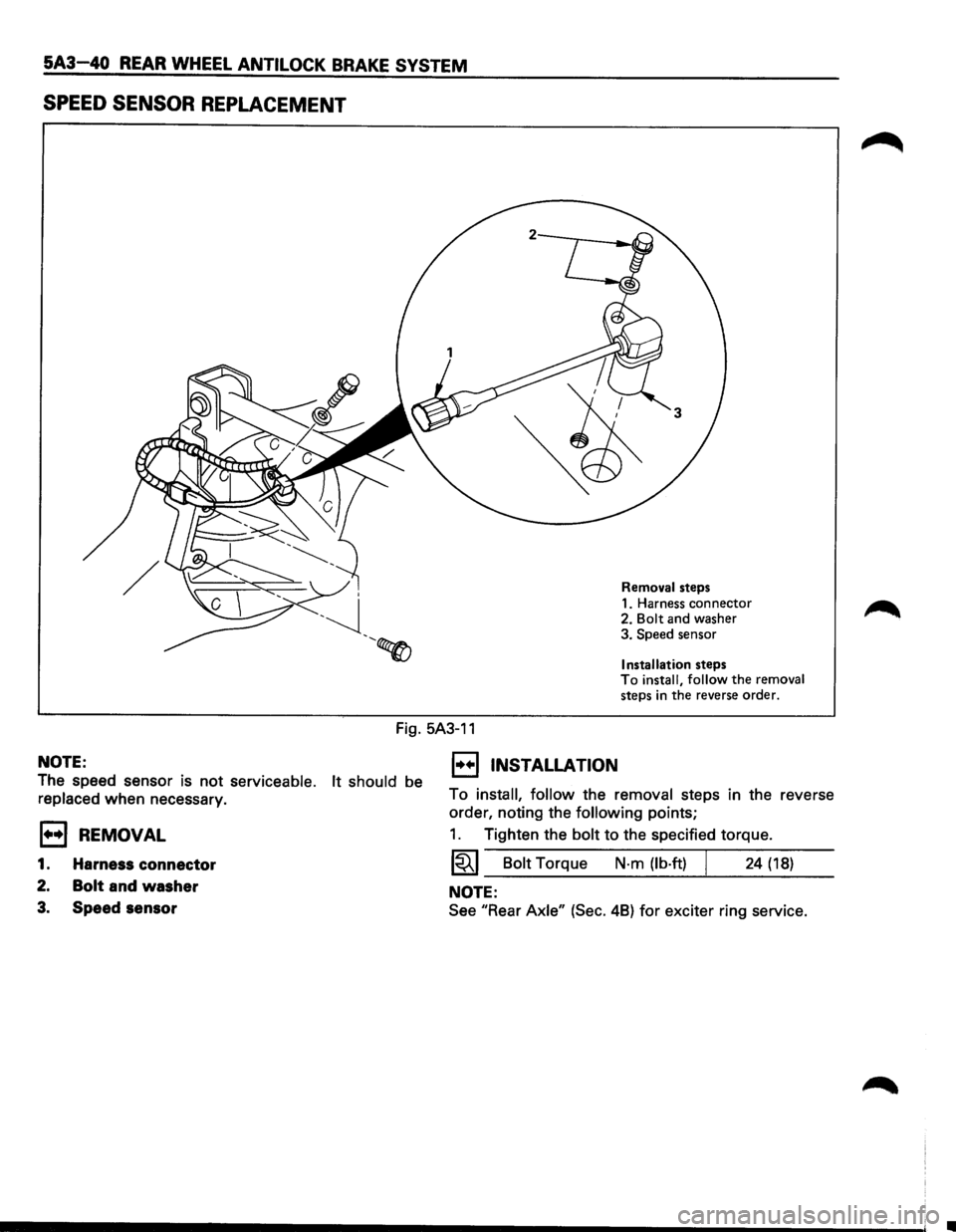
SPEED SENSOR REPLACEMENT
Removal steps
1. Harness connector
2.
Bolt and washer
3. Speed sensor
Installation steps To install, follow the removal
steps in the reverse order.
Fig. 5A3-11
NOTE:
The speed sensor is not serviceable. It should be
replaced when necessary.
E3 REMOVAL
1. Harness connector
2. Bolt and washer
3. Speed sensor
1••1 INSTALLATION
To install, follow the removal steps in the reverse
order, noting the
following points;
1. Tighten the bolt to the specified torque.
1~1 Bolt Torque N-m {lb·ft) I 24 {18)
NOTE:
See "Rear Axle" {Sec. 48) for exciter ring service.
Page 411 of 1928
4-WHEEL ANTILOCK BRAKE SYSTEM (ABS) 5A4-1
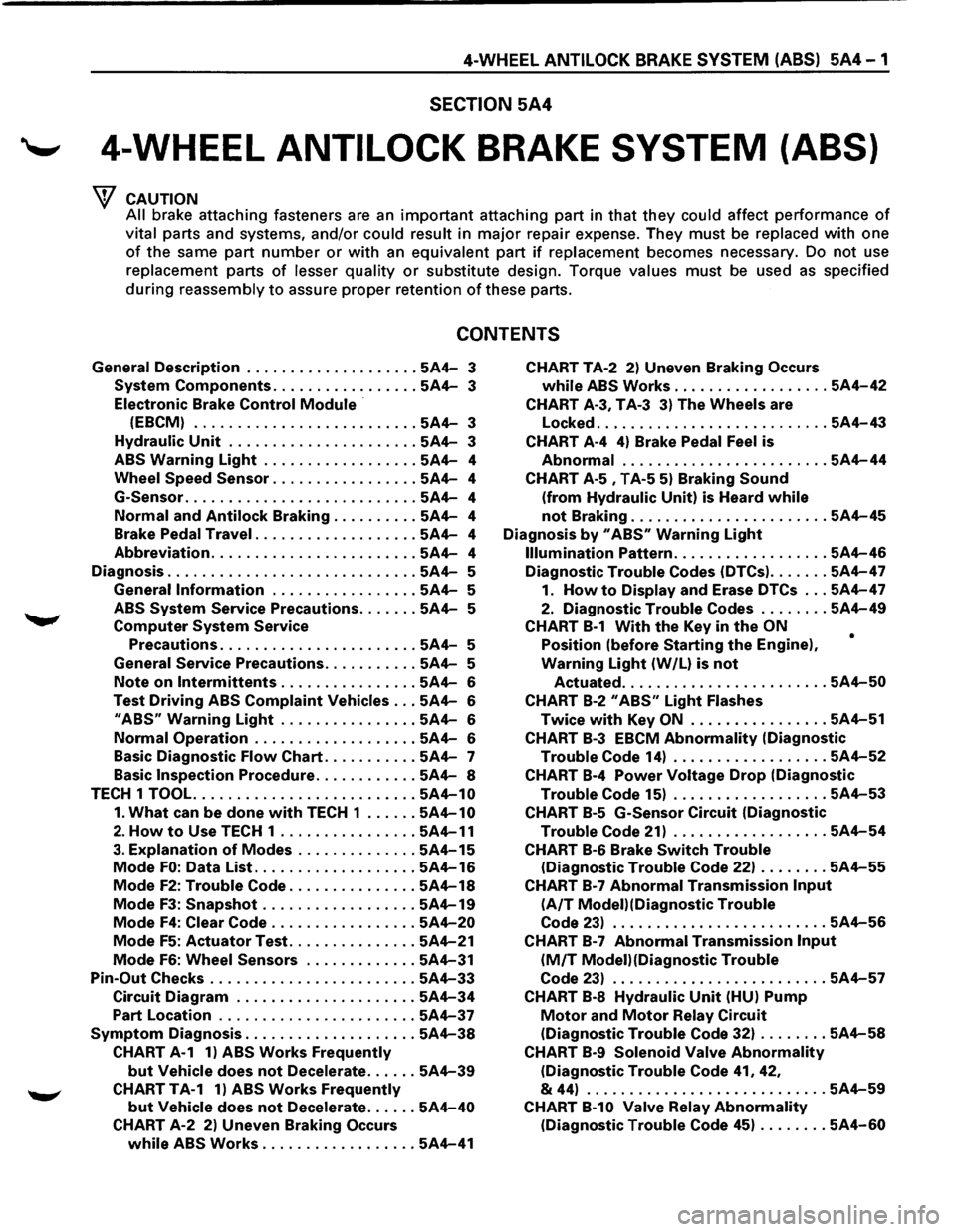
SECTION 5A4
'--' 4-WHEEL ANTILOCK BRAKE SYSTEM (ABS)
CAUTION
All
brake attaching fasteners are an important attaching part in that they could affect performance of
vital parts and systems, and/or could result in major repair expense. They must be replaced with one
of the same part number or with an equivalent part if replacement becomes necessary. Do not use
replacement parts
of lesser quality or substitute design. Torque values must be used as specified
during reassembly to assure proper retention of these parts.
CONTENTS
General Description .................... 5A4-3
System Components ................. 5A4-3
Electronic Brake
Control Module ·
(EBCM) .......................... 5A4-3
Hydraulic Unit ...................... 5A4-3
ABS Warning Light .................. 5A4-4
Wheel
Speed Sensor ................. 5A4-4
G-Sensor
........................... 5A4-4
Normal and Antilock Braking .......... 5A4-4
Brake Pedal Travel
................... 5A4-4
Abbreviation ........................ 5A4-4
Diagnosis
............................. 5A4-5
General
Information ................. 5A4-5
ABS
System Service Precautions ....... 5A4-5
Computer System Service
Precautions
....................... 5A4-5
General Service Precautions
........... 5A4-5
Note on lntermittents ................ 5A4-6
Test Driving ABS Complaint Vehicles ... 5A4-6
II ABS11 Warning Light ................ 5A4-6
Normal Operation ................... 5A4-6
Basic
Diagnostic Flow Chart ........... 5A4-7
Basic
Inspection Procedure ............ 5A4-8
TECH 1
TOOL. ......................... 5A4-10
1. What can be done with TECH 1 ...... 5A4-10
2. How to Use TECH 1 ................ 5A4-11
3. Explanation of Modes .............. 5A4-15
Mode FO: Data List ................... 5A4-16
Mode F2: Trouble Code ............... 5A4-18
Mode F3: Snapshot .................. 5A4-19
Mode F4: Clear Code ................. 5A4-20
Mode F5: Actuator Test ............... 5A4-21
Mode F6: Wheel Sensors ............. 5A4-31
Pin-Out Checks ........................ 5A4-33
Circuit Diagram ..................... 5A4-34
Part Location ....................... 5A4-37
Symptom Diagnosis .................... 5A4-38
CHART A-1 1) ABS Works Frequently
but Vehicle does not Decelerate ...... 5A4-39
CHART TA-1 1) ABS Works Frequently
but Vehicle does not Decelerate ...... 5A4-40
CHART A-2 2) Uneven Braking Occurs
while ABS Works .................. 5A4-41
CHART TA-2 2) Uneven Braking Occurs
while ABS Works .................. 5A4-42
CHART A-3, T A-3 3) The Wheels are
Locked
........................... 5A4-43
CHART A-4 4) Brake Pedal Feel is
Abnormal ........................ 5A4-44
CHART A-5 , T A-5 5) Braking Sound
(from Hydraulic Unit) is Heard while
not Braking ....................... 5A4-45
Diagnosis by 11 ABS11 Warning Light
Illumination Pattern .................. 5A4-46
Diagnostic Trouble Codes (DTCs) ....... 5A4-47
1. How to Display and Erase DTCs ... 5A4-47
2. Diagnostic Trouble Codes ........ 5A4-49
CHART B-1 With the Key in the ON
Position (before Starting the Engine),
Warning Light (W /L) is not
•
Actuated ........................ 5A4-50
CHART B-2 II ABSII Light Flashes
Twice with Key ON ................ 5A4-51
CHART B-3 EBCM Abnormality (Diagnostic
Trouble Code 14) .................. 5A4-52
CHART B-4 Power Voltage Drop (Diagnostic
Trouble Code 15) .................. 5A4-53
CHART B-5 G-Sensor Circuit (Diagnostic
Trouble Code 21) .................. 5A4-54
CHART B-6 Brake Switch Trouble
(Diagnostic Trouble Code 22) ........ 5A4-55
CHART B-7 Abnormal Transmission Input
(A/T Modei)(Diagnostic Trouble
Code 23) ......................... 5A4-56
CHART B-7 Abnormal Transmission Input
(M/T Modei)(Diagnostic Trouble
Code 23) ......................... 5A4-57
CHART B-8 Hydraulic Unit (HU) Pump
Motor and Motor Relay Circuit
(Diagnostic Trouble Code 32) ........ 5A4-58
CHART B-9 Solenoid Valve Abnormality
(Diagnostic Trouble Code 41, 42,
& 44) ............................ 5A4-59
CHART B-10 Valve Relay Abnormality
(Diagnostic Trouble Code 45) ........ 5A4-60
Page 412 of 1928
5A4-2 4-WHEEL ANTILOCK BRAKE SYSTEM (ABS)
CHART B-11 Speed Sensor Disconnection
(Diagnostic
Trouble Code
51, 52, 53, & 54) ................... 5A4-61
CHART B-12 Speed Sensor Short Circuit
(Diagnostic Trouble Code
61, 62,
63,
& 64) ................... 5A4-62
CHART B-13, TB-13 Sensor Signal Input
Abnormality (Diagnostic Trouble
Code
65) ......................... 5A4-63
Unit Inspection Procedure ............... 5A4-64
CHART C-1 G-Sensor Unit Inspection
Procedure ........................ 5A4-65
CHART C-2 Sensor Output Inspection
Procedure ........................ 5A4-66
CHART TC-2 Sensor Output Inspection
Procedure ........................ 5A4-67
CHART C-3 4WD Switch Inspection
Procedure ........................ 5A4-68
CHART TC-3 4WD Switch Inspection
Procedure ........................ 5A4-69
CHART C-4 Transmission Input
Inspection Procedure (A/T Modell .... 5A4-70
CHART C-4 Transmission Input
Inspection Procedure (M/T Model) .... 5A4-71
CHART TC-4 Transmission Input
Inspection Procedure ............... 5A4-72
On-Vehicle Service ..................... 5A4-73
Hydraulic Unit ...................... 5A4-73
Electronic Brake Control Module
(EBCMI .......................... 5A4-74
G-Sensor ........................... 5A4-75
Front Wheel Speed Sensor ............ 5A4-76
Rear
Wheel Speed Sensor ............ 5A4-78
Special Tools .......................... 5A4-79
..
Page 415 of 1928
4-WHEEL ANTILOCK BRAKE SYSTEM (ABS) 5A4-5
DIAGNOSIS
GENERAL INFORMATION
ABS troubles can be classified to two types, those
which can be detected by the ABS warning light
and those which can be detected as a vehicle
abnormality by the driver.
In either case, locate the fault in accordance with
the "BASIC DIAGNOSTIC FLOWCHART" and repair.
Please refer to Section 5A, 5A1, 5A2, 5C for the
diagnosis
of mechanical troubles such as brake
noise, brake
judder (brake pedal or vehicle vibration
felt when braking), uneven braking, and parking
brake
trouble.
ABS SYSTEM SERVICE PRECAUTIONS
Required Tools and Items
Box Wrench
• Brake Fluid
Special Tool
Some diagnosis procedures in this section require
the installation of a special tool.
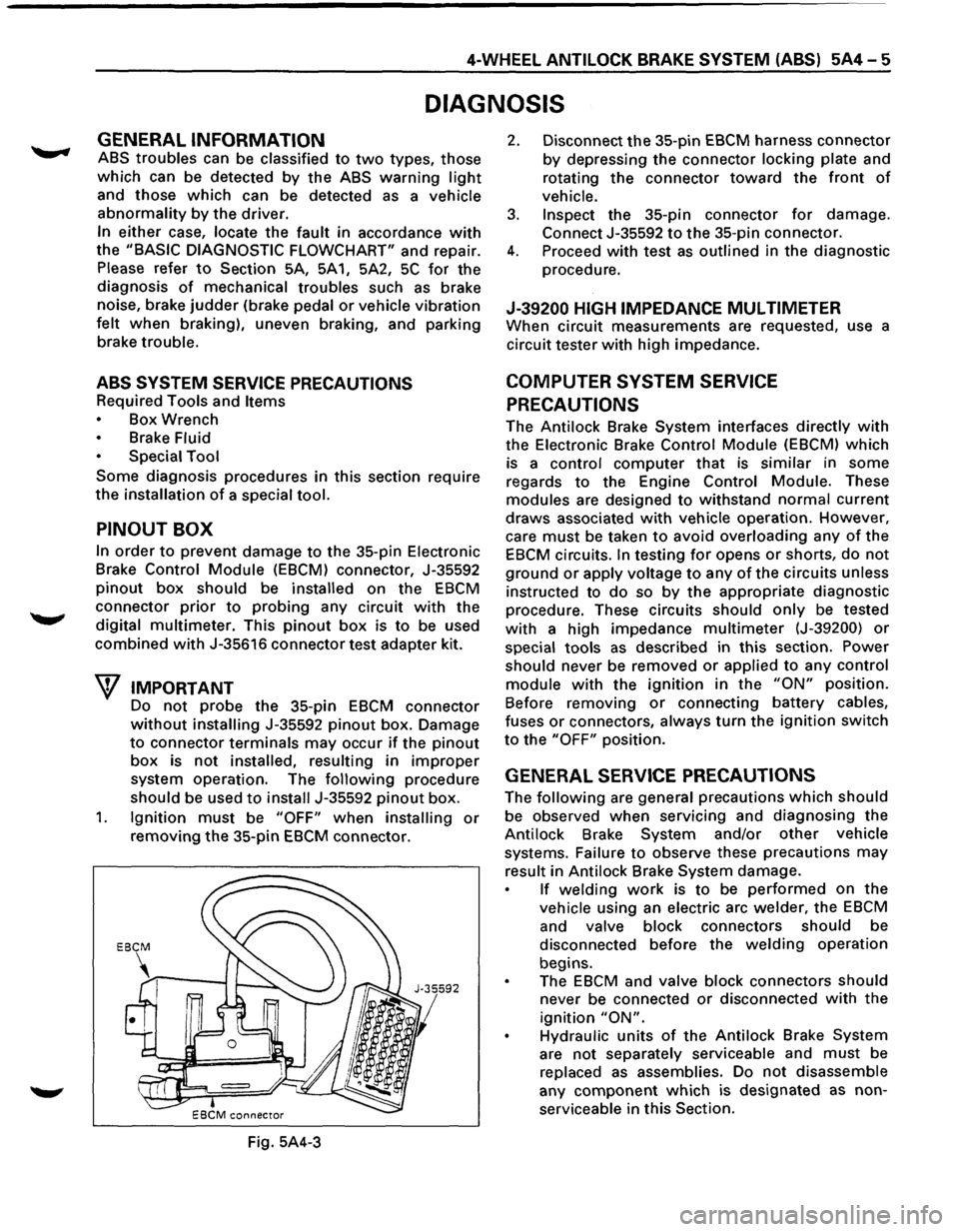
PINOUT BOX
In order to prevent damage to the 35-pin Electronic
Brake
Control Module (EBCM) connector, J-35592
pinout box should be installed on the EBCM
connector prior to probing any circuit with the
digital
multimeter. This pinout box is to be used
combined with J-35616 connector test adapter kit.
W IMPORTANT
Do not probe the 35-pin EBCM connector
without installing J-35592 pinout box. Damage
to connector terminals may occur if the pinout
box is not installed, resulting in improper
system operation. The following procedure
should be used to install J-35592 pinout box.
1. Ignition must be "OFF" when installing or
removing the 35-pin EBCM connector.
Fig. 5A4-3
2. Disconnect the 35-pin EBCM harness connector
by depressing the connector locking plate and
rotating
the connector toward the front of
vehicle.
3. Inspect the 35-pin connector for damage.
Connect J-35592 to the 35-pin connector.
4. Proceed with test as outlined in the diagnostic
procedure.
J-39200 HIGH IMPEDANCE MUL TIMETER
When circuit measurements are requested, use a
circuit tester
with high impedance.
COMPUTER SYSTEM SERVICE
PRECAUTIONS
The Antilock Brake System interfaces directly with
the Electronic Brake Control Module (EBCM) which
is a
control computer that is similar in some
regards
to the Engine Control Module. These
modules are designed to withstand normal current
draws associated with vehicle operation. However,
care
must be taken to avoid overloading any of the
EBCM circuits. In testing for opens or shorts, do not
ground or apply voltage to any of the circuits unless
instructed to
do so by the appropriate diagnostic
procedure. These circuits should only be tested
with a high impedance multimeter (J-39200) or
special tools as described in this section. Power
should never be removed or applied to any control
module with the ignition in the "ON" position.
Before removing
or connecting battery cables,
fuses
or connectors, always turn the ignition switch
to the "OFF" position.
GENERAL SERVICE PRECAUTIONS
The following are general precautions which should
be observed when servicing and diagnosing the
Antilock Brake System and/or
other vehicle
systems. Failure
to observe these precautions may
result in Antilock Brake System damage.
If welding work is to be performed on the
vehicle using an electric arc welder, the EBCM
and valve block connectors should be
disconnected before the
welding operation
begins.
The
EBCM and valve block connectors should
never be connected or disconnected with the
ignition "ON".
Hydraulic units of the Antilock Brake System
are not separately serviceable and must be
replaced
as assemblies. Do not disassemble
any
component which is designated as non
serviceable in
this Section.
Page 418 of 1928
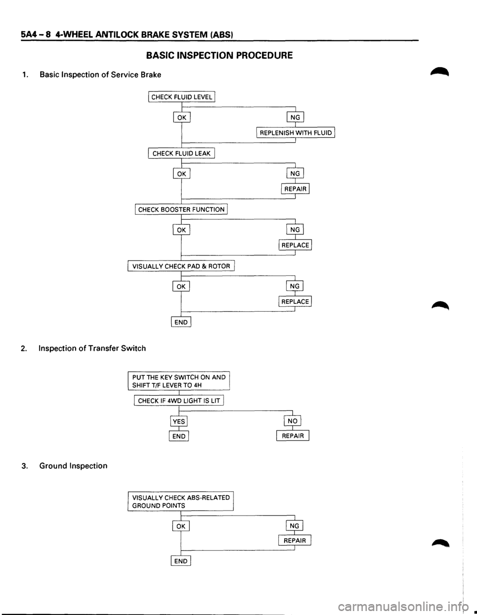
5A4-8 4-WHEEL ANTILOCK BRAKE SYSTEM (ABS)
BASIC INSPECTION PROCEDURE
1. Basic Inspection of Service Brake
VISUALL V CHECK PAD & ROTOR
2. Inspection of Transfer Switch
3. Ground Inspection
PUT THE KEY SWITCH ON AND
SHIFT T/F LEVER TO 4H
CHECK IF 4WD LIGHT IS LIT
VISUALL
V CHECK ASS-RELATED
GROUND POINTS
•
Page 483 of 1928
4-WHEEL ANTILOCK BRAKE SYSTEM (ABS) 5A4-73
ON-VEHICLE SERVICE
W CAUTION:
~ Replace all components included in repair kits used to service this system. Lubricate rubber parts with
clean, fresh brake fluid to ease assembly. Do not use shop air with in-line lubricators on brake parts,
as
damage to rubber components may result. If any hydraulic component is removed or brake line
disconnected,
it may be necessary to bleed part or all of the brake system.
NOTE:
The use of rubber hoses or parts other than those furnished specifically for the Anti lock Brake System may
lead to functional problems requiring major overhaul.
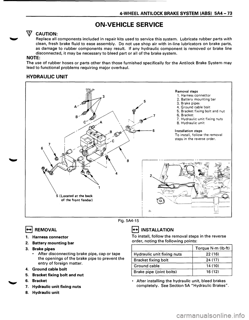
HYDRAULIC UNIT
5 (Located at the back
of the front fender) Removal
steps
1. Harness connector 2. Battery mounting bar 3. Brake pipes 4. Ground cable bolt 5. Bracket fixing bolt and nut 6. Bracket 7. Hydraulic unit fixing nuts 8. Hydraulic unit
Installation steps To install, follow the removal
steps in the reverse order.
1••1 REMOVAL
Fig. 5A4-15
I••IINSTALLATION
1. Harness connector
2. Battery mounting bar
3. Brake pipes
• After disconnecting brake pipe, cap or tape
the
openings of the brake pipe to prevent the
entry of foreign matter.
4. Ground cable bolt
5. Bracket fixing bolt and nut
6. Bracket
7. Hydraulic unit fixing nuts
8. Hydraulic unit
To install, follow the removal steps in the reverse
order,
noting the following points:
Torque
N·m Ob·ftl
Hydraulic unit fixing nuts 22 (16)
Bracket fixing bolt 24 (17)
Ground cable 14 (10)
Brake pipe (joint bolts) 16 (12)
• After installing the hydraulic unit, bleed brakes
completely.
See Section 5A "Hydraulic Brakes".
Page 491 of 1928
PARKING BRAKES 5C-1
SECTION 5C
PARKING BRAKES
'\f7 CAUTION:
Yf All brake attaching fasteners are an important attaching part in that they could affect performance of vital
parts and systems, and/or could result in major repair expense. They must be replaced with one ofthe same
part number
or with and equivalent part if replacement becomes necessary. Do not use replacement parts of
lesser quality or substitute design. Torque values must be used as specified during reassembly to assure
proper retention
of these parts.
CONTENTS
General Description ..................... 5C-1
Operation . . . . . . . . . . . . . . . . . . . . . . . . . . . . . 5C-2
On-Vehicle Service
..................... 5C-3
Parking Brake Lever Replacement . .
. . . . .
5C-3
Parking Brake Front Cable . .
. . . . . . . . . . .
5C-4
Parking Brake Rear Cable . .
. . . . . . . . . . . .
5C-5
Parking Brake Lining Inspection ......... 5C-6
Parking Brake Rotor (Drum) Inspection ... 5C-6
Parking Brake Adjustment .............. 5C-7
Main Data and Specifications ............. 5C-8
General
Specifications ................. 5C-8
Torque Specifications ................. 5C-8
GENERAL DESCRIPTION
Pulling up the parking brake lever by hand will set the
parking brake.
Once pulled up, the lever is held by a
ratchet type
lock until it is released. The position of the
lever is transmitted through cable/lever systems to the
rear
wheels. These parts are designed to obtain
sufficient braking force
when parking on slopes. When
the parking brake is set,
or when the ignition SW is in
the
"ON" position, the brake warning light illuminates.
The rear wheel parking brake is a duo-servo brake
(mechanical inside expansion type) built in to the rear
disc brake. Parking brake adjustment is made through
the adjusting
hole (bored through back plate). Parking
brake
lever stroke should be adjusted to 6 or 7
notches. Refer
to "Parking Brake Adjustment" in
this Section.
Page 493 of 1928
~
PARKING BRAKES SC-3
ON-VEHICLE SERVICE
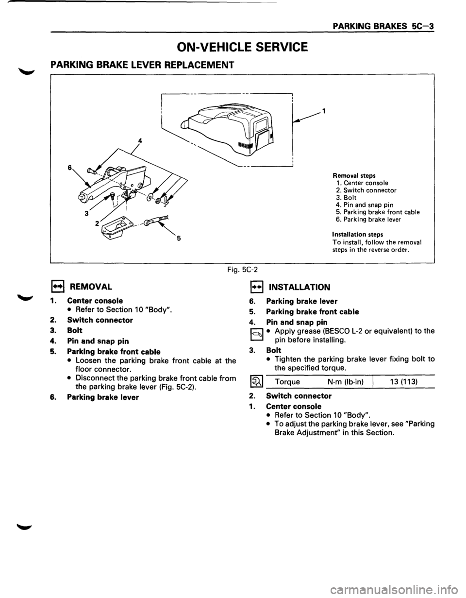
PARKING BRAKE LEVER REPLACEMENT
1
4
6
Removal steps
1. Center console
2. Switch
connector 3. Bolt
4. Pin and snap pin
5. Parking brake
front cable 6. Parking brake lever
Installation
steps
To install, follow the removal
steps in the reverse order.
Fig. 5C-2
l••l REMOVAL
1.
2.
3.
4.
5.
Center console
• Refer to Section 1 0 "Body".
Switch connector
Bolt
Pin and snap pin
Parking brake front
cable
• Loosen the parking brake front cable at the
floor connector.
• Disconnect the parking brake front cable from
the parking brake lever (Fig. 5C-2).
6. Parking brake lever
1••1 INSTALLATION
6. Parking brake lever
5. Parking brake front cable
4. Pin and snap pin
r:::J • Apply grease (BESCO L-2 or equivalent) to the
D pin before installing.
3. Bolt
• Tighten the parking brake lever fixing bolt to
the specified torque.
~~~ Torque N·m (lb·in) 13 (113)
2. Switch connector
1. Center console
• Refer to Section 10 "Body".
•
To adjust the parking brake lever, see "Parking
Brake Adjustment" in this Section.
Page 499 of 1928
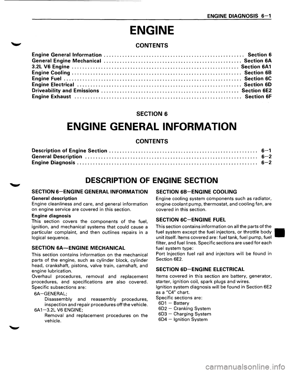
ENGINE DIAGNOSIS S-1
ENGINE
CONTENTS
Engine General Information . . . . . . . . . . . . . . . . . . . . . . . . . . . . . . . . . . . . . . . . . . . . . . . . . . . . . Section S
General
Engine Mechanical .................................................... Section SA
3.2L VS Engine ............................................................... Section SA1
Engine Cooling . . . . . . . . . . . . . . . . . . . . . . . . . . . . . . . . . . . . . . . . . . . . . . . . . . . . . . . . . . . . . . . . Section S8
Engine Fuel . . . . . . . . . . . . . . . . . . . . . . . . . . . . . . . . . . . . . . . . . . . . . . . . . . . . . . . . . . . . . . . . . . . Section SC
Engine Electrical . . . . . . . . . . . . . . . . . . . . . . . . . . . . . . . . . . . . . . . . . . . . . . . . . . . . . . . . . . . . . . Section SD
Driveability and Emissions . . . . . . . . . . . . . . . . . . . . . . . . . . . . . . . . . . . . . . . . . . . . . . . . . . . . Section SE2
Engine Exhaust . . . . . . . . . . . . . . . . . . . . . . . . . . . . . . . . . . . . . . . . . . . . . . . . . . . . . . . . . . . . . . . Section SF
SECTION 6
ENGINE GENERAL INFORMATION
CONTENTS
Description of Engine Section . . . . . . . . . . . . . . . . . . . . . . . . . . . . . . . . . . . . . . . . . . . . . . . . . . . . . . . . S-1
General Description . . . . . . . . . . . . . . . . . . . . . . . . . . . . . . . . . . . . . . . . . . . . . . . . . . . . . . . . . . . . . . . . . S-2
Engine Diagnosis . . . . . . . . . . . . . . . . . . . . . . . . . . . . . . . . . . . . . . . . . . . . . . . . . . . . . . . . . . . . . . . . . . . . S-2
DESCRIPTION OF ENGINE SECTION
SECTIONS-ENGINE GENERAL INFORMATION SECTION S8-ENGINE COOLING
General description
Engine cleanliness and care, and general information
on engine service are covered in this section.
Engine diagnosis
This section covers the components of the fuel,
ignition, and mechanical systems that could cause a
particular complaint, and then outlines repairs in a
logical sequence.
SECTION SA-ENGINE MECHANICAL
This section contains information on the mechanical
parts of the engine, such as cylinder block, cylinder
head, crankshaft, pistons, valve train, camshaft, and
engine
lubrication.
Overhaul
procedures, removal and replacement
procedures, and specifications are also covered.
Specific subsections are:
SA-GENERAL;
Disassembly and reassembly procedures,
inspection and repair procedures
off the vehicle.
6A 1-3.2L V6 ENGINE;
Removal
and replacement procedures on the
vehicle.
Engine cooling system components such as radiator,
engine
coolant pump, thermostat, and cooling fan, are
covered
in this section.
SECTION SC-ENGINE FUEL
This section contains information on all the parts of the
fuel system except the fuel injectors, or throttle body II
unit itself. Items covered are: fuel tank, fuel pump, fuel
filter,
and fuel lines. Specific sections are used for each
fuel system type:
Port
Injection fuel rail and injectors will be found in
Section
6E2.
SECTION SD-ENGINE ELECTRICAL
Items covered in this section are battery, generator,
starter, ignition
coil, spark plugs and wires.
Ignition system diagnosis will be found in Section 6E2
as a "C4" chart.
Specific sections are:
601 -Battery
602 - Cranking System
603 -Charging System
604 -Ignition System
Page 500 of 1928
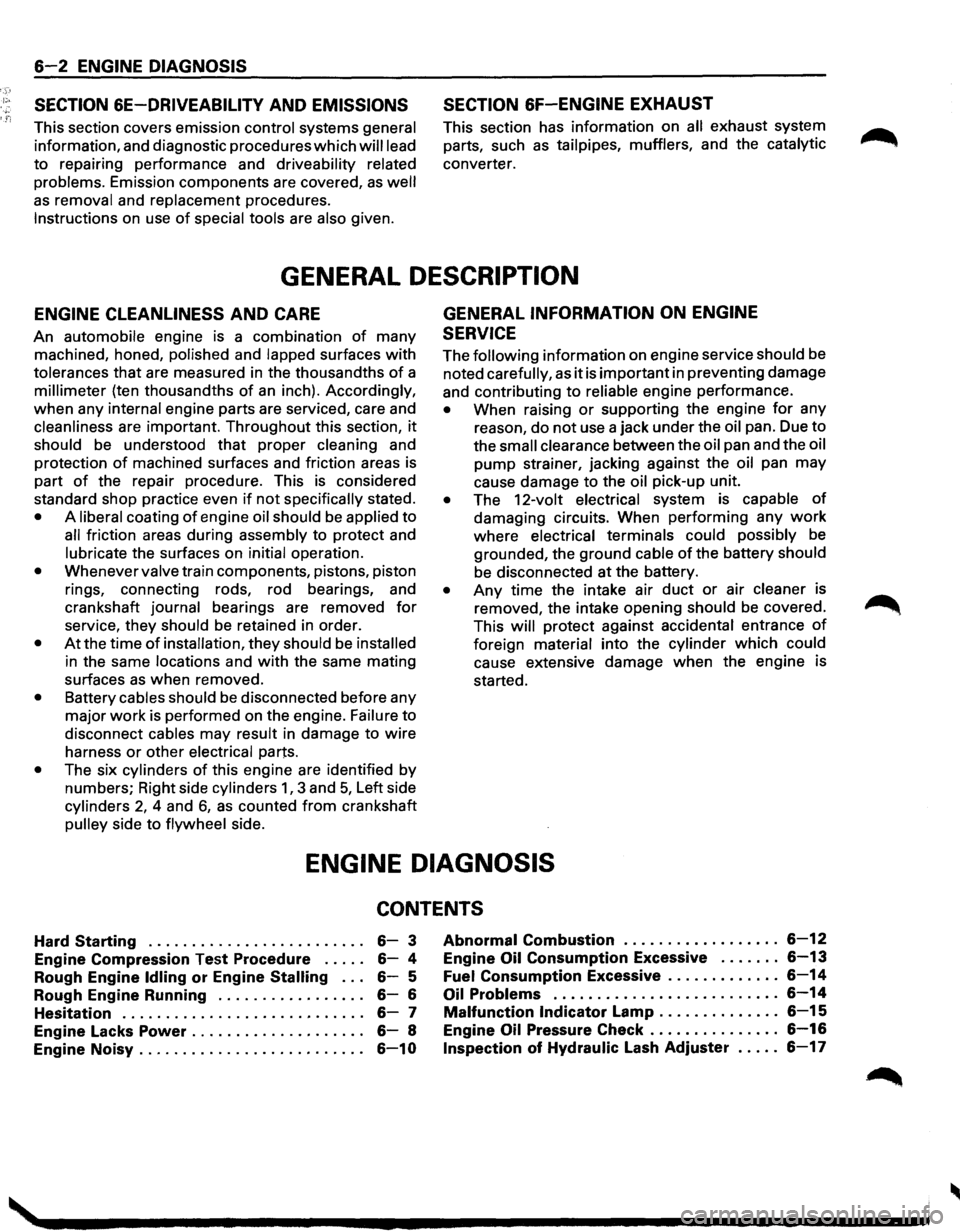
6-2 ENGINE DIAGNOSIS
SECTION 6E-DRIVEABILITY
AND EMISSIONS
This section covers emission control systems general
information, and diagnostic procedures which will lead
to repairing performance and driveability related
problems.
Emission components are covered, as well
as removal and replacement procedures.
Instructions on use
of special tools are also given.
SECTION 6F-ENGINE EXHAUST
This section has information on all exhaust system
parts, such
as tailpipes, mufflers, and the catalytic
converter.
GENERAL DESCRIPTION
ENGINE CLEANLINESS AND CARE
An automobile engine is a combination of many
machined, honed,
polished and lapped surfaces with
tolerances that are measured in the thousandths of a
millimeter (ten thousandths of an inch). Accordingly,
when any
internal engine parts are serviced, care and
cleanliness are important. Throughout this section, it
should be understood that proper cleaning and
protection
of machined surfaces and friction areas is
part
of the repair procedure. This is considered
standard shop practice even
if not specifically stated.
• A liberal coating of engine oil should be applied to
all friction areas during assembly to protect and
lubricate the surfaces on initial operation.
• Whenever valve train components, pistons, piston
rings, connecting rods, rod bearings, and
crankshaft
journal bearings are removed for
service, they should be retained in order.
• At the time of installation, they should be installed
in the same locations and with the same mating
surfaces
as when removed.
• Battery cables should be disconnected before any
major
work is performed on the engine. Failure to
disconnect
cables may result in damage to wire
harness
or other electrical parts.
• The six cylinders of this engine are identified by
numbers; Right side
cylinders 1, 3 and 5, Left side
cylinders 2, 4 and 6, as counted from crankshaft
pulley side to flywheel side.
GENERAL INFORMATION ON ENGINE
SERVICE
The following information on engine service should be
noted
carefully, as it is important in preventing damage
and contributing
to reliable engine performance.
• When raising or supporting the engine for any
reason,
do not use a jack under the oil pan. Due to
the
small clearance between the oil pan and the oil
pump strainer, jacking against the oil pan may
cause damage to the
oil pick-up unit.
• The 12-volt electrical system is capable of
damaging circuits. When performing any work
where electrical terminals could possibly be
grounded, the ground cable of the battery should
be disconnected at the battery.
• Any time the intake air duct or air cleaner is
removed, the intake opening
should be covered.
This
will protect against accidental entrance of
foreign material into the cylinder which could
cause extensive damage when the engine is
started.
ENGINE DIAGNOSIS
CONTENTS
Hard Starting . . . . . . . . . . . . . . . . . . . . . . . . . 6-3
Engine Compression
Test Procedure ..... 6-4
Rough Engine
Idling or Engine Stalling . . . 6-5
Rough Engine Running . . . . . . . . . . . . . . . . .
6-6
Hesitation . . . . . . . . . . . . . . . . . . . . . . . . . . . . 6-7
Engine Lacks
Power . . . . . . . . . . . . . . . . . . . . 6-8
Engine
Noisy .......................... 6-10
Abnormal Combustion . . . . . . . . . . . . . . . . . . 6-12
Engine Oil Consumption Excessive . . . . . . . 6-13
Fuel Consumption Excessive ............. 6-14
Oil Problems . . . . . . . . . . . . . . . . . . . . . . . . . . 6-14
Malfunction Indicator Lamp . . . . . . . . . . . . . . 6-15
Engine Oil Pressure Check ............... 6-16
Inspection of Hydraulic Lash Adjuster . . . . . 6-17