engine ISUZU TROOPER 1995 Workshop Manual
[x] Cancel search | Manufacturer: ISUZU, Model Year: 1995, Model line: TROOPER, Model: ISUZU TROOPER 1995Pages: 1928
Page 1466 of 1928
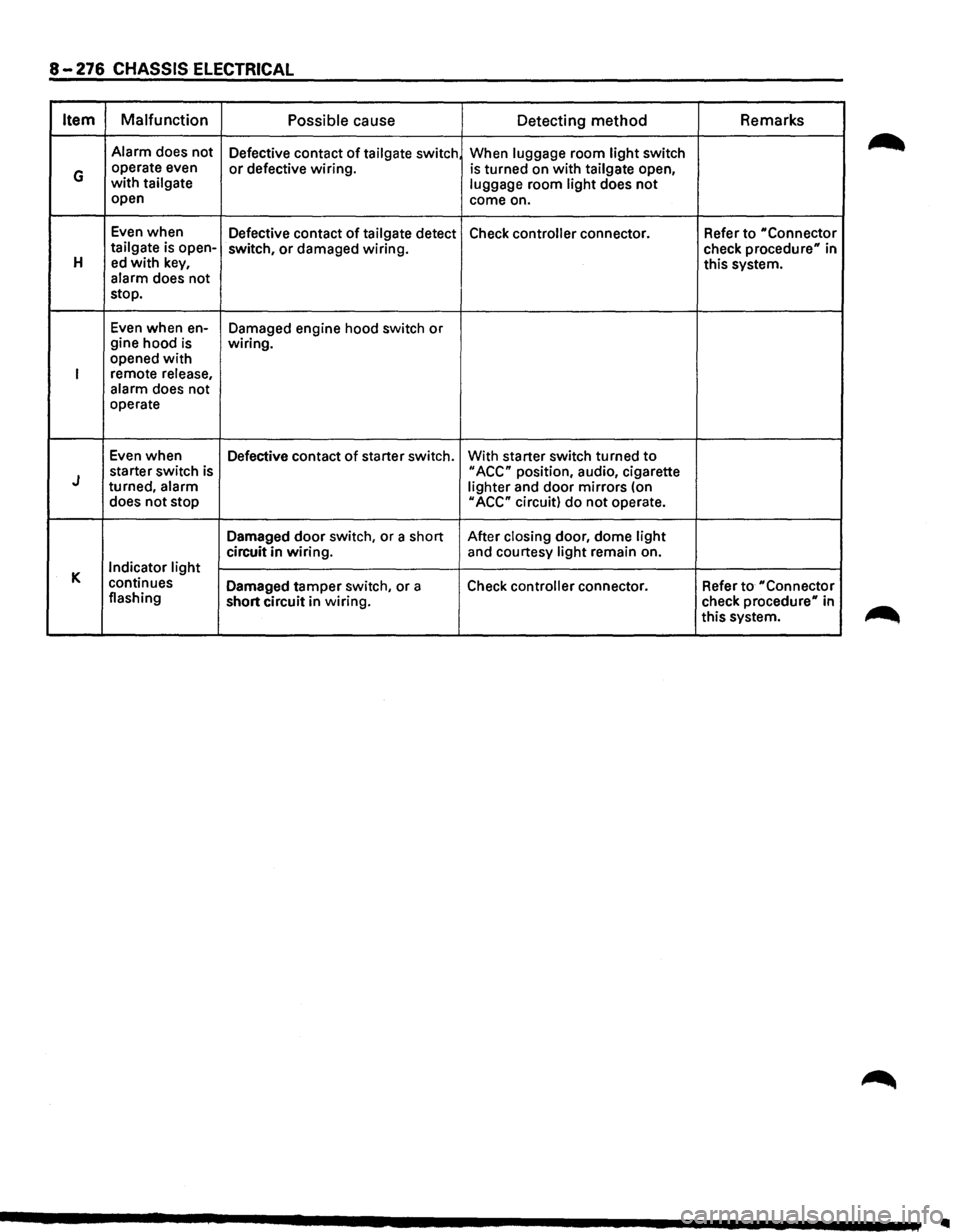
8-276 CHASSIS ELECTRICAL
Item Malfunction
Possible cause
Detecting method Remarks
Alarm
does not
Defective contact of tailgate switch When luggage room light switch
G operate even or defective wiring. is turned on with tailgate open, with tailgate
luggage room light does not open
come on.
Even when
Defective contact
of tailgate detect Check controller connector. Refer to "Connector tailgate is open-
switch, or damaged wiring.
check procedure" in H ed with key, this system.
alarm does not
stop.
Even when en-
Damaged engine hood switch or gine hood is wiring.
opened with
I remote release,
alarm does not
operate
Even when
Defective contact
of starter switch. With starter switch turned to
J starter switch is II ACC" position, audio, cigarette
turned, alarm
lighter and door mirrors (on
does not stop
II ACC" circuit) do not operate.
Damaged
door switch, or a short After closing door, dome light
circuit in wiring. and courtesy light remain on.
K Indicator light
continues Damaged tamper switch, or a
Check controller connector. Refer to "Connector flashing
short circuit in wiring. check
procedure" in
this system.
..
Page 1467 of 1928
------------- -
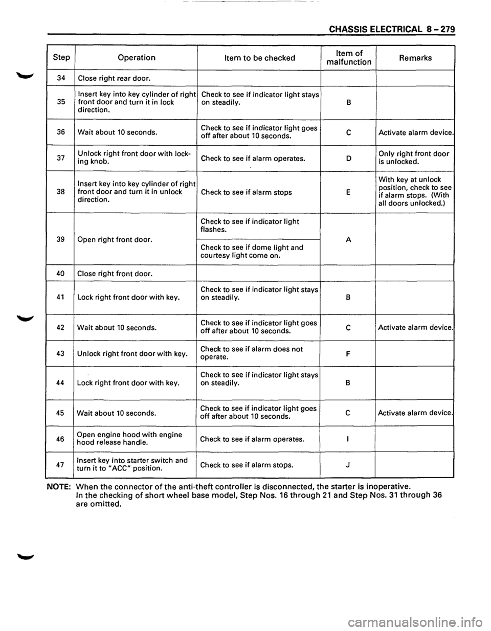
CHASSIS ELECTRICAL 8-279
Step Operation Item to be checked Item of Remarks
malfunction
34 Close right rear door.
Insert key into key cylinder of right
Check to see if indicator light stays 35 front door and turn it in lock on steadily. B direction.
36 Wait about 10 seconds. Check
to see if indicator light goes c Activate alarm device. off after about 10 seconds.
37 Unlock right front door with lock-Check to see if alarm operates. D Only right front door ing knob.
is unlocked.
Insert
key into key cylinder of right With
key at unlock
position, check to see 38 front door and turn it in unlock Check to see if alarm stops E if alarm stops. (With
direction.
all doors unlocked.)
Check to see if indicator light flashes.
39 Open right front door.
A
Check to
see if dome light and
courtesy light come on.
40 Close right front door.
Check to
see if indicator light stays 41 Lock right front door with key.
on steadily. B
42 Wait about 10 seconds. Check
to see if indicator light goes c Activate alarm device. off after about 10 seconds.
43 Unlock right front door with key. Check
to see if alarm does not F operate.
Check to
see if indicator light stays 44 Lock right front door with key.
on steadily. B
45 Wait about 10 seconds. Check
to see if indicator light goes c Activate alarm device. off after about 10 seconds.
46 Open engine hood with engine
Check to see if alarm operates. I hood release handle.
47 Insert key into starter switch and
Check to see if alarm stops. J turn it to "ACC" position.
NOTE: When the connector of the anti-theft controller is disconnected, the starter is inoperative.
In the checking of short wheel base model, Step Nos. 16 through 21 and Step Nos. 31 through 36
are omitted.
Page 1468 of 1928
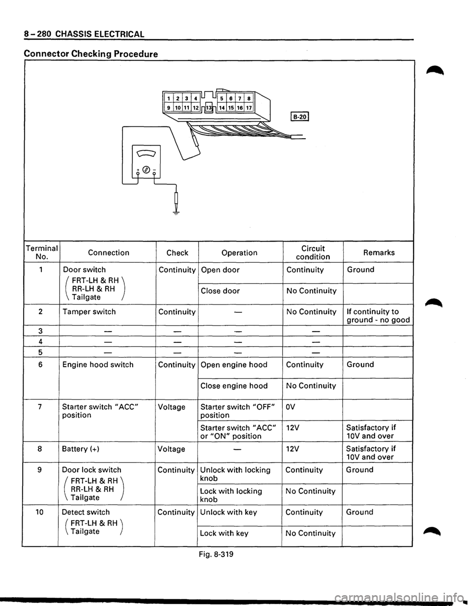
8-280 CHASSIS ELECTRICAL
Connector Checking Procedure
r=-r-,
1I213141Jl..l51al7lsll
9j1ol11!12 rfi114j15j1alnll
I B-2ol "-... ~
~~"'--~~"
c:::::::;
9 °9 L_j L
=
Terminal
Connection Check Operation Circuit
Remarks
No.
condition
1 Door switch Continuity Open door Continuity Ground
( FRT-LH & RH) RR-LH & RH Close door No Continuity Tailgate
2 Tamper switch
Continuity
-No Continuity If continuity to
ground -no good
3 -
-I - -
4 ---
-
5 ----
6 Engine hood switch Continuity Open engine hood Continuity Ground
Close engine hood
No Continuity
7 Starter switch
"ACC" Voltage Starter
switch "OFF" ov
position
position
Starter switch
"ACC" 12V Satisfactory if
or "ON" position 10V and over
8 Battery(+)
Voltage -12V Satisfactory if
10V and over
9 Door lock switch Continuity Unlock with locking Continuity Ground
( FRT-LH & RH) knob
RR-LH & RH Lock with locking No Continuity
Tailgate knob
10 Detect switch Continuity Unlock with key Continuity Ground
(
FRT-LH & RH )
Tailgate Lock
with key No Continuity
Fig. 8-319
..
Page 1469 of 1928
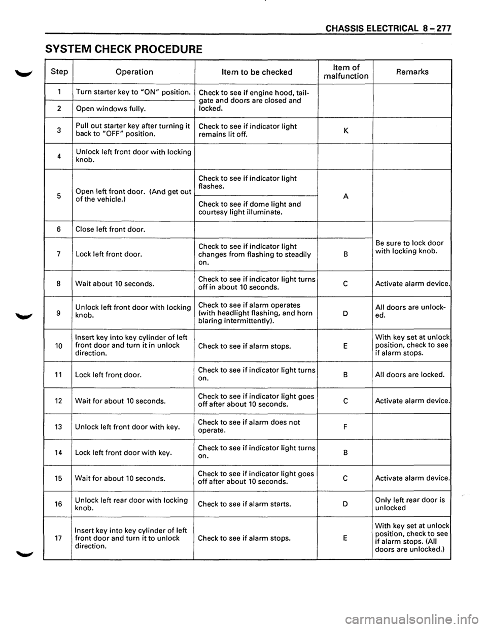
CHASSIS ELECTRICAL 8 ~ 277
SYSTEM CHECK PROCEDURE
Step Operation Item to be checked Item of Remarks malfunction
1
Turn starter key to "ON" position. Check to see if engine hood, tail-
gate and doors are closed and
2
Open windows fully. locked.
3
Pull out starter key after turning it Check to see if indicator light K back to "OFF" position.
remains lit off.
4 Unlock
left
front door with locking
knob.
Check to see if indicator light
Open left front door. (And get out flashes.
5 A
of the vehicle.) Check to see if dome light and
courtesy light illuminate.
6 Close left front door.
Check to see if indicator light Be sure to lock door
7
Lock left front door.
changes from flashing to steadily B with locking knob.
on.
8 Wait about 10 seconds. Check to see if indicator light turns c Activate alarm device. off in about 10 seconds.
Unlock left
front door with locking Check to see if alarm operates All doors are unlock-9 knob. (with
headlight flashing, and horn D ed.
blaring intermittently).
Insert key into key cylinder of left With
key set at unlock
10 front door and turn it in unlock Check to see if alarm stops. E position, check to see
direction. if alarm stops.
11 Lock left front door. Check to see if indicator light turns
B All doors are locked.
on.
12 Wait for about 10 seconds. Check to see if indicator light goes c Activate alarm device. off after about 10 seconds.
13 Unlock left front door with key. Check to see if alarm does not F
operate.
14 Lock left front door with key. Check to see if indicator light turns
B
on.
15 Wait for about 10 seconds. Check to see if indicator light goes c Activate alarm device. off after about 10 seconds.
16 Unlock left rear door with locking Check to see if alarm starts. D Only left rear door is
knob. unlocked
Insert key
into key cylinder of left With
key set at unlock
position, check to see 17 front door and turn it to unlock Check to see if alarm stops. E if alarm stops. (All direction.
doors are unlocked.)
Page 1472 of 1928
8-282 CHASSIS ELECTRICAL
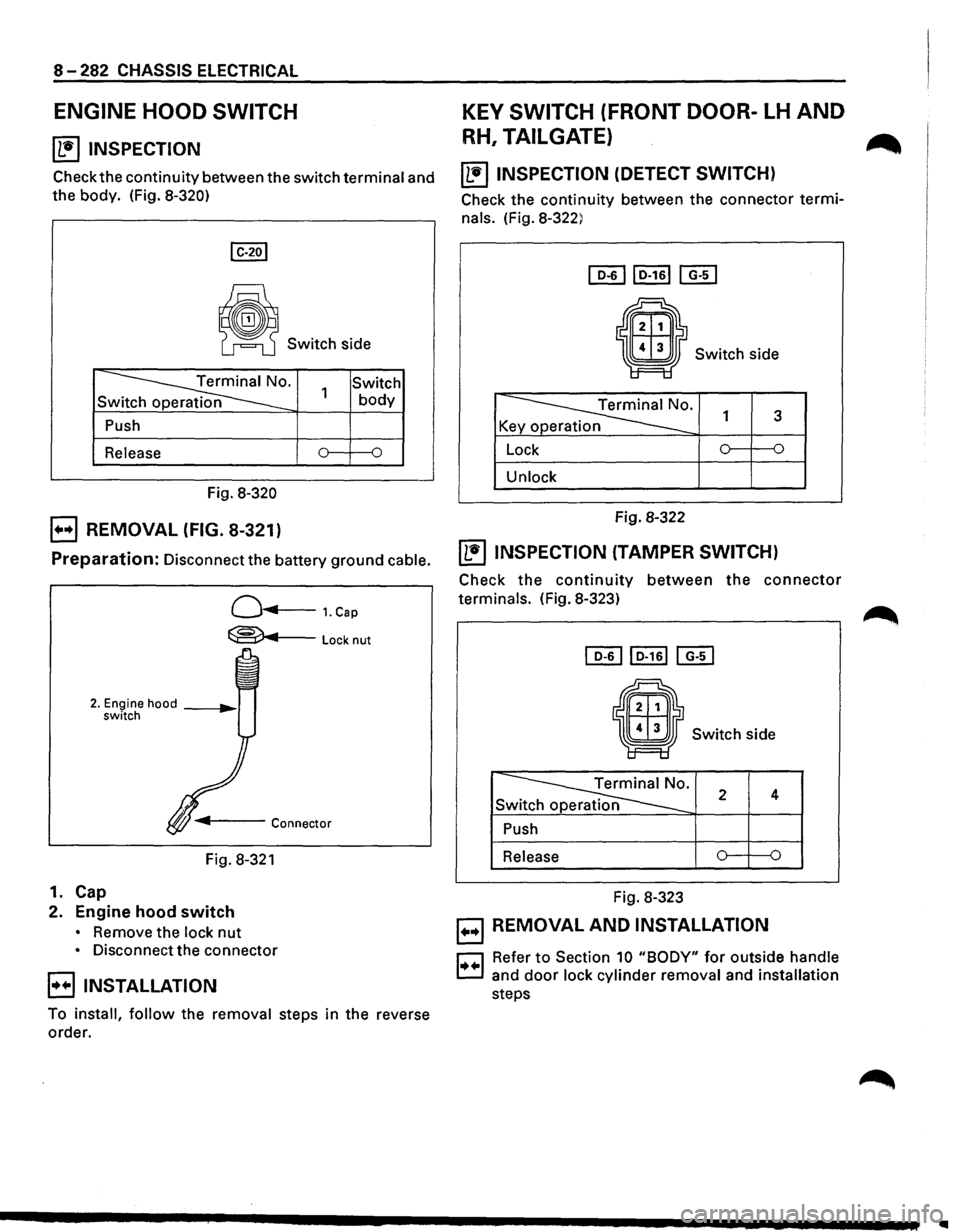
ENGINE HOOD SWITCH
~ INSPECTION
Check the continuity between the switch terminal and
the body. (Fig. 8-320)
~ Switch side
~· Sw
Push
Release
Fig.
8-320
E) REMOVAL (FIG. 8-321)
Switch 1 body
Preparation: Disconnect the battery ground cable.
Q...,..,...___ 1. Cap
~Locknut
Fig. 8-321
1. Cap
2. Engine hood switch
• Remove the lock nut
• Disconnect the connector
B INSTALLATION
To install, follow the removal steps in the reverse
order.
KEY SWITCH (FRONT DOOR-LH AND
RH, TAILGATE) ...
~ INSPECTION (DETECT SWITCH)
Check the continuity between the connector termi
nals. (Fig. 8-322)
Switch side
~· K y p 1 3
Lock 0 {)
Unlock
Fig. 8-322
~ INSPECTION (TAMPER SWITCH)
Check the continuity between the connector
terminals. (Fig. 8-323)
• Switch side
~· Sw 2 4
Push
Release
Fig. 8-323
B REMOVAL AND INSTALLATION
r::J Refer to Section 10 "BODY" for outside handle
c:.:J and door lock cylinder removal and installation
steps
Page 1478 of 1928
8-288 CHASSIS ELECTRICAL
METER AND WARNING/INDICATOR LIGHT
GENERAL DESCRIPTION
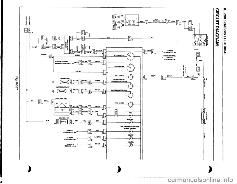
The circuit consists of the starter switch, meter assembly, vehicle speed sensor, clutch switch, transmission
switch, lighting switch,
turn signal switch, thermo unit, oil pressure unit, Engine Control Module, fuel tank unit,
4WD
SW, oil pressure switch, parking brake switch, brake fluid switch, seat belt switch and illumination
controller.
The meter ASM contains the speedometer, tachometer, voltmeter, engine coolant temperature gauge, oil
pressure gauge, fuel gauge and warning/indicator lights.
The meter warning/indicator lights and
their bulb sockets are a unit, they are installed from the back of the
speedometer assembly.
Page 1480 of 1928
•
, ce· CX) I w w .....
..
~ m
0
z
0 0 <
m
n
"'
-1
:D
"'
:z:
= ~~ :;; )
O.SIItll 2B
O.&B
ID
-,~
r
-•3
'
.. '
'
' ' IGNITION
CONTROL
MODULECTO
PAGE
S.S1,
531
ECMCASI
(TO PAGE
11-51,
531
TCMihl (TO PAGE
8-1t41
TCMIA111 (TO PAGE
11-1141
~[~} m[i] ~ .:. II
. 0 j[~}l
I'lL,
II"
:----~
.. :~.:,._
:
fill
:~
~~~~ I -··
.!., -
SPEEOOMETER TACHOMETER VOLTMETER ENGINE
COOLANT
TEMPERATURE
GAUGE
OIL PRESSUSRE
GAUGE
FUEL
GAUGE MALFUNCT10N
INDICATOR
lCHECKENGWEI
POWEll -TER
)
O.SL
ECMIDIII
ITO PAGE
11-51,
531
CRUISE
CONTROL UNITI131 ITO PAGE
11-1741
O.SLJY ;;
~ ~ '!' ;;: ~ ~ n ~ ~ )
n -:JJ n c =i c -)> G) :JJ )> 3:
co I N CD 0 (") :.t: > Cl) Cl) Cl) m ,.... m Q , n )> ,....
Page 1484 of 1928
8-294 CHASSIS ELECTRICAL
DIAGNOSIS
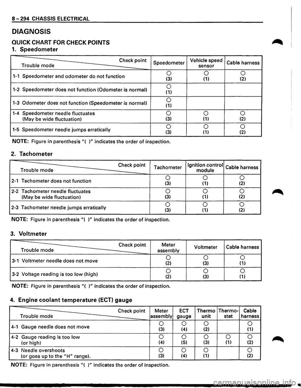
QUICK CHART FOR CHECK POINTS
1. Speedometer
Trouble mode Check
point
1-1 Speedometer
and odometer do not function
1-2 Speedometer does not function (Odometer is normal)
1-3 Odometer does not function (Speedometer is normal)
1-4 Speedometer needle fluctuates
(May be wide fluctuation)
1-5 Speedometer
needle jumps erratically Speedometer
0 (3)
0 (1)
0 (1)
0 (3)
0 (3)
NOTE: Figure
in parenthesis "( )" indicates the order of inspection.
2. Tachometer
Check point Tachometer Trouble mode
2-1 Tachometer does not function 0 (3)
2-2 Tachometer needle fluctuates 0
(May be wide fluctuation) (3)
2-3 Tachometer needle jumps erratically 0 (3)
NOTE: Figure in parenthesis "( )" indicates the order of inspection.
3. Voltmeter
Check point Meter
Trouble mode
assembly
3-1 Voltmeter needle does not move 0 (2)
3-2 Voltage reading is too low (high) 0 (2)
NOTE: Figure in parenthesis "( )" indicates the order of inspection.
4. Engine coolant temperature (ECT) gauge
Vehicle speed
Cable harness
sensor
0 0 (1) (2)
0
0 (1) (2)
0 0 (1) (2)
Ignition control
Cable harness
module
0 0
(1) (2)
0 0 (1) {2)
0 0 (1) (2)
Voltmeter Cable
harness
0 0 (3) (1)
0
0 (3) (1)
Check point Meter ECT Thermo Thermo-Cable
Trouble mode
assembly gauge unit stat harness
4-1 Gauge needle does not move 0
0 0
0
(3) (4) (2) (1)
4-2 Gauge reading is too low 0 0 0 0 0
(or high) (4) (5) (3) (1) (2)
4-3 Needle overshoots 0 0 0 0
(or goes up to the "H" range). (3) (4) (1) (2)
NOTE: Figure in parenthesis "( )" indicates the order of inspection.
..
Page 1485 of 1928
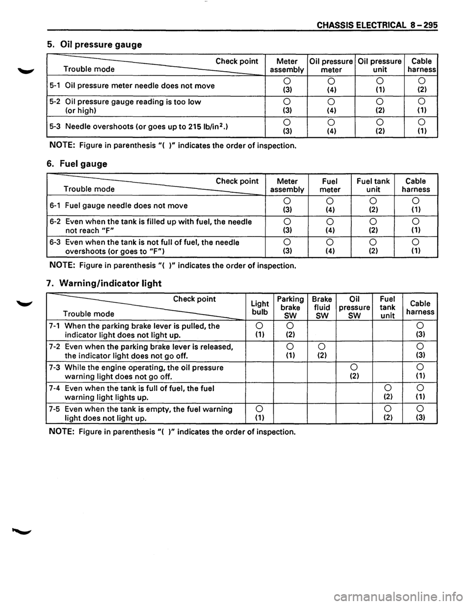
CHASSIS ELECTRICAL 8-295
5. Oil pressure gauge
Check point Meter Oil pressure Oil pressure Cable
Trouble mode
assembly meter unit harness
5-1 Oil pressure meter needle does not move 0
0 0
0 (3) (4) (1) (2)
5-2 Oil pressure
gauge reading is too low 0
0 0
0
(or
high) (3) (4) (2) (1)
5-3 Needle overshoots
(or goes up to 2151b/in2.) 0
0 0 0 (3) (4) (2)
(1)
NOTE: Figure
in parenthesis "( )" indicates the order of inspection.
6. Fuel gauge
Check point Meter Fuel Fuel tank Cable
Trouble mode assembly
meter unit harness
6-1 Fuel gauge needle does not move 0
0 0 0 (3) (4) (2) (1)
6-2 Even when the tank is filled up with fuel, the needle 0
0 0
0
not reach "F" (3) (4) (2)
(1)
6-3
Even when the tank is not full of fuel, the needle 0
0 0
0
overshoots (or goes to "F") (3) (4) (2) (1)
NOTE: Figure
in parenthesis "( )" indicates the order of inspection.
7. Warning/indicator light
~
Light Parking
Brake Oil Fuel Cable brake fluid pressure tank bulb sw sw sw unit harness
e
7-1 When the parking brake lever is pulled, the 0 0 0
indicator light does not light up. (1) (2) (3)
7-2 Even
when the parking brake lever is released, 0 0 0
the indicator light does not go off. (1) (2) (3)
7-3 While the engine operating,
the oil pressure 0 0
warning light does not go
off. (2)
(1)
7-4 Even
when the tank is full of fuel, the fuel 0 0
warning light lights
up. (2) (1)
7-5 Even
when the tank is empty, the fuel warning 0 0
0
light does not light up. (1) (2)
(3)
NOTE: Figure in parenthesis "( )" indicates the order of inspection.
Page 1490 of 1928
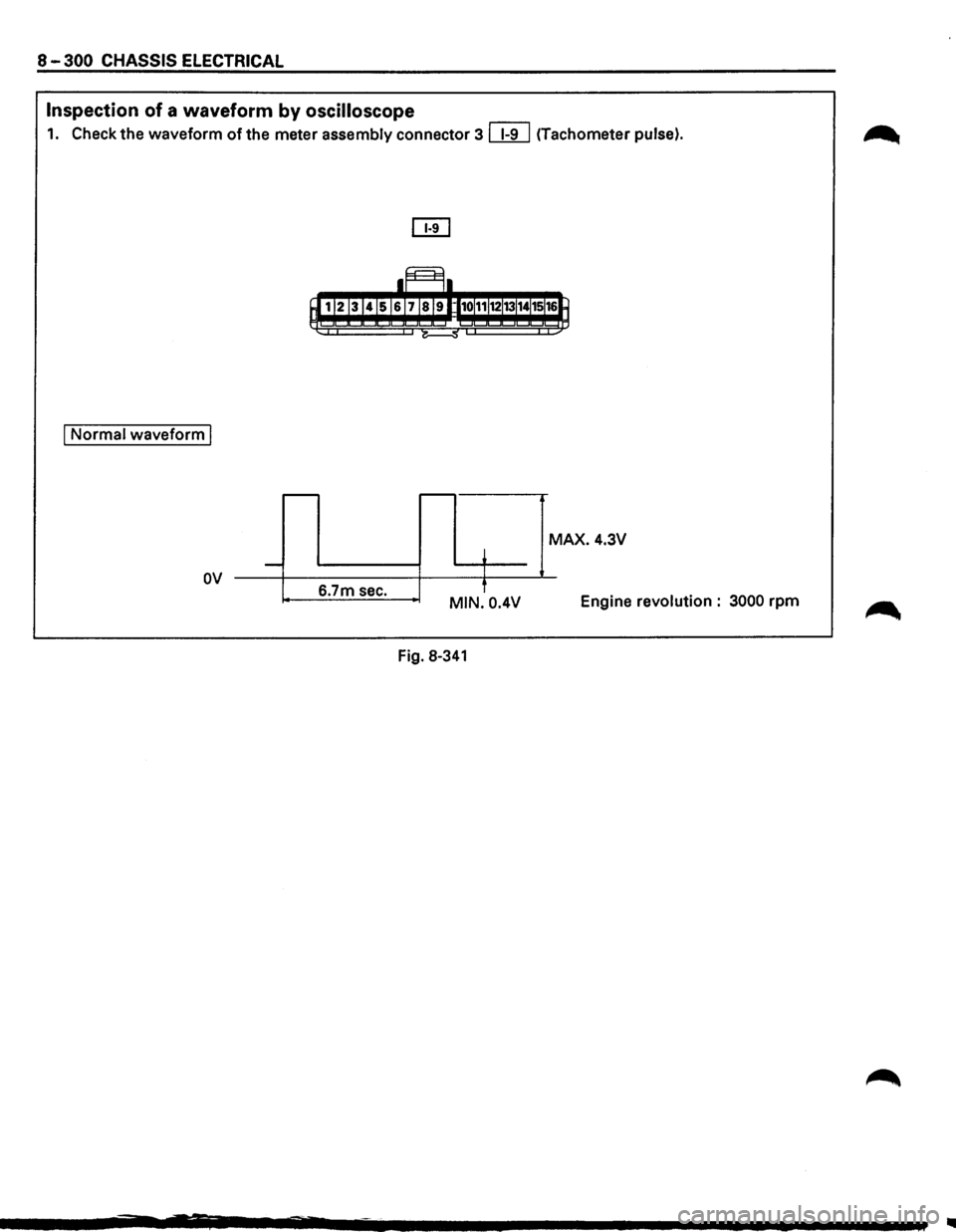
8-300 CHASSIS ELECTRICAL
Inspection of a waveform by oscilloscope
1. Check the waveform of the meter assembly connector 3 ~ (Tachometer pulse).
I Normal waveform I
....---r---
MAX. 4.3V
~ -
MIN. 0.4V Engine revolution: 3000 rpm
I
6.7m sec.
'
ov
Fig. 8-341
..