engine ISUZU TROOPER 1995 Workshop Manual
[x] Cancel search | Manufacturer: ISUZU, Model Year: 1995, Model line: TROOPER, Model: ISUZU TROOPER 1995Pages: 1928
Page 1149 of 1928
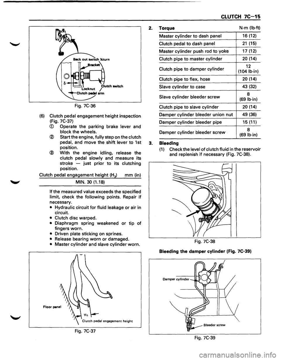
Fig. 7C-36
(6) Clutch pedal engagement height inspection
(Fig.
7C-37)
® Start the engine, fully step on the clutch
pedal,
and move the shift lever to 1st
position.
@ With the engine idling, release the
clutch pedal slowly and measure its
stroke -just prior
to its clutching
position.
Clutch pedal engagement height (H3) mm (in)
MIN. 30 (1.18)
If the
measured value exceeds the specified
limit, check the following points. Repair if
necessary.
• Hydraulic circuit for fluid leakage or air in
circuit.
• Clutch disc warped.
• Diaphragm spring weakened or tip of
fingers worn.
• Driven plate sticking on sprines.
• Release bearing worn or damaged.
• Master cylinder and slave cylinder worn.
Floor panel
Fig. 7C-37
CLUTCH 7C-15
2. Torque N·m (lb·ft)
Master cylinder to dash panel 16 (12)
Clutch pedal to dash panel 21 (15)
Master cylinder push rod to yoke 17 (12)
Clutch pipe to master cylinder 20 (14)
Clutch pipe
to damper cylinder 12
(104 lb·in)
Clutch
pipe to flex, hose 20 (14)
Slave cylinder to case 43 (32)
Slave
cylinder bleeder screw 8 (691b·in)
Clutch
pipe to slave cylinder 20 (14)
Damper cylinder bleeder union nut 49 (36)
Damper cylinder bleeder pipe 15 (11)
Damper cylinder
bleeder screw 8 (69 lb·in)
3. Bleeding
(1) Check
the level of clutch fluid in the reservoir
and
replenish if necessary (Fig. 7C-38).
Fig. 7C-38
Bleeding the damper cylinder (Fig. 7C-39)
Damper cylinder
Fig. 7C-39
Page 1155 of 1928
CLUTCH 7C-21
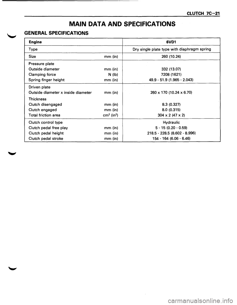
MAIN DATA AND SPECIFICATIONS
GENERAL SPECIFICATIONS
Engine 6VD1
Type Dry single plate type with diaphragm spring
Size mm (in) 260 (10.24)
Pressure plate
Outside
diameter mm (in) 332 (13.07)
Clamping force N (lb) 7208 (1621)
Spring finger height mm (in) 49.9 -51.9 (1.965 -2.043)
Driven plate
Outside
diameter x inside diameter mm (in) 260 X 170 (10.24 X 6.70)
Thickness
Clutch disengaged mm (in) 8.3 (0.327)
Clutch engaged mm (in) 8.0 (0.315)
Total friction area cm2 (in2
) 304 X 2 (47 X 2)
Clutch control type Hydraulic
Clutch pedal
free play mm (in) 5 -15 (0.20 -0.59)
Clutch pedal height mm (in) 218.5 -228.5 (8.602 -8.996)
Clutch pedal stroke mm (in) 154 -164 (6.06 -6.46)
Page 1161 of 1928
TRANSFER CASE 70-3
ON-VEHICLE SERVICE
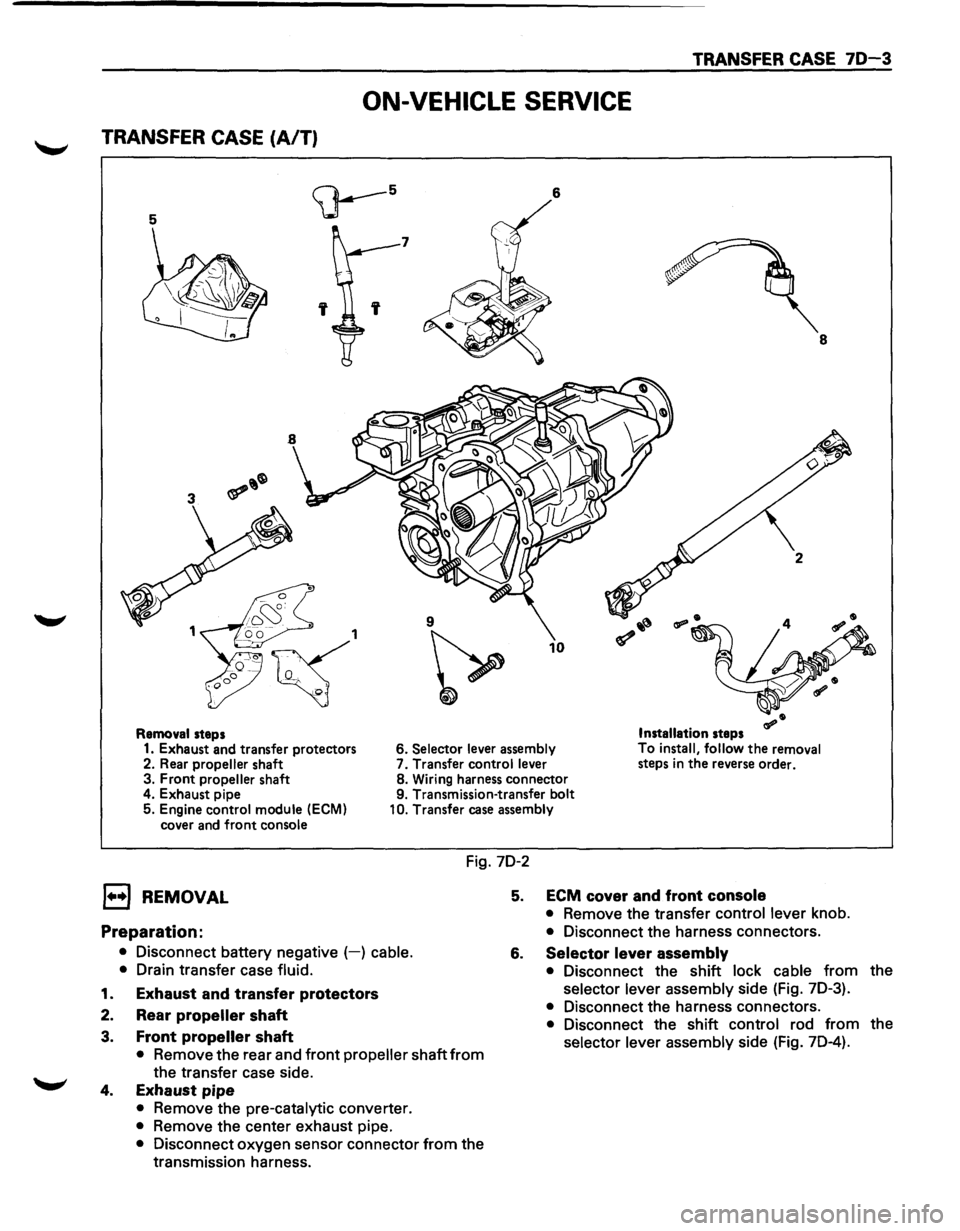
TRANSFER CASE (A/T)
5
<;J---5 6
7
' 8
9
~
10
Removal steps Installation steps
1. Exhaust and transfer protectors 6. Selector lever
assembly To
install, follow the removal
steps in the reverse order.
2. Rear propeller shaft 7.
Transfer control lever
3. Front propeller shaft 8.
Wiring harness connector
4. Exhaust pipe 9. Transmission-transfer bolt
5. Engine control module
(ECM)
cover and front console 10.
Transfer case assembly
Fig. 7D-2
l••l REMOVAL
Preparation:
• Disconnect battery negative (-) cable.
•
Drain transfer case fluid.
1. Exhaust and transfer protectors
2. Rear propeller shaft
3. Front propeller shaft
• Remove the rear and front propeller shaft from
the transfer case side.
4. Exhaust pipe
• Remove the pre-catalytic converter.
• Remove the center exhaust pipe.
• Disconnect oxygen sensor connector from the
transmission harness.
5. ECM cover and front console
• Remove the transfer control lever knob.
• Disconnect the harness connectors.
6. Selector lever assembly
• Disconnect the shift lock cable from the
selector lever assembly side (Fig. 7D-3).
• Disconnect the harness connectors.
• Disconnect the shift control rod from the
selector lever assembly side (Fig. 7D-4).
Page 1164 of 1928
70-6 TRANSFER CASE
EJ REMOVAL
1. Rear propeller shaft
• Disconnect the rear propeller shaft from the
transfer case side.
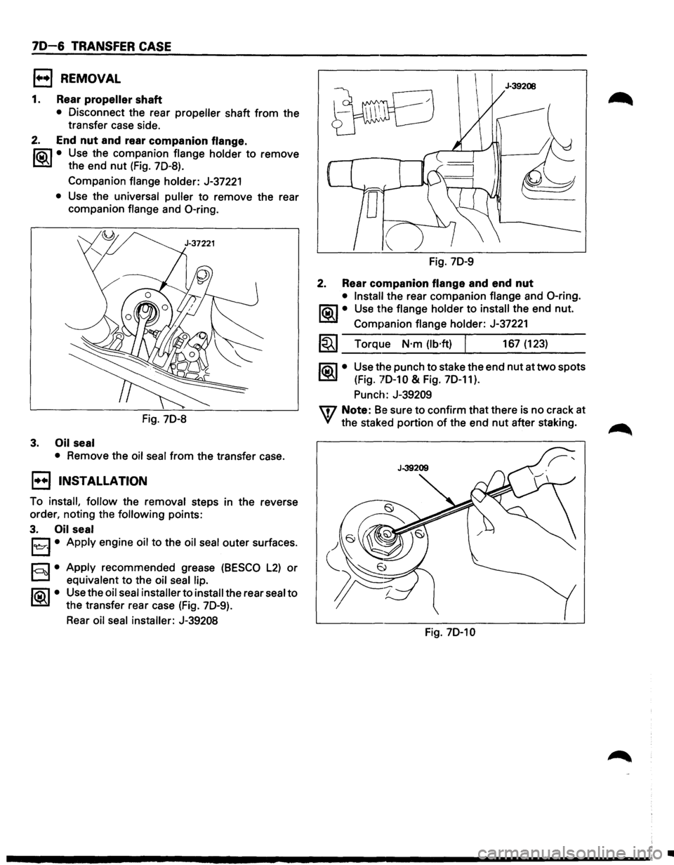
2. End nut and rear companion flange.
li5\l • Use the companion flange holder to remove
~ the end nut (Fig. 70-8).
Companion flange holder: J-37221
• Use the universal puller to remove the rear
companion flange and 0-ring.
Fig. 70-8
3. Oil seal
•
Remove the oil seal from the transfer case.
1••1 INSTALLATION
To install, follow the removal steps in the reverse
order, noting the
following points:
3. Oil seal
l
D equivalent to the oil seal lip.
li5\l • Use the oil seal installer to install the rear seal to
~ the transfer rear case (Fig. 70-9).
Rear oil seal installer: J-39208
Fig. 70-9
2. Rear companion flange and end nut
• Install the rear companion flange and 0-ring.
l<9l..l• Use the flange holder to install the end nut.
Companion flange holder:
J-37221
1~1 Torque N·m (lb·ft) I 167 (123)
~·
Use the punch to stake the end nut at two spots
(Fig.
70-10 & Fig. 70-11).
Punch: J-39209
m Note: Be sure to confirm that there is no crack at
VI the staked portion of the end nut after staking.
Fig. 70-10
•
Page 1170 of 1928

70-12 TRANSFER CASE
5. Speedometer drive gear
6. Ball
7. Collar
8. Bearing snap ring
• Use a pair of snap ring pliers to remove the
snap ring.
9. Ball bearing
10. Rear output shaft
l'iC\1 • Use a bench press and the bearing remover to
~ remove the ball bearing (Fig. 70-24).
Bearing remover: J-22912-01
11. Transfer rear case (with oil seal)
Fig. 70-24
Wtl INSPECTION AND REPAIR
Refer to "TRANSFER CASE ASSEMBLY" in this Section
for inspection and repair.
l•!•l REASSEMBLY
11. Transfer rear case (with oil seal)
Oil seal
replacement
• Remove the oil seal from the transfer rear case.
D • Apply engine oil to the oil seal outer surfaces. 12::::]
§1•
~·
Fill in recommended grease (BESCO L2) or
equivalent in the oil seal lip.
Use the oil seal installer to install the rear oil
seal
to the transfer rear case (Fig. 70-25).
Oil
seal installer: J-39208
Fig. 70-25
10.
Rear output shaft
9. Ball bearing
l'iC\1 • Use the ball bearing installer and the adapter to
~ instalil the ball bearing (Fig. 70-26).
Ball
bearing installer: J-37223
Adap1ter: J-37486
Fig. 70-26
8. Bearing snap ring
7. Collar
6. Ball
J.37486
5. Speedometer drive gear (Fig. 70-27)
4. Ball bearing
liC\1 • Use the ball bearing installer to install the ball
~ bearing (Fig. 70-28).
Ball
be1aring installer: J-37223
•
Page 1181 of 1928
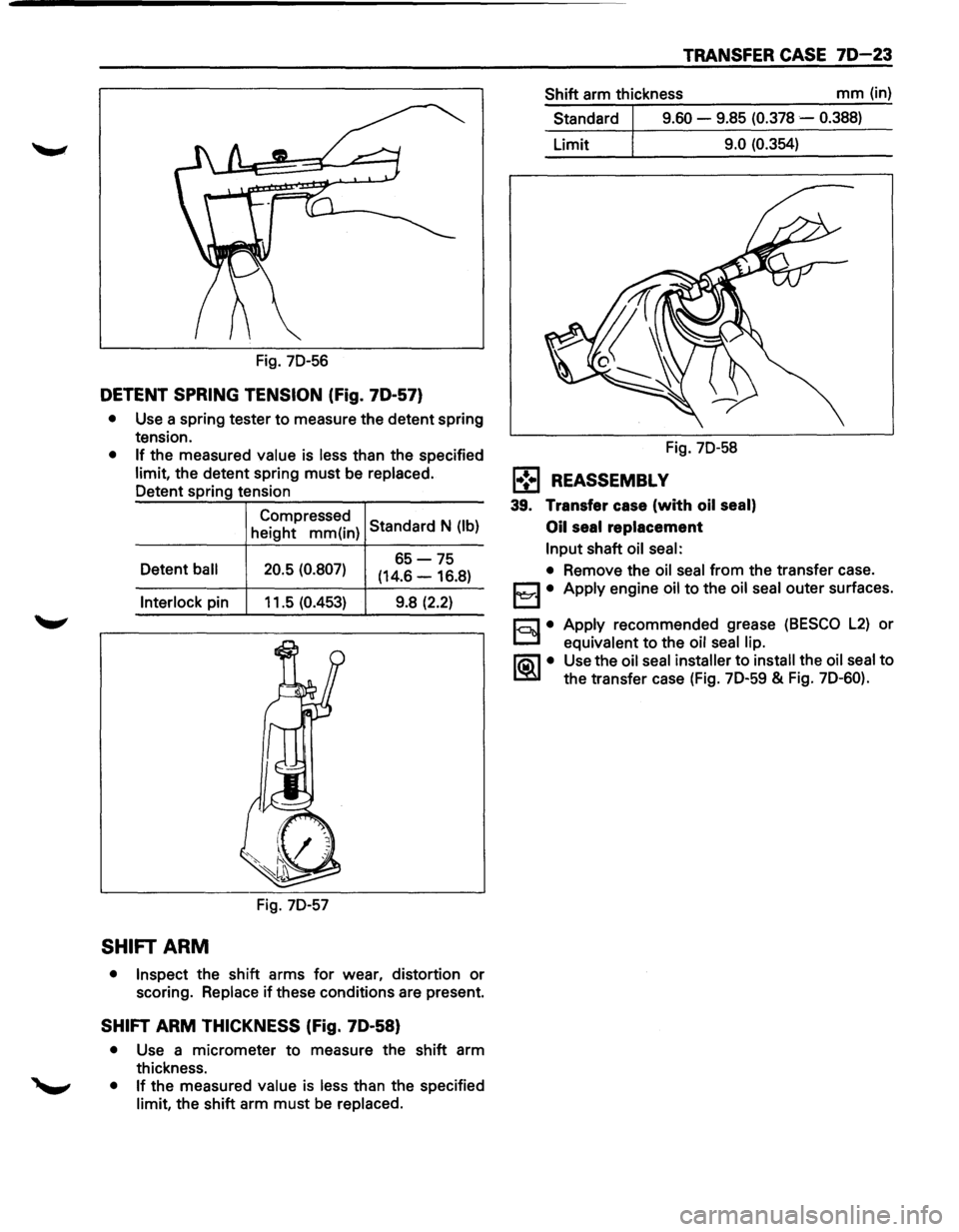
Fig. 7D-56
DETENT SPRING TENSION (Fig. 70-57)
• Use a spring tester to measure the detent spring
tension.
• If the measured value is less than the specified
limit, the detent spring must be replaced.
Detent spring tension
Compressed Standard N (lb)
height mm(in)
Detent
ball 20.5 (0.807) 65-75
(14.6 -16.8)
Interlock pin 11.5 (0.453) 9.8 (2.2)
Fig. 7D-57
SHIFT ARM
•
Inspect the shift arms for wear, distortion or
scoring. Replace
if these conditions are present.
SHIFT ARM THICKNESS (Fig. 70-58)
• Use a micrometer to measure the shift arm
thickness.
• If the measured value is less than the specified
limit, the shift arm must be replaced.
TRANSFER CASE 70-23
Shift arm thickness mm (in)
Standard
9.60 - 9.85 (0.378 -0.388)
Limit 9.0 (0.354)
Fig. 7D-58
l•!•l REASSEMBL V
39. Transfer case (with oil seal)
Oil
seal replacement
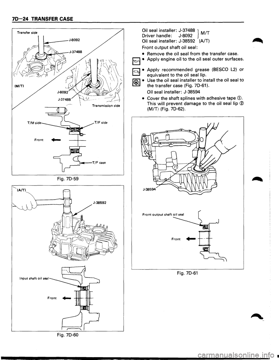
Input shaft oil seal:
• Remove the oil seal from the transfer case.
j3 • Apply engine oil to the oil seal outer surfaces.
r.:;::'l • Apply recommended grease (BESCO L2) or
D equivalent to the oil seal lip.
li:\1 • Use the oil seal installer to install the oil seal to
~ the transfer case (Fig. 7D-59 & Fig. 7D-60).
Page 1182 of 1928
70-24 TRANSFER CASE
Transfer side
(M/TI
--...___ (A/TI
T/M side
Front
Input shaft oil seal
Fig. 70-59
Fig. 70-60
lc::: I \f~ /(\A\~
t \l(
~~~
-------'"'-~'~
Transmission side
T/F side
Oil seal installer: J-37488 } MIT
Driver handle: J-8092
Oil
seal installer: J-38592 (AIT)
Front
output shaft oil seal:
• Remove the oil seal from the transfer case.
j
~·
Apply recommended grease (BESCO L2) or
equivalent to the oil seal lip.
Use the oil seal
installer to install the oil seal to
the transfer case (Fig.
70-61 ).
Oil sHal installer: J-38594
• Cover the shaft splines with adhesive tape CD.
This will prevent damage to the oil seal lip ®
(MIT) (Fig. 70-62).
Fig. 70-61
•
Page 1184 of 1928
70-26 TRANSFER CASE
Fig. 70-66
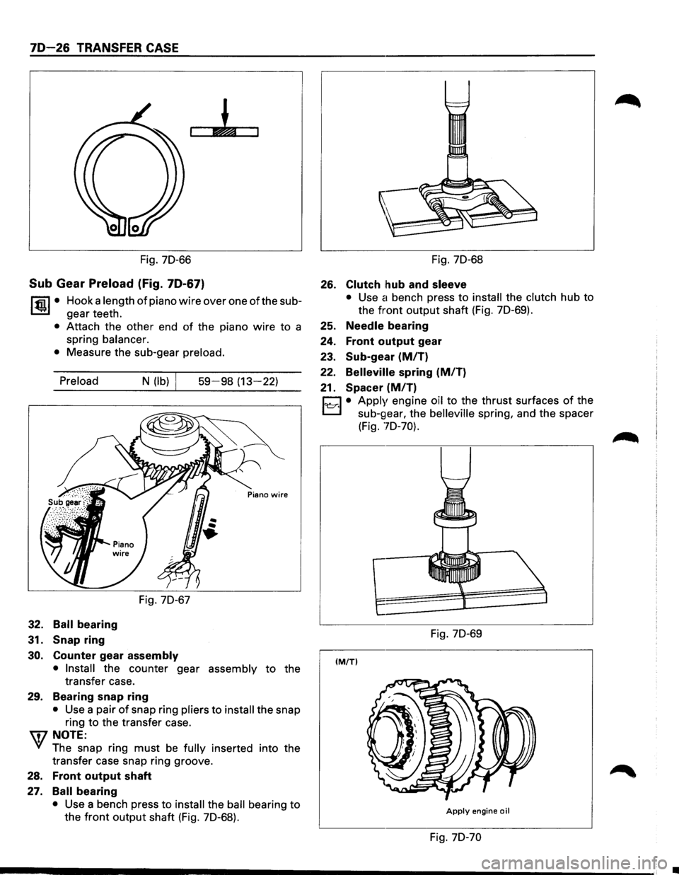
Sub Gear Preload (Fig. 70-67)
~·
Hook a length of piano wire over one of the sub
gear teeth.
• Attach the other end of the piano wire to a
spring
balancer.
•
Measure the sub-gear preload.
Preload
32. Ball bearing
31.
Snap ring
N (lb)
Fig. 70-67
30. Counter gear assembly
59-98 (13-22)
• Install the counter gear assembly to the
transfer case.
29. Bearing snap ring
• Use a pair of snap ring pliers to install the snap
ring
to the transfer case.
W NOTE:
~ The snap ring must be fully inserted into the
transfer case snap ring groove.
28. Front output shaft
27. Ball bearing
• Use a bench press to install the ball bearing to
the front output shaft (Fig. 70-68).
Fig. 70-68
26. Clutch hub and sleeve
• Use a bench press to install the clutch hub to
the front output shaft (Fig. 70-69).
25. Needle bearing
24.
Front output gear
23. Sub-gear
(MIT)
22. Belleville spring (MIT)
21. Spacer (M/T)
C1 • Apply engine oil to the thrust surfaces of the
t.::::::J sub-gear, the belleville spring, and the spacer
(Fig.
70-70).
Fig. 70-69
(M/TI
Apply engine oil
Fig. 70-70
•
Page 1187 of 1928
TRANSFER CASE 70-29
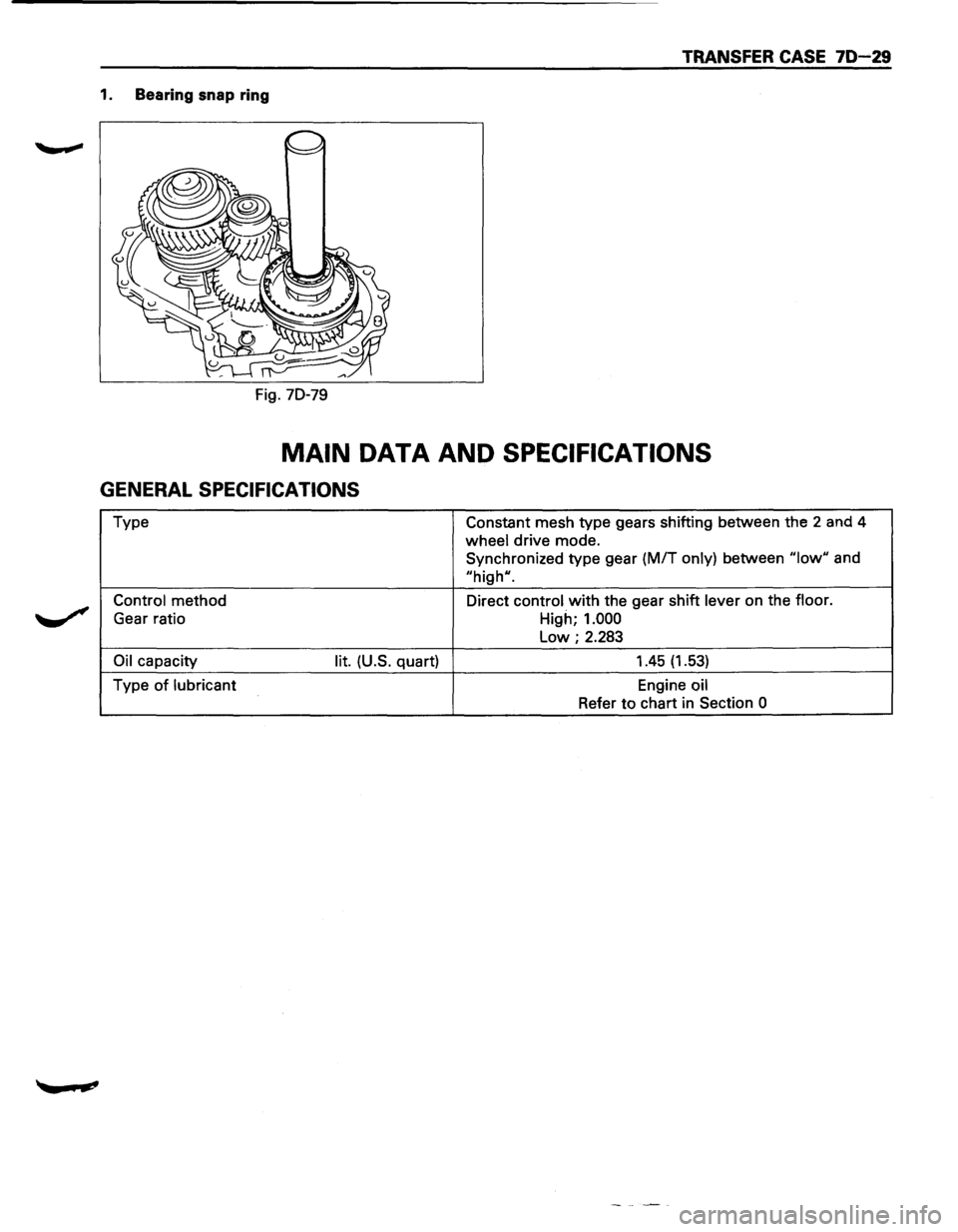
1. Bearing snap ring
Fig. 70-79
MAIN DATA AND SPECIFICATIONS
GENERAL SPECIFICATIONS
Type Constant mesh type gears shifting between the 2 and 4
wheel drive mode.
Synchronized type gear
(M/T only) between "low" and
"high".
Control method Direct control with the gear shift lever on the floor.
Gear ratio
High; 1.000
Low; 2.283
Oil capacity lit. (U.S. quart) 1.45 (1.53)
Type of lubricant Engine oil
Refer to chart in Section
0
Page 1191 of 1928

CHASSIS ELECTRICAL 8-1
·SECTION 8
CHASSIS ELECTRICAL
'\f CAUTION: .
When fasteners are removed, always reinstall them at the same location from which they were removed.
If a fastener needs to be replaced, use the correct part number fastener for that application. If the correct
part number fastener is not
available, a fastener of equal size and strength (or stronger) may be used.
Fasteners that are not reused, and those requiring thread
locking compound, will be called out. The correct
torque
values must be used when installing fasteners that require it. If the above conditions are not
followed, parts or system damage could result.
CONTENTS
General Information .................................... 8-2
Notes for Working on Electrical
Items .................................................... 8-2
Symbols and Abbreviations ................. 8-8
Symbols ............................................ 8-8
Abbreviations ................................... 8-9
Parts for Electrical Circuit ..................... 8-10
Wiring ............................................... 8-10
Fuse .................................................. 8-11
Fusible Link ....................................... 8-12
Circuit Breaker ................................... 8-12
Relay ................................................. 8-12
Relay Specifications and
Configurations ................................ 8-13
Diode ................................................. 8-14
Connector ......................................... 8-15
Reading the Circuit Diagram ................ 8-17
Main Data and Specifications .................... 8-19
Bulb Specifications ................................ 8-19
Fuse,
Fusible Link and
Circuit Breaker Location ..................... 8-21
Fuse
Block Circuit .................................. 8-22
Reference Table of Fuse, Fusible
Link and Circuit Breaker ..................... 8-23
Relay Location ....................................... 8-27
Diode Location .......................................
8-28
Grounding Point .................................... 8-29
Reference Table ................................ 8-29
Location ............................................ 8-31
Cable Harness Routing .......................... 8-34
System Repair .............................................. 8-38
Start and Charging ................................ 8-38
Engine Control Module
(ECM) ................................................... 8-47
Headlight and Fog Light ........................ 8-58
Front Side Marker Light, Parking Light,
Taillight, License Plate Light and
Illumination Light .............................. 8-76
Stoplight and Rear Defogger .............. 8-92
Turn Signal Light, Hazard
Warning
Light, Cornering Light,
Backup
Light and Horn ..................... 8-106
Dome Light, Luggage room Light,
Courtesy Light, Map Light,
Seat Belt Switch and
Warning Buzzer ................................. 8-128
Power Door Lock ................................. 8-142
Power
Window .................................... 8-156
Cruise
Control ...................................... 8-172
Anti-Lock Brake
System (ABS) ........... 8-178
Rear
Wheel Anti-Lock Brake
System (RWAL) ................................. 8-185
Transmission
Control Module
(TCM) ................................................. 8-192
A/T Shift Lock ...................................... 8-200
Windshield
Wiper/Washer and
Rear
Wiper/Washer .......................... 8-205
Headlight wiper /washer ..................... 8-232
Audio, Auto Antenna,
Cigarette
Lighter and digital clock ... 8-246
Power Door Mirror ............................... 8-254
Anti-theft System ................................ 8-270
Meter and Warning/Indicator Light ... 8-288
A/T Shift Indicator ............................... 8-336
Heater and
Air Conditioning ............... 8-340
Sun
Roof ............................................... 8-346
Power Seat ........................................... 8-360
Seat
Heater .......................................... 8-37 4
Supplemental Restraint
System (SRS) -AIR BAG ................... 8-382