engine ISUZU TROOPER 1995 Workshop Manual
[x] Cancel search | Manufacturer: ISUZU, Model Year: 1995, Model line: TROOPER, Model: ISUZU TROOPER 1995Pages: 1928
Page 1246 of 1928
8-56 CHASSIS ElECTRICAl
STARTER SWITCH NOTE:
Refer
to START AND CHARGING in this section. For relay
removal, refer to "Connector H ndling" ~
under "NOTES FOR WORKING ON ELE TRICAL .,..........
DATA LINK CONNECTOR ITEMS" in this section.
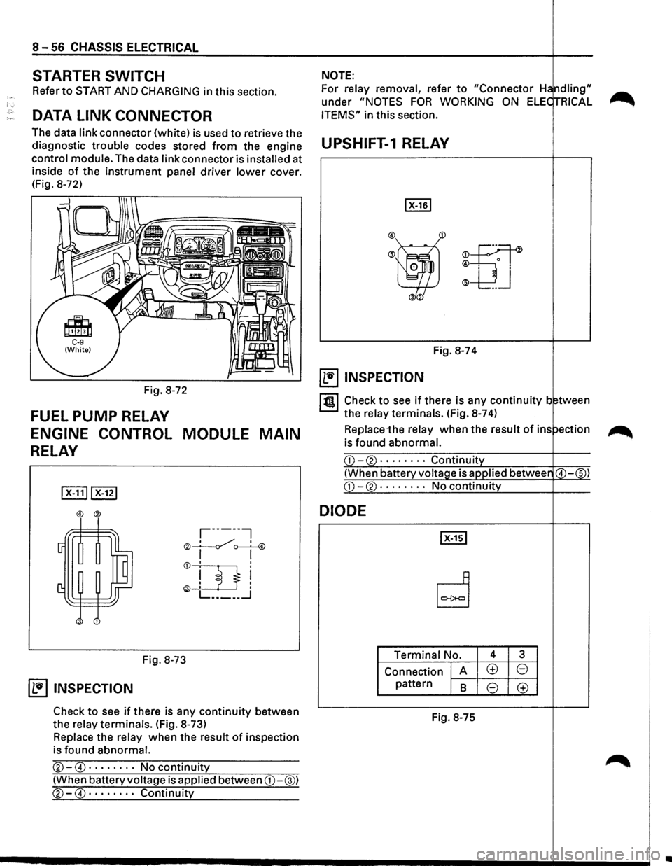
The data
link connector (white) is used to retrieve the
diagnostic
trouble codes stored from the engine UPSHIFT-1 RELAY
control module. The data link connector is installed at .----------------+----.
inside of the instrument panel driver lower cover.
(Fig. 8-72)
Fig. 8-72
FUEL PUMP RELAY
ENGINE CONTROL MODULE MAIN
RELAY
,-------,
"" __!.___./, ' 4 '<)I ~
Fig. 8-73
~ INSPECTION
Check to see if there is any continuity between
the
relay terminals. (Fig. 8-73)
Replace the relay when the result of inspection
is found
abnormal.
®-@ · · · · · · · · No continuity
(When battery voltage is applied between CD-@)
®-@ · · · · · · · · Continuity
m
Fig. 8-74
~ INSPECTION
ltgl Check to see if there is any continuity b tween
the
relay terminals. (Fig. 8-7 4)
Replace the relay when the result of ins ~
is found abnormal.
DIODE
Terminal No. 4 3
Connection A (±) 8
pattern 8 8 (±)
Fig.
8-75
..
Page 1264 of 1928
8-74 CHASSIS ELECTRICAL
FOG LIGHT SWITCH
~ INSPECTION
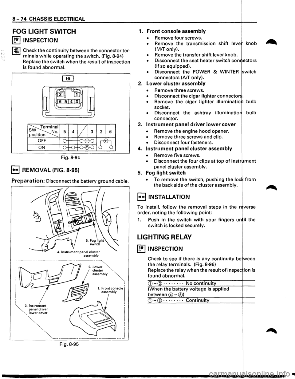
I tgj Check the continuity between the connector ter
minals
while operating the switch. (Fig. 8-94)
Replace the switch when the result of inspection
is found abnormal.
ru~
IT
2 [II
161514131
c-
Fig. 8-94
B REMOVAL (FIG. 8-95)
TI ';
Preparation: Disconnect the battery ground cable.
Fig.
8-95
I I 1. Front console I assembly
1. Front console assembly
• Remove four screws.
• Remove the transmission shift leve knob
(M!r only).
• Remove the transfer shift lever knob.
• Disconnect the seat heater switch con ectors
(If so equipped).
• Disconnect the POWER & WINTER switch
connectors
(A/T only).
2.
Lower cluster assembly
• Remove three screws.
• Disconnect the cigar lighter connector .
• Remove the cigar lighter illuminatio bulb
socket.
• Disconnect the ashtray illuminatio bulb
connector.
3.
Instrument panel driver lower cover
• Remove the engine hood opener.
• Remove three screws and clip.
• Disconnect four fasteners.
4.
Instrument panel cluster assembly
• Remove five screws.
• Disconnect the four clips at top of instr ment
panel cluster assembly.
5. Fog
light switch
• To remove the switch, pushing the loc from
the back side of the cluster assembly.
B INSTALLATION
To install, follow the removal steps in the r verse
order, noting the
following point:
1. Push in the switch with your fingers un il the
switch is locked securely.
LIGHTING RELAY
~ INSPECTION
Check to see if there is any continuity be ween
the relay terminals. (Fig.
8-96)
Replace the relay when the result of in spec ion is
found abnormal.
CD-3 · · · · • · · · No continuit
(When the battery voltage is applied
between
4 -s)
•
Page 1364 of 1928
8-174 CHASSIS ELECTRICAL
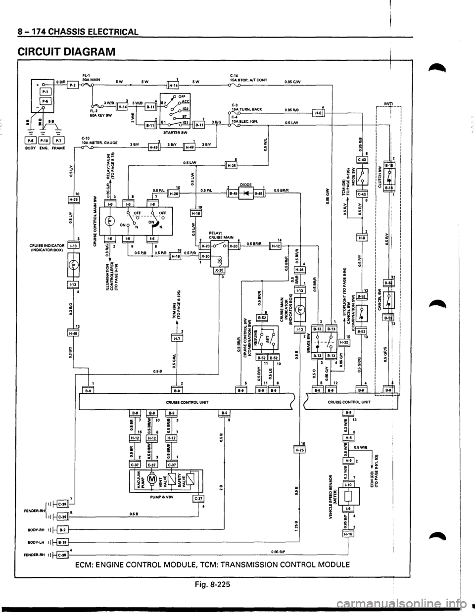
CIRCUIT DIAGRAM
+ BB/R
B
~
sa
=
=
~~~ BODY ENG. FRAME
CRUISE INDICA TOR !INDICATOR BOX)
{II FENDER-RH II
BODY-RH II
BODY-LH II
FENDER-RH II
&W
C-10
10A ME'IIOR, GAUGE
10
C-1' &W sw 15A STOP, AfT CONT
STAR'IIORSW
38('(
O.&Lm ,-----------'-"--'--1-------1 H-25!------'
0.58
8-8
CRUISE ODNTROL UNIT
0.85 G/W
O.SLNJ
~ "' II! 0
~ :
~ g
ECM: ENGINE CONTROL MODULE, TCM: TRANSMISSION CONTROL MODULE
Fig. 8-225
IM/T) r---r--,
..
"' 1:1 0
;: .. :r ~ 1:> ld I
I
I
I
I
I
I
I
I
I
I
I
I
I
I
~I
I I
I
I
I
I
I
~ I
I .. I 0
12
~ .: u
5
•
Page 1375 of 1928
CHASSIS ELECTRICAL 8-185
REAR WHEEL ANTI-LOCK BRAKE SYSTEM (RWAL)
GENERAL DESCRIPTION
The circuit consists of the starter switch, stoplight switch (vehicle w/o cruise control), brake switch (vehicle
w/cruise control). RWAL controller, RWAL speed sensor, RWAL valve, brake differential switch, 4WD switch,
parking brake
SW, indicator light (RWAL, 4WD, BRAKE), and test connector.
In this system, when the service brake is applied the RWAL controller judges the wheel rotation difference
signals which have been sent from the RWAL speed sensor at the rear axle differential. The anti-lock valves
control
the brake fluid pressure which is applied to the rear wheels to prevent the wheels from locking.
When starting the engine, the RWAL indicator in the instrument panel lights up at the same time as the brake
indicator
to inform the driver that the system is operating normally. (The light goes off after two seconds.)
Refer
to Section 5A3, "RWAL (REAR WHEEL ANTI-LOCK BRAKE SYSTEM)" for detail.
Page 1382 of 1928
8-192 CHASSIS ELECTRICAL
TRANSMISSION CONTROL MODULE (TCM)
GENERAL DESCRIPTION
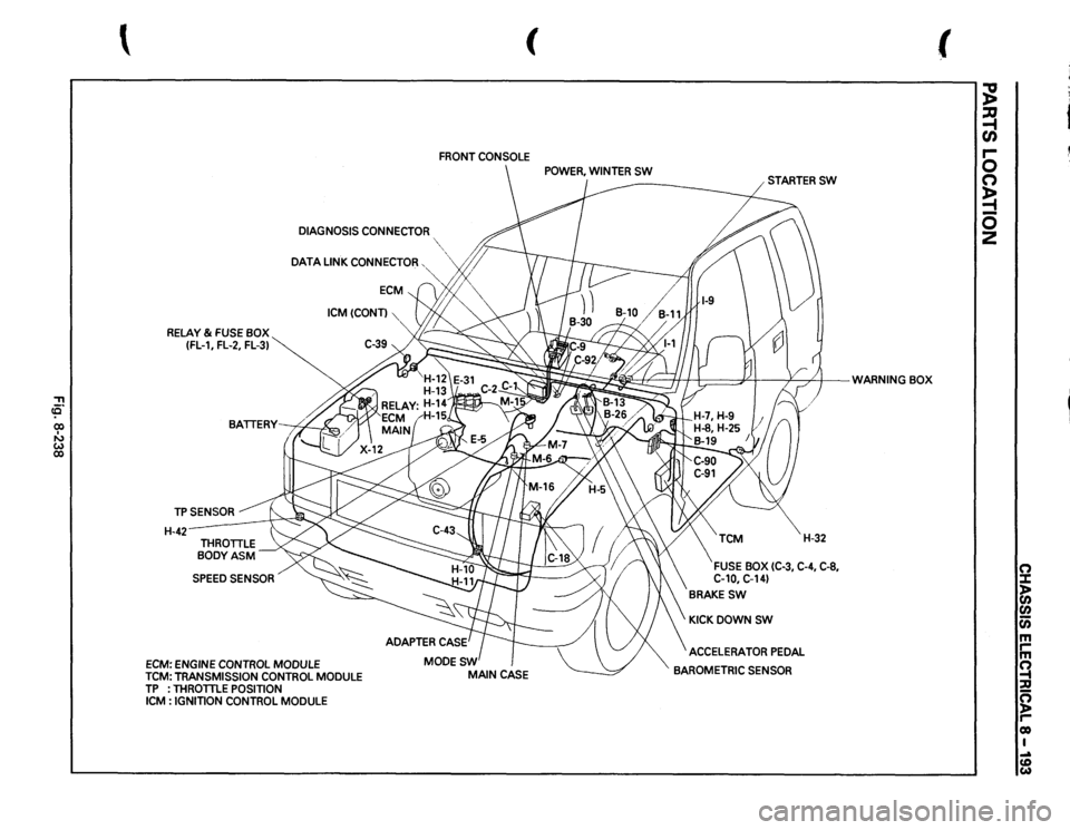
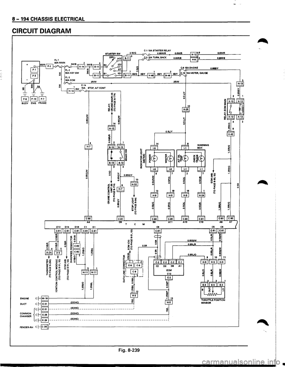
The circuit consists of the starter switch, TCM, mode switch, brake switch, speed sensor, kick down switch,
Power and
Winter switches, Throttle Position (TP) sensor, Engine Control Module (ECM), barometer sensor,
adapter case, main case,
warning light (CHECK TRANS, NT OIL TEMP) and indicator light (WINTER DRIVE,
POWER DRIVE).
The TCM, based on the predetermined shifting characteristics and lockup operating valve, provides the
optimum shifting control to the varying vehicle running condition. The following input signals are sent to the
TCM: select lever position from the mode switch, running mode from the POWER & WINTER switches,
throttle opening from the TP sensor, vehicle speed from the vehicle speed sensor and engine speed from the
ECM are sent to the TCM. After receiving these signals, the TCM determines the vehicle running condition,
and
it sends output signals to each solenoid to control shifting.
When the
TCC solenoid is engaged, the lockup mechanism operates.
The shift
solenoid 2.3 and 1.2/3.4 selects the shift gear position.
The force
motor controls the line pressure to improve shifting.
Also, when the TCM detects an abnormal signal from the transmission or sensor, it will cause the "CHECK
TRANS"
light on the warning box to flash in order to inform the driver of the malfunction.
Refer to section 7 A "AUTOMATIC TRANSMISSION" for details.
•
Page 1383 of 1928
, cE" 00 I I'J w 00
(
FRONT
CONSOLE
DIAGNOSIS
CONNECTOR
"~",
DATA
LINK
CONNECTOR,
·~
RELAY
& FUSE
BOX
(FL-1,
FL-2,
FL-3)
TPSENSOR H-42-
SPEED
SENSOR
ECM:
ENGINE
CONTROL
MODULE
ICM(CONT)
TCM:
TRANSMISSION
CONTROL
MODULE
TP
: THROTTLE
POSITION
ICM
: IGNITION
CONTROL
MODULE
~;
t I:;::==PI
v
/)
WARNING
BOX
' .
!I
/;;'
H-32
FUSE
BOX
(C-3,
C-4, C-8,
C-10,
C-14)
BRAKESW
KICKDOWNSW ACCELERATOR
PEDAL
BAROMETRIC
SENSOR
(
;g ~ en r-0 (") ~ 0 2
0 :::1: )> (I) (I) c;; m rm ~ :;Q ~ co I .... (D w
Page 1384 of 1928
8-194 CHASSIS ELECTRICAL
CIRCUIT DIAGRAM
+
I P~al ~~ ;71 BODY ENG. FRAME
5
~~ o-· 0"1 :;co s~
~~ gt::
i5 ~ ;I
~ :e :e "" ..: £!
ENGINE II M-16
DUCT II E·31 DOHC '
C-1 10A STARTER RELAY 0.85W/R 3 16A TURN, BACK
!i:
" ~~ ol!! 5! i5 0:
COMMON CHAMBER {
II r-8----------_LS9!:1~1_----------------------------_: !
::~ ___________ ;;:~'------------------------------------------------J 7
"' 0
10 H-26
WARNING
BOX
O.&W/R
0.86R/8
0.868/Y
~
~ !(!
~ 0
" ~ ""
FENDER·RH II C·39 1----------------------------------------------------'
Fig. 8-239
•
Page 1388 of 1928
8-198 CHASSIS ELECTRICAL
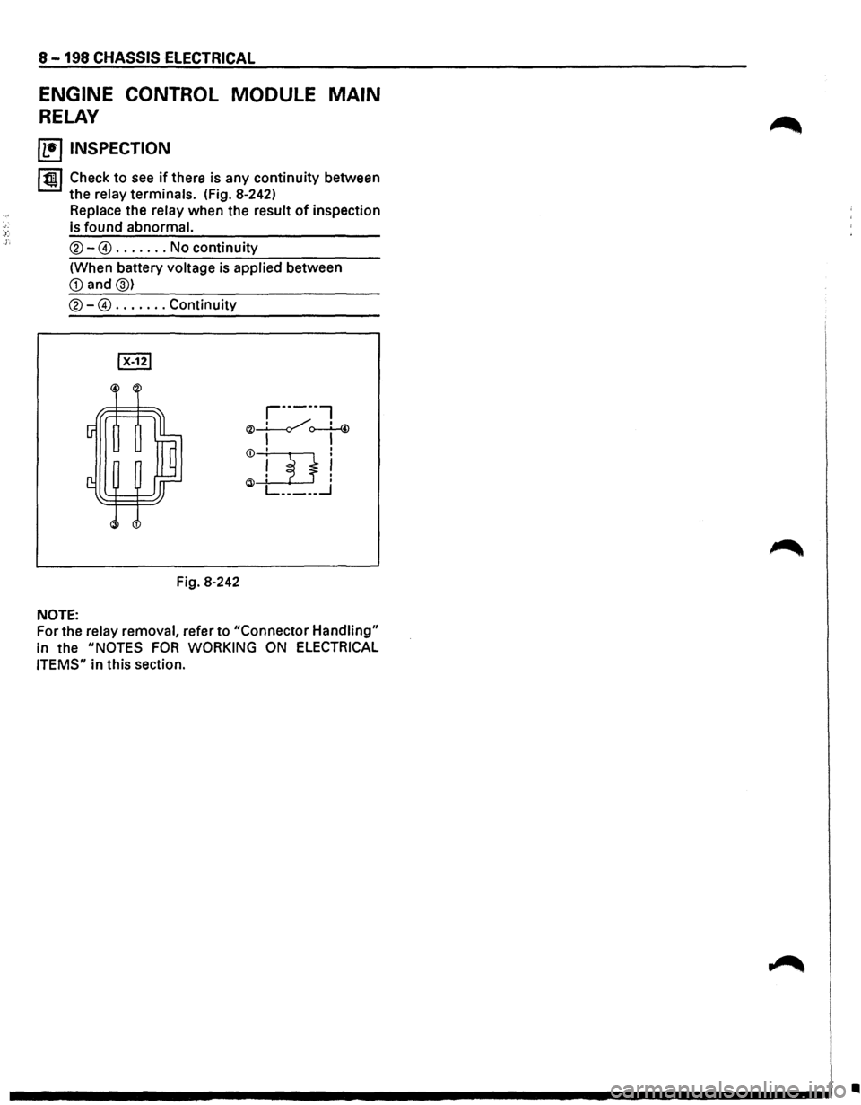
ENGINE CONTROL MODULE MAIN
RELAY
~ INSPECTION
1~1 Check to see if there is any continuity between
the relay terminals. (fig. 8-242)
Replace the relay when
the result of inspection
is
found abnormal.
®-@ ....... No continuity
(When battery voltage is applied between
G) and@)
®-@ ....... Continuity
Fig. 8-242
NOTE:
r-----~
®__1__/ o---!-@
I I CD I :
ill! ~ ' L _____ .J
For the relay removal, refer to "Connector Handling"
in the "NOTES FOR WORKING ON ELECTRICAL
ITEMS"
in this section.
•
Page 1460 of 1928
8-270 CHASSIS ELECTRICAL
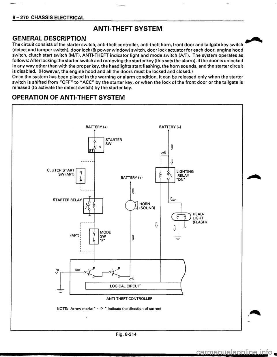
ANTI-THEFT SYSTEM
GENERAL DESCRIPTION .......
The circuit consists ofthe starter switch, anti-theft controller, anti-theft horn, front door and tailgate key switch
(detect and tamper switch),
door lock (&power window) switch, door lock actuator for each door, engine hood
switch, clutch start switch (MfT),
ANTI-THEFT indicator light and mode switch (AfT). The system operates as
follows: After locking the starter switch and removing the starter key (this sets the alarm),
ifthe door is unlocked
in any
way other than with the proper key, the headlights start flashing, the horn sounds, and the starter circuit
is disabled. (However,
the engine hood and all the doors must be locked and closed.)
Once the system has been placed in the warning or alarm condition, it can be released only when the starter
switch is shifted
from "OFF" to "ACC" by the starter key, or when the lock of the front door or the tailgate is
released (to activate the detect switch)
by the starter key.
OPERATION OF ANTI-THEFT SYSTEM
'
'
CLUTCH START m
SW(M/Tiw
' '
'
BATIERY(+)
0 ST
STARTER sw
BATIERY(+)
L------
STARTER RELAY
' ' (MIT):
'
'
'
HORN
(SOUND)
ANTI-THEFT CONTROLLER
BATIERY(+)
LIGHTING
RELAY
"ON"
HEADLIGHT (FLASH)
NOTE: Arrow marks u ~ u indicate the direction of current
Fig. 8-314
•
Page 1465 of 1928
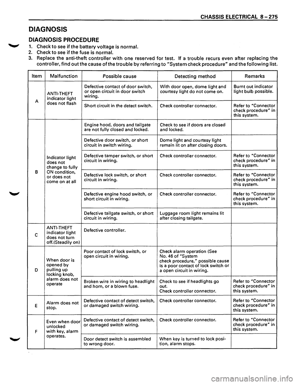
DIAGNOSIS
DIAGNOSIS PROCEDURE
.......,. 1. Check to see ifthe battery voltage is normal.
2. Check to see if the fuse is normal.
CHASSIS ELECTRICAL 8 -275
3. Replace the anti-theft controller with one reserved for test. If a trouble recurs even after replacing the
controller, find
out the cause of the trouble by referring to "System check procedure" and the following list.
Item Malfunction
Possible
cause Detecting method Remarks
Defective
contact of door switch,
With door open, dome light and Burnt
out indicator
ANTI-THEFT or open circuit in door switch courtesy light do not come on. light bulb possible.
indicator light wiring.
A does
not flash Short circuit in the detect switch.
Check controller connector. Refer to "Connector check procedure" in
this system.
Engine hood, doors and
tailgate Check to see if doors are closed are not fully closed and locked. and locked.
Defective door switch, or short Dome light and courtesy light circuit in switch wiring.
remain lit on after closing doors.
Indicator light Defective tamper switch, or short Check controller connector. Refer
to "Connector
does not circuit in wiring. check procedure" in
change to
fully this system.
B
ON condition, Defective lock switch, or short Check controller connector. Refer
to "Connector or does not come on at all circuit in wiring. check procedure" in
this system.
Defective engine hood switch, or Check
controller connector. Refer
to "Connector
short circuit in wiring. check
procedure" in
this system.
Defective
tailgate switch, or short Luggage room light remains lit circuit in wiring. after closing tailgate.
ANTI-THEFT
Defective controller.
c indicator light
does not turn off.(Steadily on) Poor contact
of lock switch, or Check alarm operation (See
When
door is open
circuit in wiring. No. 46 of "System
check procedure," possible cause
opened by
is a poor contact of lock switch or D pulling up
a open circuit in wiring. locking knob, alarm does not Broken wire in wiring to headlight Check to see if headlights go Refer
to "Connector operate
and horn, or a blown fuse. out. check procedure" in
Check
controller connector. this
system.
Alarm does not Defective contact of detect switch, Check controller connector.
Refer to "Connector
E
stop. or damaged switch wiring. check procedure" in
this system.
Even when
door Defective contact of detect switch, Check controller connector. Refer
to "Connector
unlocked
or damaged switch wiring. check procedure" in
F
with key, alarm this system.
operates. Door detect switch is
assembled When key is turned to lock posi-
to
wrong door. tion, alarm stops.