engine ISUZU TROOPER 1995 Workshop Manual
[x] Cancel search | Manufacturer: ISUZU, Model Year: 1995, Model line: TROOPER, Model: ISUZU TROOPER 1995Pages: 1928
Page 1192 of 1928
-·*; ~---
8-2 CHASSIS ELECTRICAL
GENERAL INFORMATION
The chassis electrical system is of 12-volt specifications with a negative ground polarity.
Wire sizes are appropriate
to respective circuits, and classified by color. (The classification of harnesses by
color is shown on the circuit diagram for ease of harness identification.)
The
wire size is determined by load capacity and the length of wire required.
The
vehicle harnesses are: body harness, chassis harness, engine room harness, instrument harness,
transmission harness, engine
ECGI harness, dome light harness, door harness, rear body harness, tailgate
harness,
SRS harness and battery cables.
The harnesses are protected either
by tape or corrugated tube, depending on harness location.
The circuit
for each system consists of the power source, wire, fuse, relay, switch, load parts and ground, all of
which are shown on the circuit diagram.
In this manual, each electrical device is classified by system. For major parts shown on the circuit based on
the circuit diagram
for each system, a summary, diagnosis oftroubles, inspection and removal and installation
procedures are detailed.
NOTES FOR WORKING ON ELECTRICAL ITEMS
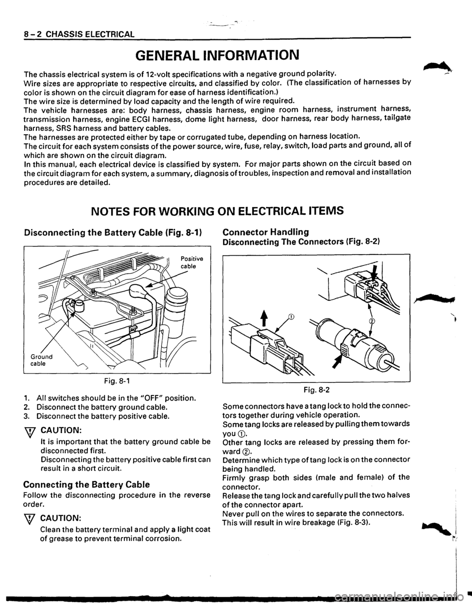
Disconnecting the Battery Cable (Fig. 8-1)
Ground cable
Fig. 8-1
1. All switches should be in the "OFF" position.
2. Disconnect the battery ground cable.
3. Disconnect the battery positive cable.
W CAUTION:
It is important that the battery ground cable be
disconnected first.
Disconnecting the battery positive cable first can
result in a short circuit.
Connecting the Battery Cable
Follow the disconnecting procedure in the reverse
order.
\V CAUTION:
Clean the battery terminal and apply a light coat
of grease to prevent terminal corrosion.
Connector Handling
Disconnecting The Connectors (Fig. 8-2)
Fig. 8-2
Some connectors have a tang lock to hold the connec
tors together during vehicle operation.
Some tang locks are released by pulling them towards
you
G).
Other tang locks are released by pressing them for
ward®.
Determine which type oftang lock is on the connector
being handled.
Firmly grasp both sides (male and female)
of the
connector. Release the tang lock and carefully pull the
two halves
of the connector apart.
Never pull on the wires
to separate the connectors.
This
will result in wire breakage (Fig. 8-3).
.,
..
Page 1195 of 1928
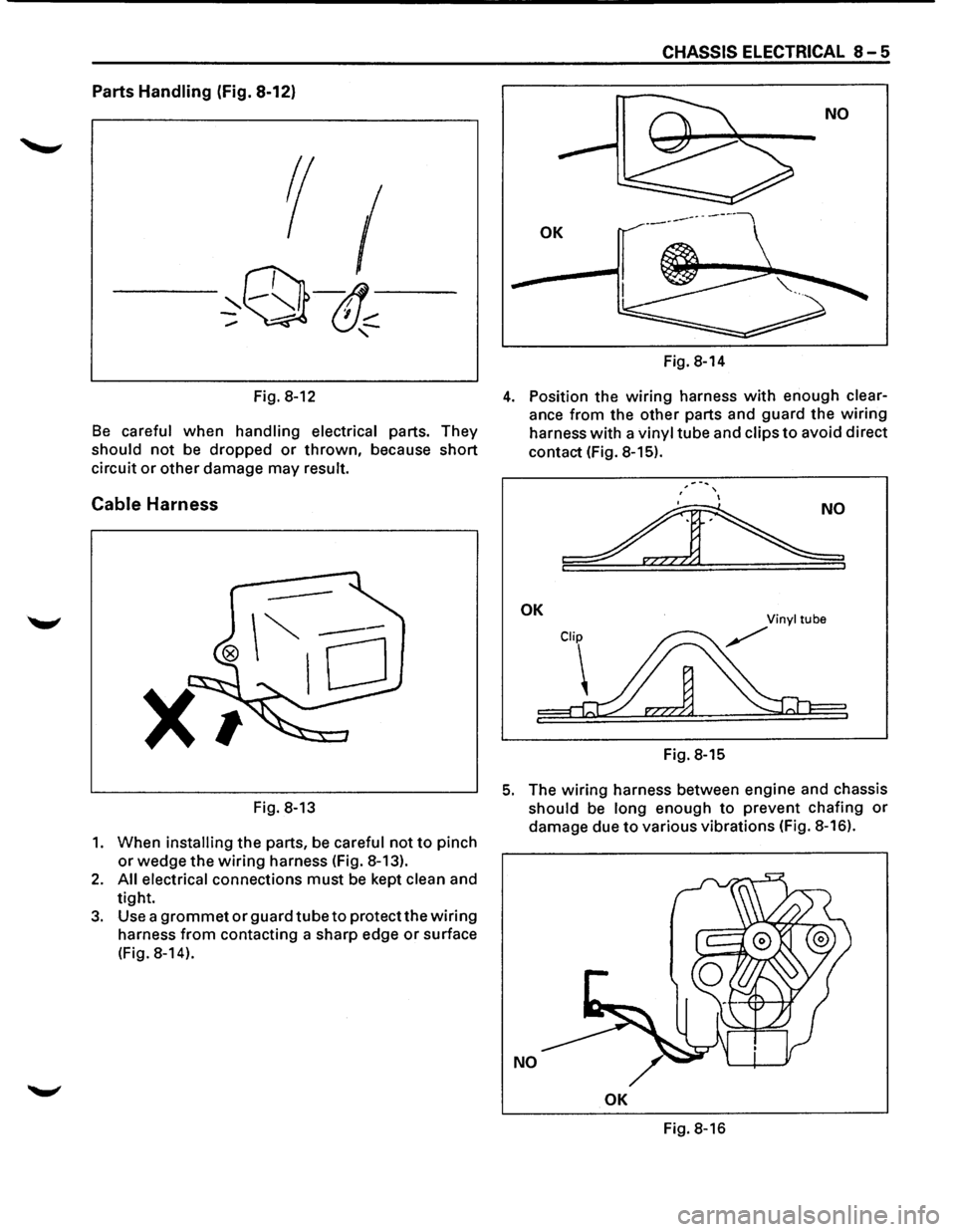
Parts Handling (Fig. 8-12)
Fig. 8-12
Be careful when handling electrical parts. They
should
not be dropped or thrown, because short
circuit
or other damage may result.
Cable Harness
--
Xt
Fig. 8-13
1. When installing the parts, be careful not to pinch
or wedge the wiring harness (Fig. 8-13).
2. All electrical connections must be kept clean and
tight.
3. Use a grommet orguardtubeto protect the wiring
harness from contacting a sharp edge or surface
(Fig.
8-14).
CHASSIS ELECTRICAL 8-5
Fig. 8-14
4. Position the wiring harness with enough clear
ance from the other parts and guard the wiring
harness with a vinyl tube and clips to avoid direct
contact (Fig.
8-15).
', '
~
OK
Fig. 8-15
5. The wiring harness between engine and chassis
should be long enough
to prevent chafing or
damage due to various vibrations (Fig. 8-16).
NO
OK
Fig. 8-16
Page 1199 of 1928
CHASSIS ELECTRICAL 8-9
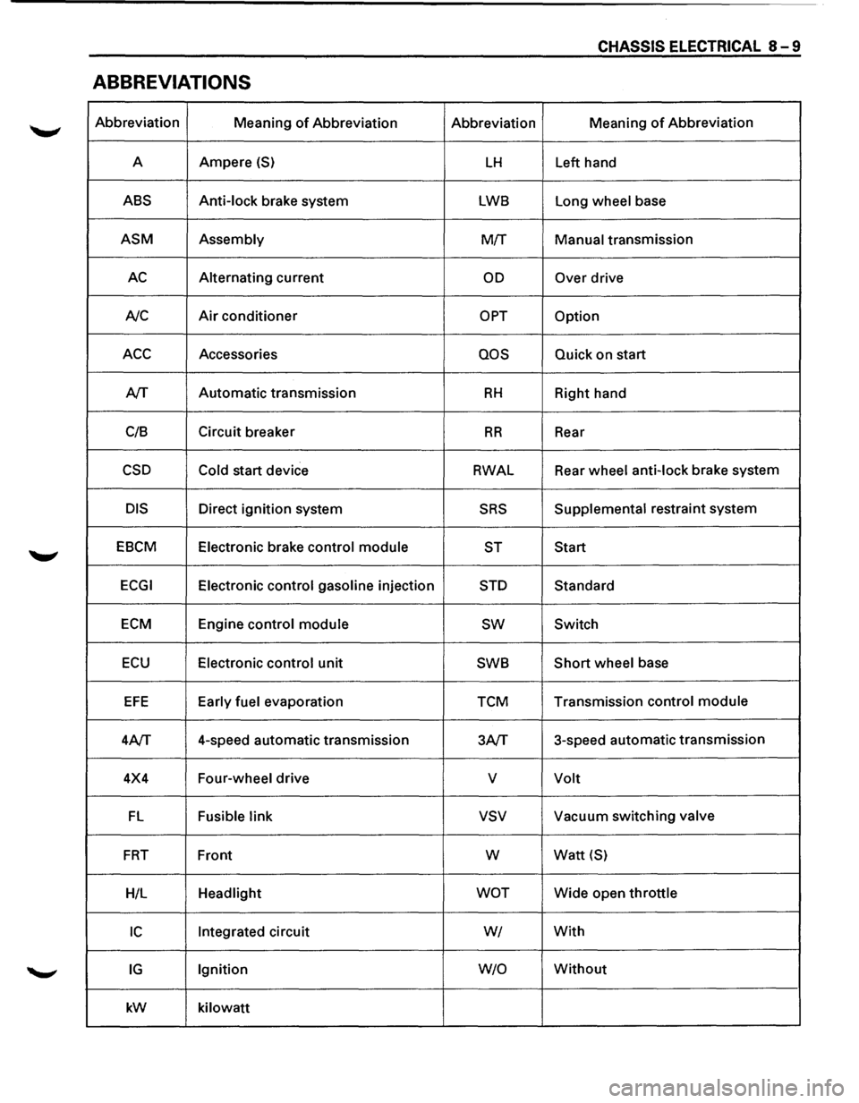
ABBREVIATIONS
Abbreviation
Meaning of Abbreviation Abbreviation Meaning of Abbreviation
A Ampere
(S) LH Left
hand
ABS Anti-lock brake system LWB Long wheel base
ASM Assembly M!f Manual transmission
AC Alternating current OD Over drive
A/C
Air conditioner OPT Option
ACC Accessories QOS Quick on start
A/T Automatic
transmission
RH Right hand
C/8 Circuit
breaker
RR Rear
CSD Cold start device RWAL Rear
wheel anti-lock brake system
DIS Direct ignition system SRS Supplemental restraint system
EBCM Electronic brake control module
ST Start
ECGI Electronic control gasoline injection STD Standard
ECM Engine control module sw Switch
ECU Electronic control unit SWB Short wheel
base
EFE Early fuel evaporation TCM Transmission
control module
4A/T 4-speed
automatic transmission
3A/T 3-speed
automatic transmission
4X4 Four-wheel drive
v Volt
FL Fusible link vsv Vacuum switching valve
FRT Front w Watt {S)
H/L Headlight WOT Wide open throttle
IC Integrated circuit WI With
IG Ignition W/0 Without
kW
kilowatt
Page 1210 of 1928
8-20 CHASSIS ELECTRICAL
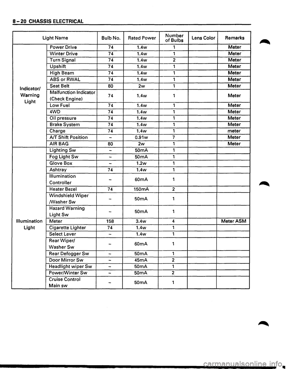
Light Name Bulb No. Rated Power Number Lens Color Remarks of Bulbs
Power Drive 74 1.4w 1
Meter
Winter Drive 74 1.4w
1 Meter
Turn Signal 74 1.4w 2 Meter
Upshift
74 1.4w 1 Meter
High Beam
74 1.4w 1 Meter
ABSorRWAL 74 1.4w 1 Meter
Indicator/ Seat Belt 80 2w 1 Meter
Warning Malfunction Indicator 74 1.4w
1 Meter
Light (Check
Engine)
Low Fuel 74 1.4w 1 Meter
4WD
74 1.4w 1 Meter
Oil pressure 74 1.4w 1 Meter
Brake System 74 1.4w 1 Meter
Charge 74 1.4w 1
meter
A/T Shift Position -0.91w 7 Meter
AIR BAG 80 2w 1 Meter
Lighting Sw -SOmA 1
Fog Light
Sw -SOmA 1
Glove Box -1.2w 1
Ashtray
74 1.4w 1
Illumination
60mA 1 -Controller
Heater Bezel 74 1SOmA 2
Windshield
Wiper SOmA 1 -/WasherSw
Hazard Warning SOmA 1 -Light Sw
Illumination Meter 158 3.4w 4 MeterASM
Light
Cigarette Lighter
74 1.4w
1
Select Lever -1.4w 1
Rear
Wiper/ 60mA 1 -WasherSw
Rear Defogger Sw -SOmA 1
Door
Mirror Sw -45mA 2
Headlight
wiper Sw -SOmA 1
Power/Winter
Sw -SOmA 2
Cruise Control
SOmA 1 -Main sw
II
Page 1211 of 1928
CHASSIS ELECTRICAL 8-21
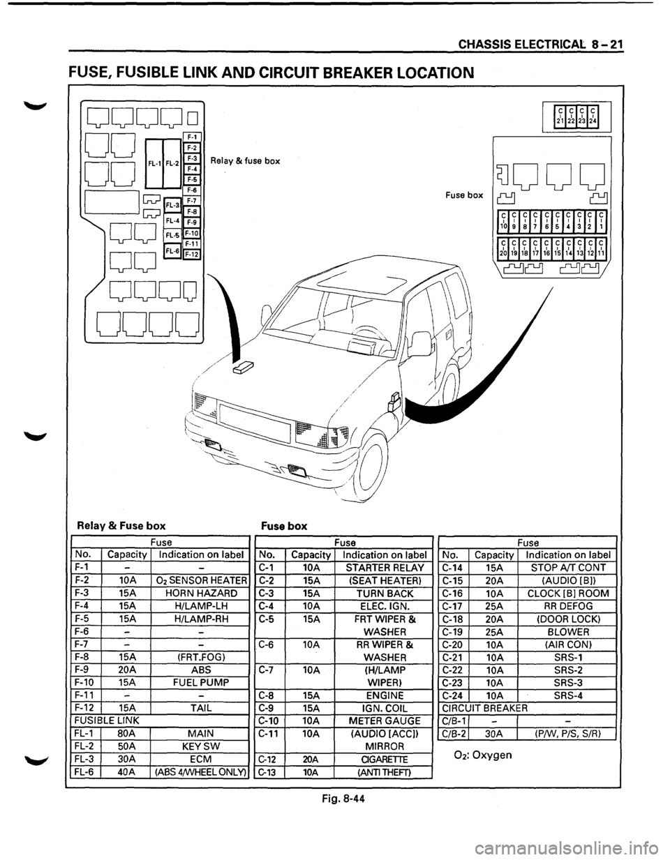
FUSE, FUSIBLE LINK AND CIRCUIT BREAKER LOCATION
ooooo 112~12~1~1~1
00 E
EEr 00 ~
Relay & fuse box
SJOOO 7-6
I lw ;;::;~ Fuse box ~ ~
1l1~~ ~lff~UIH~Inll
w~ F-a FL-4 ~
00 FL·S~ r---, F-11 'l2~J1~ 1~1&11~11~1,\l~31hl1~1
0
0
FL-6 'F-i2
I' ~
\a~ a~;
0000
0000
I ~
l/
~
j
~/~/ e:;?' v II I / / .I / /
('-/ .
~~
-~-~;,a~ ~~ --.:_
~~~~ -
Relay & Fuse box Fuse box
Fuse
Fuse Fuse
No. Capacity Indication on label No. Capacity Indication on label No. Capacity Indication on label
F-1 --C-1 10A STARTER RELAY
C-14 15A STOP A!f CONT
F-2 10A 02 SENSOR HEATER C-2 15A (SEAT HEATER)
C-15 20A (AUDIO [8))
F-3
15A HORN HAZARD C-3 15A
TURN BACK C-16 10A CLOCK (8] ROOM
F-4
15A H/LAMP-LH C-4 10A ELEC.IGN. C-17 25A RR DEFOG
F-5
15A H/LAMP-RH C-5
15A FRTWIPER & C-18 20A (DOOR LOCK)
F-6 --WASHER C-19
25A BLOWER
F-7
- -C-6 10A RRWIPER & C-20 10A (AIR
CON)
F-8
15A (FRT.FOG) WASHER C-21 10A SRS-1
F-9 20A ABS C-7 10A (H/LAMP C-22 10A SRS-2
F-10
15A FUEL PUMP WIPER) C-23 lOA SRS-3
F-11 -
-C-8 15A ENGINE C-24 10A SRS-4
F-12
15A TAIL C-9 15A IGN. COIL CIRCUIT BREAKER
FUSIBLE
LINK
C-10 10A METER GAUGE
C/8-1 --FL-1 80A MAIN C-11 10A
(AUDIO IACC])
C/8-2 30A (P/W, P/S, S/R)
FL-2 50 A KEYSW MIRROR
FL-3 30A ECM C-12 20A CIGARETTE 02: Oxygen
FL-6 40A (ASS 4/WHEEL ONLY) C-13 10A (ANTI THEFT)
Fig. 8-44
Page 1212 of 1928
8-22 CHASSIS ELECTRICAL
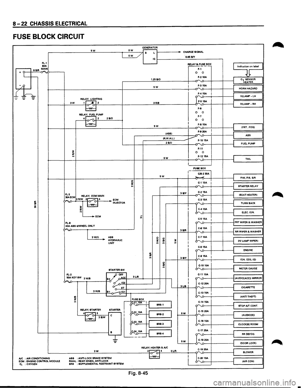
FUSE BLOCK CIRCUIT
GENERATOR -------------------~s~w~------------~~s~w~--~~~~ r- / B L 1------CHARGE SIGNAL &W _/
FL-1 80A .-----, B 11.'1 MAIN
+ Lt--
l£h
~----/ IG~----------~O~.$~B/V~-----------,
3W REL~HT1NG 1J ---'"~L 3
RELA~PUMP 4 1...---. 12 2 B/0
1.25 B/0
SW
3RJ8
5W
~~~·~ F-1 0 0 F-2 10A
I F-315A
F-8
0 0 F-7 0 0 F-81SA
F-920A
9;nlaool
I
Oz SENSOR HEATER
HORN HAZARD
H/LAMP-LH
H/LAMP-RH
(FRT. FOG)
lABS) -I ABS
I ,--------__:<;;:R·.:.:W.::..Acc·L;;:-1 ____ ----Jv F-10 1SA 2 810
I
~ECM RELAY; ECM MAIN ¢~,...,..J>--+2'-'RIW~_::2~1-o.....-<:>-f-·4.:._ __ _. ~J~CTOR
L...-_.ECM
FL-t 40A ABS 4/WHEEL ONLY
"
.... ...
SW
5W
3 8IY
F-11 0 0 F-1215A
~------' FUSE BOX
CIB-2 30A ~.,.;
C-110A :
C-215A
C-31SA
C-410A
I
J
FUEL PUMP
TAIL
P/W, PIS. SIR
STARTER RELAY
(SEAT HEATER)
TURN BACK
ELEC.IGN.
e-s
15A 1 ""'-.0---t-----+----il FRT WIPER & WASHER
"""' -
I 3W/G
C-810A '---f-+----+.:3.:BIR::::..+---¢""''-£>---i-----f-----jl RR WIPER & WASHER
ABS HYORAULIC UNIT
STARTERSW
FL-2 _JJ OFF
~ ...
..:..AKEYSW 3 W/B ay ' o.N". 3UB
~~--~--~,~------~-0 ~~IG~2Y-----------~ o-: ST 3W/B 81 -.,IG1
FUSE BOX
I
I g1~ 1 J'-:::s:R:s-:1 =I RELAY; STARTER
STARTER I r-
L~---'~-j.t
I I 3UB
sw
C-710A
~';::--~--~-'---~~~HI~LA~M~P~W~IP~E~R~l~~ C-81SA ""'-'>--1---...__---i ENGINE
C-111SA I J~======~l IGN. COIL (G)
C-10 10A
C-1110A
k'-1:>----t----t
~==~I
METER GAUGE
""''-£>---f----------1 (AUDIO[ACC)) MIRROR
C-12 20A
::...1310A I
C-141SA -r"\'-1)----f----t
C-15 20A L,-.
CIGARETTE
(ANTITHEFT)
STOP A/T CONT.
(AUDIO[ B))
C-1810A """"-'-.0---f----------t_j CLOCK[B) ROOM
L---+------------------------iB lt~;_ ~=~~~:~:~::~~~: C-17 2SA I
G1820A
RR DEFOG
= sw (DOOR LOCK) RELAY; HEATER &A/C .:._ __________________ .:.:3~W'-'---------------------~2to~.....-4 3UR C-19 2SA ...... BLOWER
A/C : AIR CONDITIONING ECM : ENGINE CONTIIOL MODULE 0, :OXYGEN ABS
:ANTI-LOCK
BRAKE BYBTEM
RWAL: REAR WHEEL ANTI-LOCK BRB : SUPPLEMENTAL RESTRAINT SYSTEM
C-20 10A (AIR CON)
Fig. 8-45
•
Page 1214 of 1928
8-24 CHASSIS ELECTRICAL
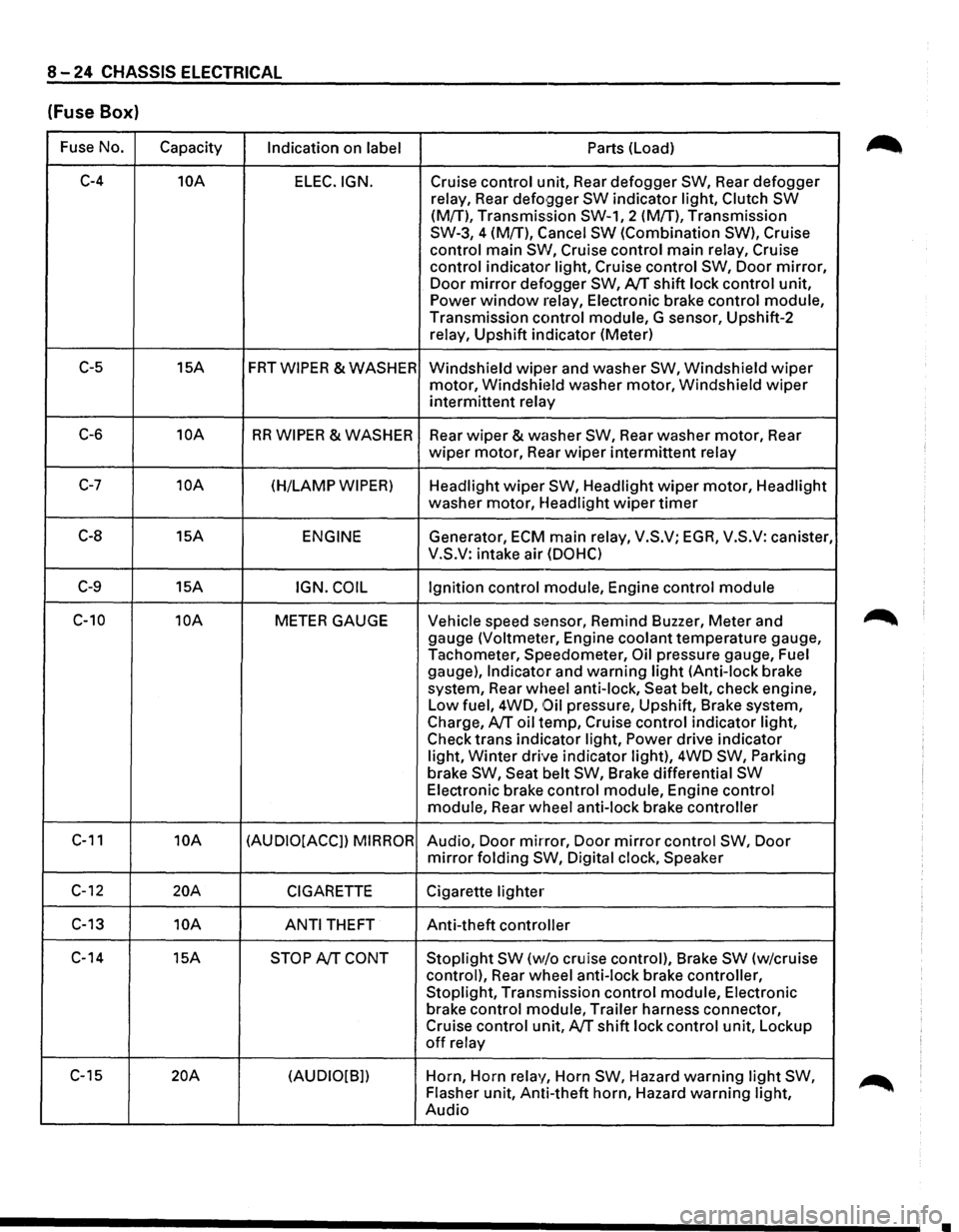
(Fuse Box)
Fuse No.
Capacity Indication on label Parts (Load)
C-4 10A
ELEC.IGN. Cruise control unit, Rear defogger SW, Rear defogger
relay, Rear
defo9ger SW indicator light, Clutch SW
(M{T), Transmission SW-1, 2 (M!T), Transmission
SW-3, 4 (M{T), Cancel
SW (Combination SW), Cruise
control main
SW, Cruise control main relay, Cruise
control indicator light, Cruise control
SW, Door mirror,
Door mirror defogger SW, AfT shift lock control unit,
Power window relay, Electronic brake control module,
Transmission control module, G sensor, Upshift-2
relay, Upshift indicator (Meter)
C-5 15A FRTWIPER &WASHER
Windshield wipt~r and washer SW, Windshield wiper
motor, Windshit~ld washer motor, Windshield wiper
intermittent relay
C-6 10A RR WIPER & WASHER
Rear wiper & washer SW, Rear washer motor, Rear
wiper motor, Rear wiper intermittent relay
C-7 10A (H/LAMP WIPER) Headlight wiper SW, Headlight wiper motor, Headlight
washer motor, Headlight
wiper timer
C-8 15A ENGINE Generator, ECM main relay, V.S.V; EGA, V.S.V: canister,
V.S.V: intake air
(DOHC)
C-9 15A IGN. COIL Ignition control module, Engine control module
C-10 10A METER GAUGE Vehicle speed stmsor, Remind Buzzer, Meter and
gauge
(Voltmeter, Engine coolant temperature gauge,
Tachometer, Speedometer,
Oil pressure gauge, Fuel
gauge),
Indicator and warning light (Anti-lock brake
system, Rear wheel anti-lock, Seat belt, check engine,
Low fuel, 4WD,
Oil pressure, Upshift, Brake system,
Charge,
AfT oil temp, Cruise control indicator light,
Check trans indicator light,
Power drive indicator
light,
Winter drive indicator light), 4WD SW, Parking
brake SW, Seat belt SW, Brake differential SW
Electronic brake control module, Engine control
module, Rear wheel anti-lock brake controller
C-11 10A (AUDIO[ACCJ) MIRROR Audio, Door mirror, Door mirror control SW, Door
mirror folding SW, Digital clock, Speaker
C-12 20A CIGARETTE Cigarette lighter
C-13 10A
ANTI THEFT Anti-theft controller
C-14 15A
STOP AfT CONT Stoplight SW (w/o cruise control), Brake SW (w/cruise
control), Rear wheel anti-lock brake controller,
Stoplight, Transmission control module, Electronic
brake control module, Trailer harness connector,
Cruise control unit,
AfT shift lock control unit, Lockup
off relay
C-15
20A (AUDIO[B]) Horn,
Horn relay, Horn SW, Hazard warning light SW,
Flasher unit, Anti-theft horn, Hazard warning light,
Audio
•
Page 1215 of 1928
CHASSIS ELECTRICAL 8-25
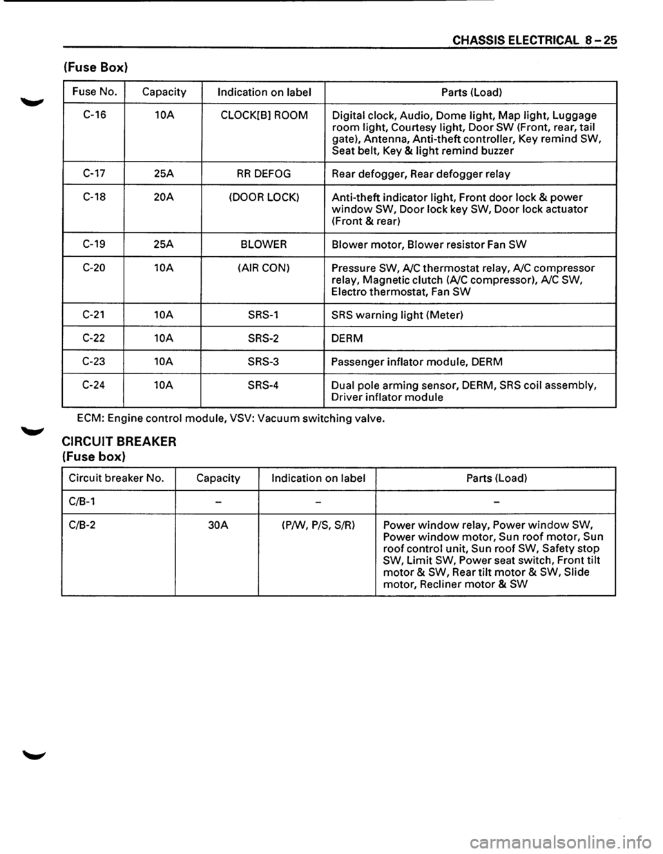
(fuse Box)
Fuse No.
Capacity Indication on label Parts
(Load)
C-16
10A
CLOCK[B] ROOM Digital clock, Audio, Dome light, Map light, Luggage
room light, Courtesy light, Door SW (Front, rear, tail
gate), Antenna, Anti-theft controller, Key remind SW,
Seat belt, Key & light remind buzzer
C-17 25A RR DEFOG Rear defogger, Rear defogger relay
C-18 20A (DOOR LOCK) Anti-theft indicator light, Front door lock & power
window SW, Door lock key SW, Door lock actuator
(Front
& rear)
C-19 25A BLOWER Blower motor, Blower resistor Fan SW
C-20 10A (AIR CON) Pressure SW, A/C thermostat relay, A/C compressor
relay, Magnetic clutch
(A/C compressor), A/C SW,
Electro thermostat, Fan SW
C-21 10A SRS-1 SRS warning light (Meter)
C-22 10A SRS-2 DERM
C-23
10A SRS-3 Passenger inflator module, DERM
C-24
10A SRS-4 Dual pole arming sensor, DERM, SRS coil assembly,
Driver inflator module
ECM: Engine control module, VSV: Vacuum switching valve.
CIRCUIT BREAKER
(fuse box)
Circuit breaker No.
C/B-1
C/B-2
Capacity
-
30A
Indication on label
-
(P/W, P/S, S/R)
Parts (Load)
-
Power window relay, Power window SW,
Power window motor, Sun roof motor, Sun
roof control unit, Sun roof SW, Safety stop
SW, Limit SW, Power seat switch, Front tilt
motor & SW, Rear tilt motor & SW, Slide
motor, Recliner
motor & SW
Page 1216 of 1928
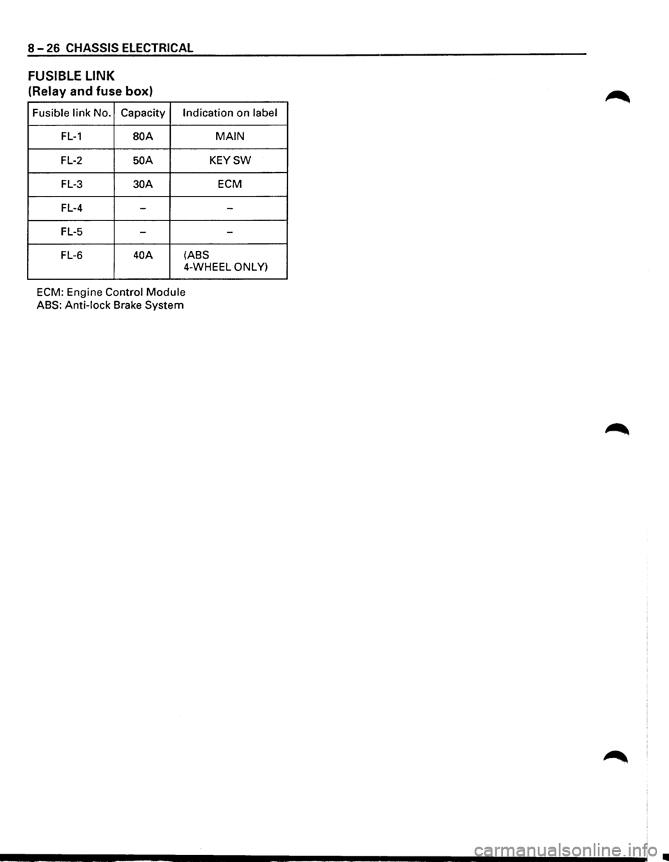
8 -26 CHASSIS ELECTRICAL
FUSIBLE LINK
(Relay and fuse box)
Fusible link No. Capacity Indication on label
FL-1 BOA MAIN
FL-2 50 A KEYSW
FL-3 30A ECM
FL-4
- -
FL-5 --
FL-6 40A (ABS
4-WHEEL ONLY)
ECM: Engine Control Module
ABS: Anti-lock Brake System
•
Page 1217 of 1928
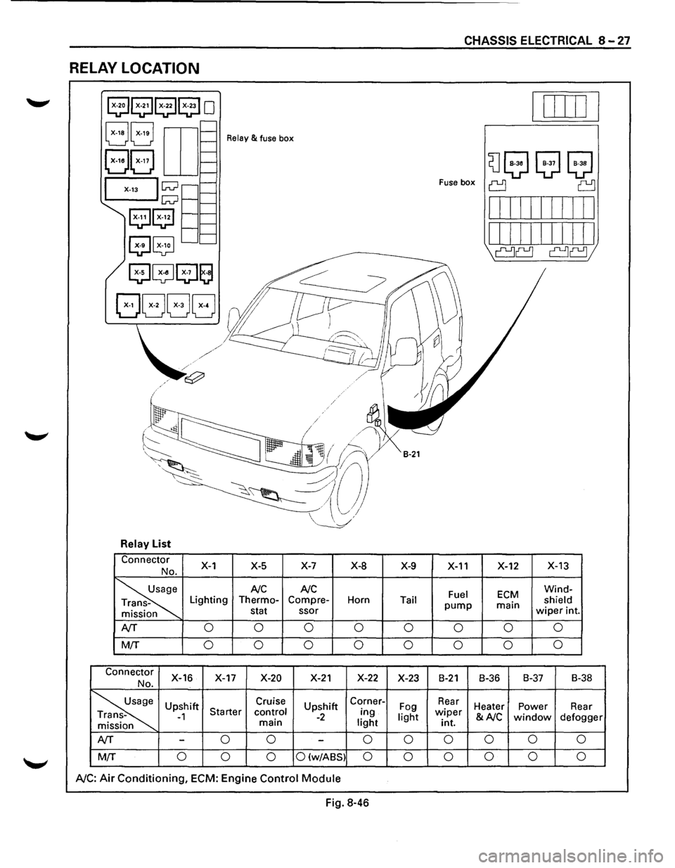
RELAY LOCATION
Relay & fuse box
Relay List
Connector X-1 X-5 X-7
X-8
No.
~
NC NC Lighting Thermo-Com pre-
Horn -stat ssor
n
NT 0 0 0 0
M(f 0 0 0
0
Connector
X-16 X-17 X-20 X-21 X-22
No.
~
Upshift Cruise Upshift Corner-
-1 Starter control -2 ing -main light n
NT -0 0 -0
M!f 0 0 0 0(w/A8S) 0
AJC: Air Conditioning, ECM: Engine Control Module
Fig. 8-46
B-21
X-9
Tail
0
0
X-23
Fog
light
0
0
CHASSIS ELECTRICAL 8-27
Fuse box
X-11
Fuel pump
0
0
8-21
II]]]J I
~8~8
c:J c:J
11111111111
111111
IIIII
BB a B
X-12 X-13
ECM Wind-
main shield wiper int.
0
0
0 0
8-36
8-37
8-38
Rear Heater Power Rear
wiper int. &NC window defogger
0
0 0
0
0 0 0
0