brakes ISUZU TROOPER 1995 Repair Manual
[x] Cancel search | Manufacturer: ISUZU, Model Year: 1995, Model line: TROOPER, Model: ISUZU TROOPER 1995Pages: 1928
Page 384 of 1928
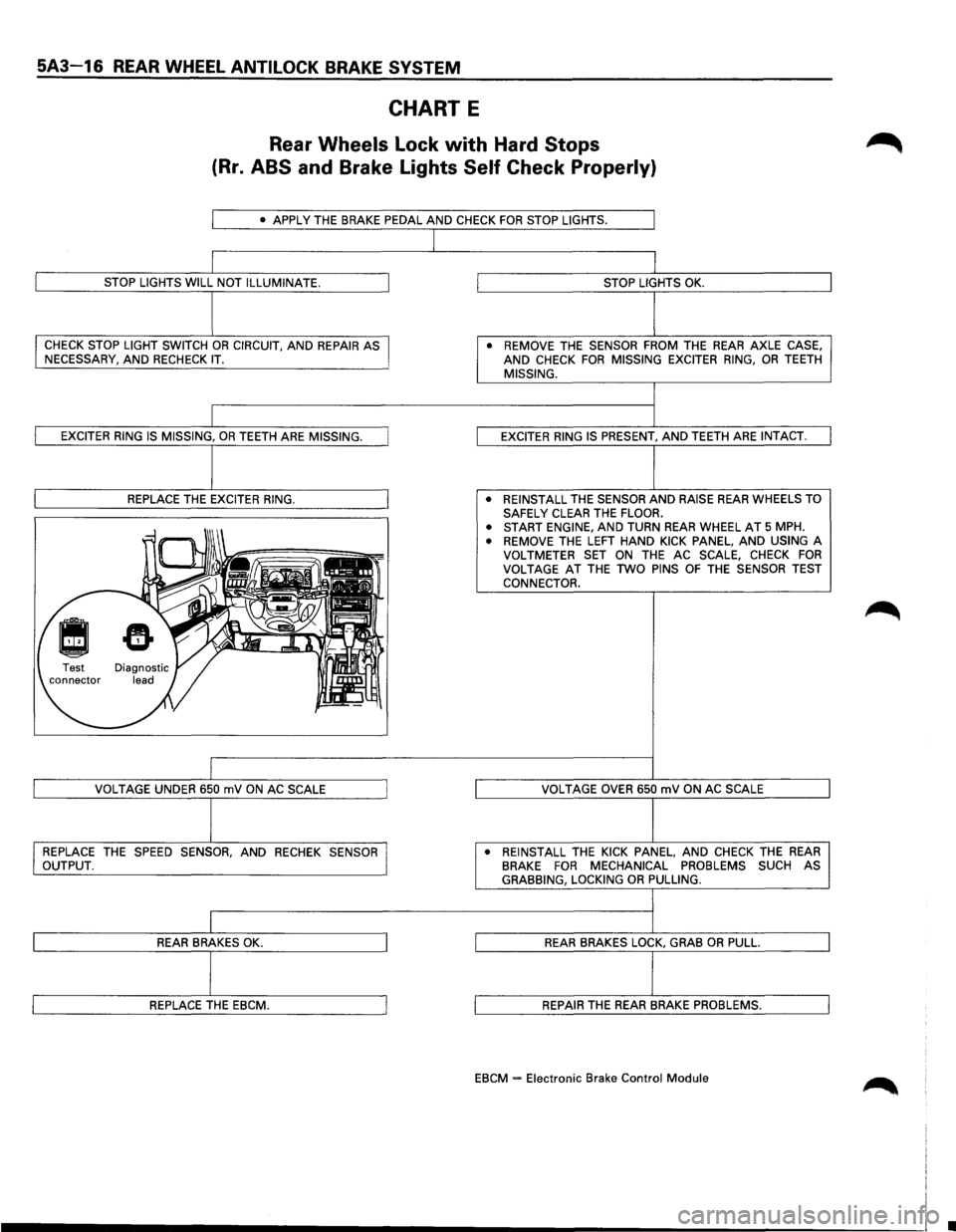
5A3-16 REAR WHEEL ANTILOCK BRAKE SYSTEM
CHART E
Rear Wheels Lock with Hard Stops
(Rr. ABS and Brake Lights Self Check Properly)
• APPLY THE BRAKE PEDAL AND CHECK FOR STOP LIGHTS.
STOP LIGHTS WILL NOT ILLUMINATE.
CHECK STOP LIGHT SWITCH OR CIRCUIT, AND REPAIR AS
NECESSARY, AND RECHECK IT.
EXCITER RING IS MISSING, OR TEETH ARE MISSING.
REPLACE
THE EXCITER RING.
VOLTAGE
UNDER 650 mV ON AC SCALE
REPLACE
THE SPEED SENSOR, AND RECHEK SENSOR
OUTPUT.
REAR BRAKES OK.
REPLACE THE EBCM.
STOP LIGHTS OK.
• REMOVE THE SENSOR FROM THE REAR AXLE CASE, AND CHECK FOR MISSING EXCITER RING, OR TEETH MISSING.
EXCITER
RING IS PRESENT, AND TEETH ARE INTACT.
• REINSTALL
THE SENSOR AND RAISE REAR WHEELS TO
SAFELY CLEAR THE FLOOR.
• START ENGINE, AND TURN REAR WHEEL AT 5 MPH.
• REMOVE THE LEFT HAND KICK PANEL, AND USING A
VOLTMETER SET ON THE AC SCALE, CHECK FOR VOLTAGE AT THE TWO PINS OF THE SENSOR TEST
CONNECTOR.
VOLTAGE
OVER 650 mV ON AC SCALE
• REINSTALL
THE KICK PANEL, AND CHECK THE REAR BRAKE FOR MECHANICAL PROBLEMS SUCH AS GRABBING, LOCKING OR PULLING.
REAR BRAKES LOCK, GRAB OR PULL.
REPAIR THE REAR BRAKE PROBLEMS.
EBCM = Electronic Brake Control Module
•
Page 392 of 1928
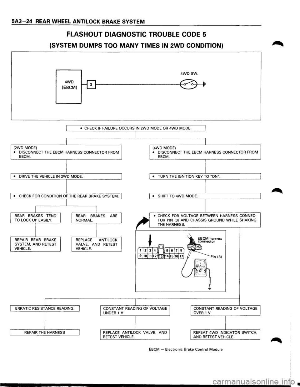
5A3-24 REAR WHEEL ANTILOCK BRAKE SYSTEM
FLASHOUT DIAGNOSTIC TROUBLE CODE 5
(SYSTEM DUMPS TOO MANY TIMES IN 2WD CONDITION)
4WD
(EBCM)
4WDSW.
I•
I • CHECK IF FAILURE OCCURS IN 2WD MODE OR 4WD MODE. I
I I (2WD MODE) (4WD MODE)
• DISCONNECT THE EBCM HARNESS CONNECTOR FROM • DISCONNECT THE EBCM HARNESS CONNECTOR FROM
EBCM. EBCM.
J I • DRIVE THE VEHICLE IN 2WD MODE. • TURN
THE IGNITION KEY TO "ON".
l I • CHECK FOR CONDITION OF THE REAR BRAKE SYSTEM. • SHIFT TO 4WD MODE.
I
I I I REAR BRAKES TEND REAR BRAKES ARE
~
• CHECK FOR VOLTAGE BETWEEN HARNESS CONNEC-
TO LOCK UP EASILY. NORMAL. TOR PIN (3) AND CHASSIS GROUND WHILE SHAKING
I I
THE HARNESS.
~ 1S
REPAIR REAR BRAKE REPLACE
ANTI LOCK EBCM harness
connector
SYSTEM, AND RETEST VALVE, AND
RETEST ·'"·. ~)l VEHICLE. VEHICLE. [1l21314l~ 5161718) .......
J9J1oJ11J12r13 14J15J1sJ 11] = Pin (3)
~-~\
~ -~~~
"!!'
ERRATIC RESISTANCE READING. I I CONSTANT READING OF VOLTAGE I I CONSTANT
READING OF VOLTAGE
UNDER 1 V OVER 1 V
REPAIR THE HARNESS I I REPLACE ANTILOCK VALVE, AND I I REPEAT 4WD INDICATOR
SWITCH, RETEST VEHICLE. AND RETEST VEHICLE.
EBCM
~ Electronic Brake Control Module
I
•
Page 407 of 1928
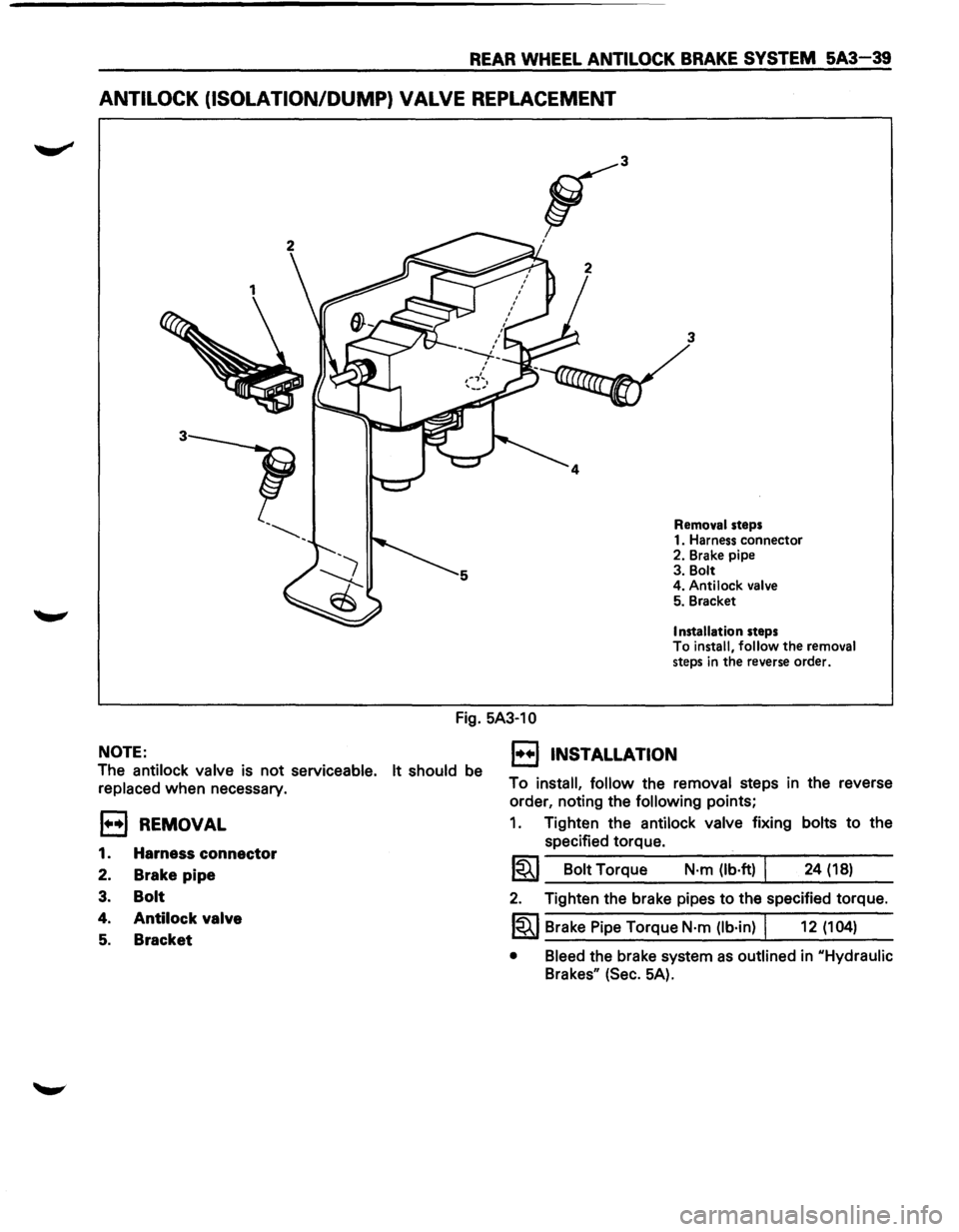
REAR WHEEL ANTILOCK BRAKE SYSTEM 5A3-39
ANTILOCK (ISOLATION/DUMP) VALVE REPLACEMENT
3
Removal steps
1. Harness connector
2. Brake pipe
3. Bolt
4. Antilock
valve 5. Bracket
Installation steps
To install, follow the removal
steps in the reverse order.
Fig. 5A3-10
NOTE:
The antilock valve is not serviceable. It should be
replaced when necessary.
EJ REMOVAL
1. Harness connector
2. Brake pipe
3. Bolt
4. Antilock valve
5. Bracket
1••1 INSTALLATION
To install, follow the removal steps in the reverse
order, noting the
following points;
1. Tighten the antilock valve fixing bolts to the
specified torque.
1~1 Bolt Torque N·m (lb·ft) I 24 (18)
2. Tighten the brake pipes to the specified torque.
1~1 Brake Pipe Torque N·m (lb·in) I 12 (104)
• Bleed the brake system as outlined in uHydraulic
Brakesu (Sec. 5A).
Page 413 of 1928
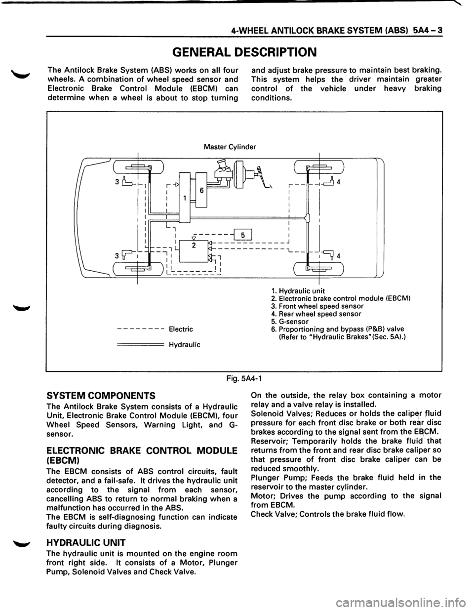
4-WHEEL ANTILOCK BRAKE SYSTEM (ABS) 5A4-3
GENERAL DESCRIPTION
The Antilock Brake System (ASS) works on all four
wheels. A combination of wheel speed sensor and
Electronic Brake Control Module (EBCM) can
determine
when a wheel is about to stop turning
and adjust brake pressure to maintain best braking.
This system
helps the driver maintain greater
control of the vehicle under heavy braking
conditions.
Master Cylinder
I I I I
--------Electric
===== Hydraulic
,--1 I
I
I
-ld4
1. Hydraulic unit 2. Electronic brake control module (EBCM)
3. Front wheel speed sensor 4. Rear wheel speed sensor
5. G-sensor 6. Proportioning and bypass (P&Bl valve
(Refer to "Hydraulic Brakes"(Sec. 5A).)
Fig. 5A4-1
SYSTEM COMPONENTS
The Antilock Brake System consists of a Hydraulic
Unit, Electronic Brake Control Module (EBCM), four
Wheel Speed Sensors, Warning Light, and G
sensor.
ELECTRONIC BRAKE CONTROL MODULE
(EBCM)
The EBCM consists of ABS control circuits, fault
detector, and a fail-safe. It drives the hydraulic unit
according to the signal from each sensor,
cancelling ABS to return to normal braking when a
malfunction has occurred in the ABS.
The EBCM is self-diagnosing function can indicate
faulty circuits during diagnosis.
'--" HYDRAULIC UNIT
The hydraulic unit is mounted on the engine room
front right side. It consists of a Motor, Plunger
Pump, Solenoid Valves and Check Valve. On
the
outside, the relay box containing a motor
relay and a valve relay is installed.
Solenoid Valves;
Reduces or holds the calip~r fluid
pressure for each front disc brake or both rear disc
brakes according
to the signal sent from the EBCM.
Reservoir;
Temporarily holds the brake fluid that
returns from the front and rear disc brake caliper so
that pressure of front disc brake caliper can be
reduced
smoothly.
Plunger
Pump; Feeds the brake fluid held in the
reservoir
to the master cylinder.
Motor; Drives the pump according to the signal
from EBCM.
Check
Valve; Controls the brake fluid flow.
Page 414 of 1928
5A4-4 4-WHEEL ANTILOCK BRAKE SYSTEM (ABS)
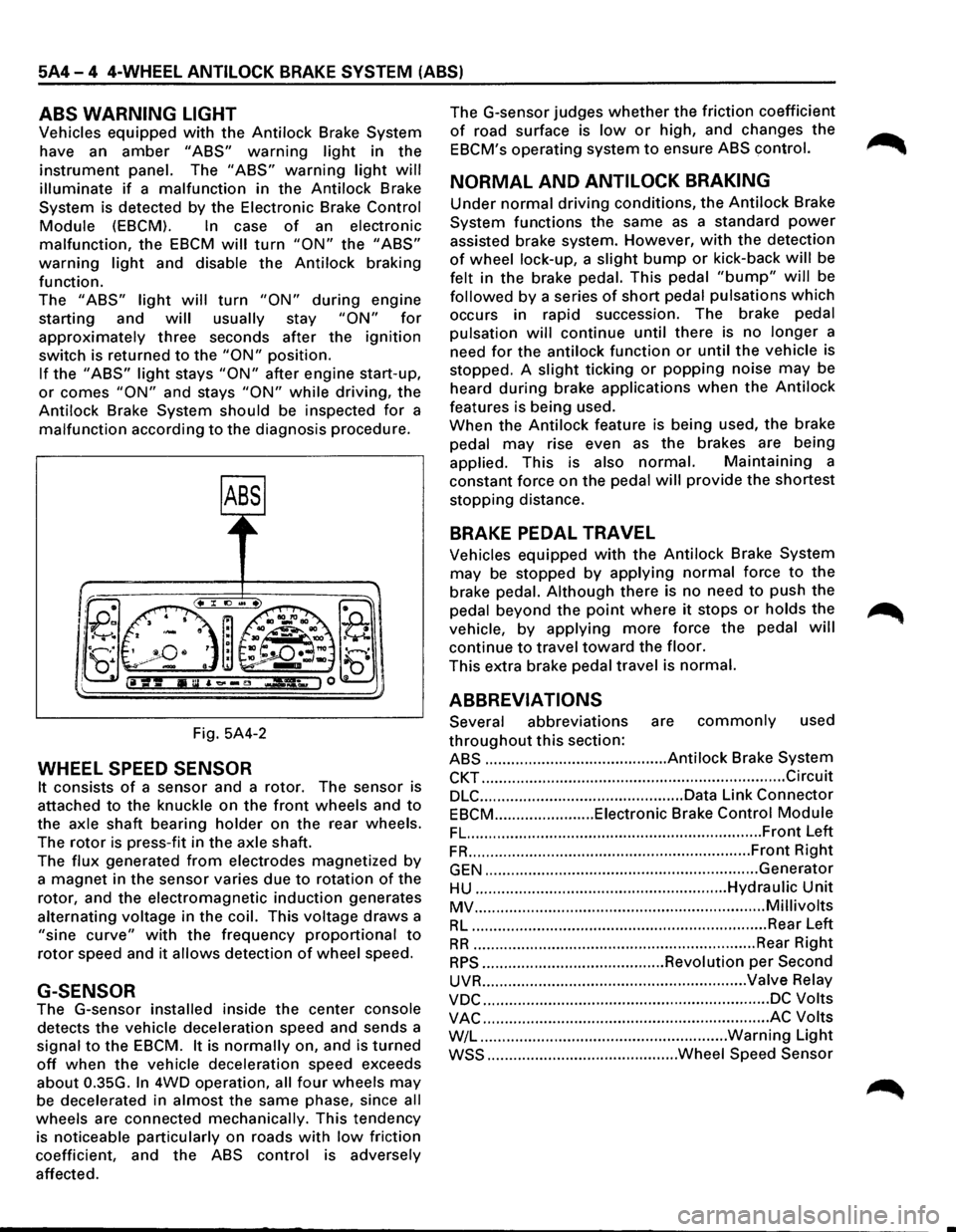
ABS WARNING LIGHT
Vehicles equipped with the Antilock Brake System
have an
amber "ABS" warning light in the
instrument panel. The "ABS" warning light will
illuminate if a malfunction in the Antilock Brake
System is detected by the Electronic Brake
Control
Module (EBCM). In case of an electronic
malfunction, the EBCM will turn "ON" the "ABS"
warning light and disable the Antilock braking
function.
The
"ABS" light will turn "ON" during engine
starting and
will usually stay "ON" for
approximately three seconds after the ignition
switch is returned to the "ON" position.
If the "ABS" light stays "ON" after engine start-up,
or comes "ON" and stays "ON" while driving, the
Antilock Brake System should be inspected
for a
malfunction according to the diagnosis procedure.
Fig. 5A4-2
WHEEL SPEED SENSOR
It consists of a sensor and a rotor. The sensor is
attached
to the knuckle on the front wheels and to
the axle shaft bearing holder on the rear wheels.
The
rotor is press-fit in the axle shaft.
The
flux generated from electrodes magnetized by
a magnet in the sensor varies due to rotation of the
rotor, and the electromagnetic
induction generates
alternating voltage in
the coil. This voltage draws a
"sine curve" with the frequency proportional to
rotor speed and it allows detection of wheel speed.
G-SENSOR
The G-sensor installed inside the center console
detects the vehicle deceleration speed and sends a
signal
to the EBCM. It is normally on, and is turned
off when the vehicle deceleration speed exceeds
about 0.35G.
In 4WD operation, all four wheels may
be decelerated in almost the same phase, since all
wheels are connected mechanically. This tendency
is noticeable particularly on roads
with low friction
coefficient, and the
ABS control is adversely
affected. The
G-sensor judges
whether the friction coefficient
of road surface is low or high, and changes the
EBCM's operating system to ensure ABS control.
NORMAL AND ANTILOCK BRAKING
Under normal driving conditions, the Antilock Brake
System functions the same
as a standard power
assisted brake system. However, with the detection
of wheel lock-up, a slight bump or kick-back will be
felt in the brake pedal. This pedal
"bump" will be
followed by a series of short pedal pulsations which
occurs in rapid succession. The brake pedal
pulsation
will continue until there is no longer a
need
for the antilock function or until the vehicle is
stopped. A
slight ticking or popping noise may be
heard
during brake applications when the Antilock
features is being used.
When the
Antilock feature is being used, the brake
pedal
may rise even as the brakes are being
applied. This is also
normal. Maintaining a
constant force on the pedal
will provide the shortest
stopping distance.
BRAKE PEDAL TRAVEL
Vehicles equipped with the Antilock Brake System
may be stopped by applying normal force to the
brake pedal.
Although there is no need to push the
pedal beyond the
point where it stops or holds the ~
vehicle, by applying more force the pedal will
continue to travel toward the floor.
This extra brake pedal travel is normal.
ABBREVIATIONS
Several abbreviations are commonly used
throughout this section:
ABS .......................................... Antilock Brake System
CKT ...................................................................... Circuit
DLC ............................................... Data Link Connector
EBCM ....................... Eiectronic Brake Control Module
FL. ................................................................... Front Left
FR ................................................................. Front Right
GEN ............................................................... Generator
HU .......................................................... Hydraulic Unit
MV ................................................................... Millivolts
RL .................................................................... Rear Left
RR ................................................................. Rear Right
RPS .......................................... Revolution per Second
UVR ............................................................. Valve Relay
VDC .................................................................. DC Volts
VAC .................................................................. AC Volts
W/L .........................................................
Warning Light
WSS ............................................ Wheel Speed Sensor
Page 431 of 1928
4-WHEEL ANTILOCK BRAKE SYSTEM (ABS) 5A4-21
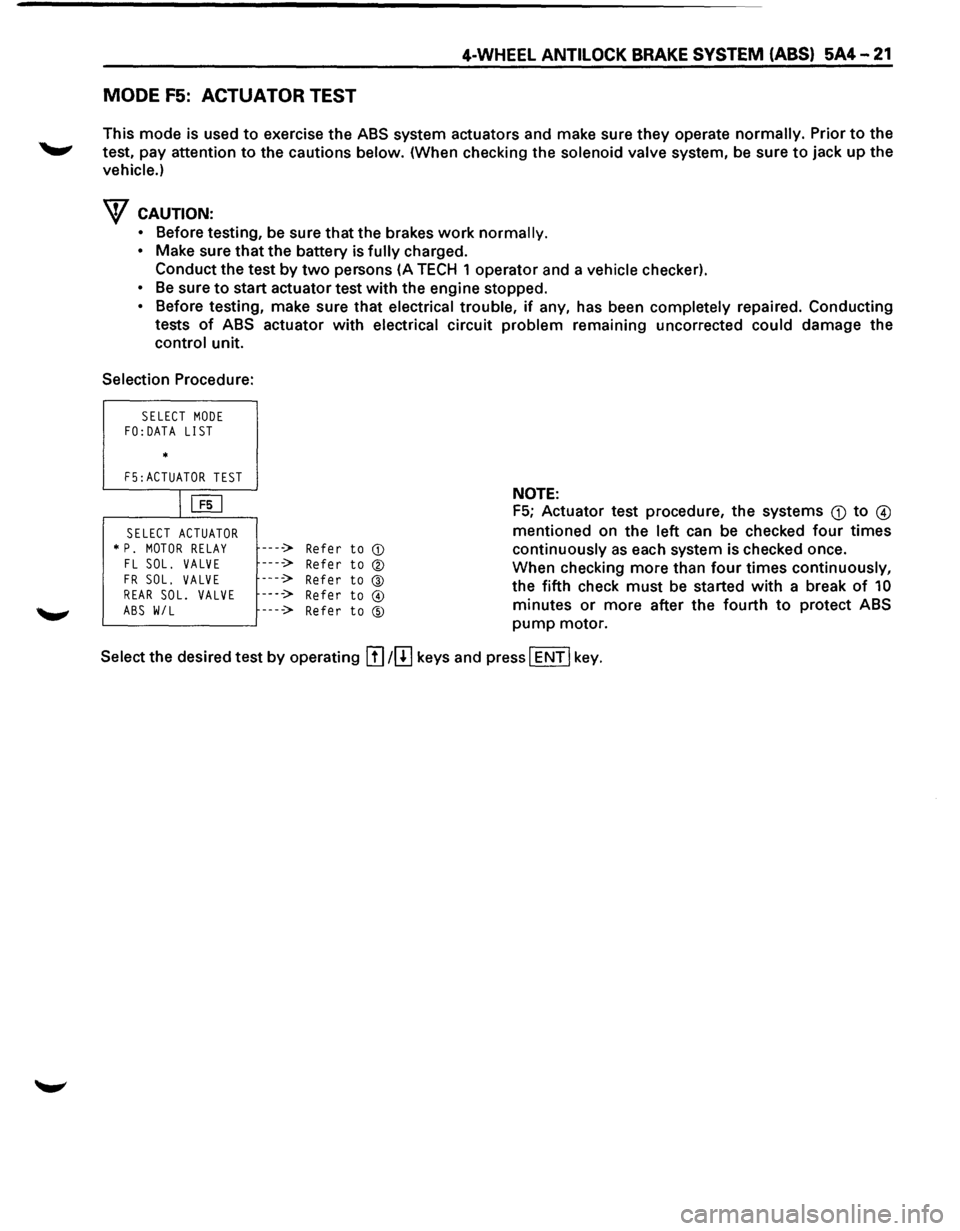
MODE F5: ACTUATOR TEST
This mode is used to exercise the ABS system actuators and make sure they operate normally. Prior to the
test, pay attention
to the cautions below. (When checking the solenoid valve system, be sure to jack up the
vehicle.)
w CAUTION:
• Before testing, be sure that the brakes work normally.
• Make sure that the battery is fully charged.
Conduct the test
by two persons (A TECH 1 operator and a vehicle checker).
• Be sure to start actuator test with the engine stopped.
• Before testing, make sure that electrical trouble, if any, has been completely repaired. Conducting
tests
of ABS actuator with electrical circuit problem remaining uncorrected could damage the
control unit.
Selection Procedure:
SELECT MODE FO:DATA LIST
*
F5:ACTUATOR TEST
IUiJ
SELECT ACTUATOR * P. MOTOR RELAY FL SOL. VALVE
FR SOL. VALVE REAR SOL. VALVE
ABS W/L
----> Refer to CD
----> Refer to ®
----> Refer to @ ----> Refer to @
----> Refer to ®
NOTE:
F5; Actuator test procedure, the systems Q) to @
mentioned on the left can be checked four times
continuously as each system is checked once.
When checking more than
four times continuously,
the fifth check
must be started with a break of 10
minutes or more after the fourth to protect ABS
pump motor.
Select the desired test
by operating !I] 1[!] keys and press I ENT I key.
Page 433 of 1928
4-WHEEL ANTILOCK BRAKE SYSTEM (ABS) 5A4-23
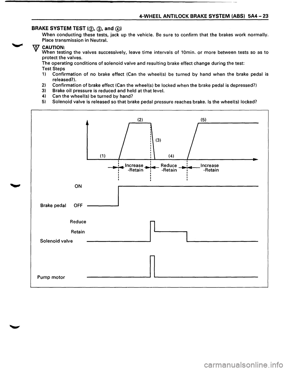
BRAKE
SYSTEM TEST (®, @, and @)
When conducting these tests, jack up the vehicle. Be sure to confirm that the brakes work normally.
Place transmission
in Neutral.
\V CAUTION: When testing the valves successively, leave time intervals of 10min. or more between tests so as to
protect the valves.
The operating conditions
of solenoid valve and resulting brake effect change during the test:
Test
Steps
1) Confirmation of no brake effect (Can the wheel(s) be turned by hand when the brake pedal is
released?).
2) Confirmation of brake effect (Can the wheel(s) be locked when the brake pedal is depressed?)
3) Brake oil pressure is reduced and held at that level.
4) Can the wheel(s) be turned by hand?
5) Solenoid valve is released so that brake pedal pressure reaches brake. Is the wheel(s) locked?
(2) (5)
I
(3)
(1) (4) I
I
..,. ;.,.. lncrea~e ..,.1.,.. Reduce I Increase ... : ... 1 -Retam 1 -Retain I -Retain I I I
I I I
I I I
I I I
ON
Brake
pedal OFF
Reduce
r
Retain
I Solenoid valve
Pump
motor ~
Page 442 of 1928
5A4-32 4-WHEEL ANTI LOCK BRAKE SYSTEM (ABS)
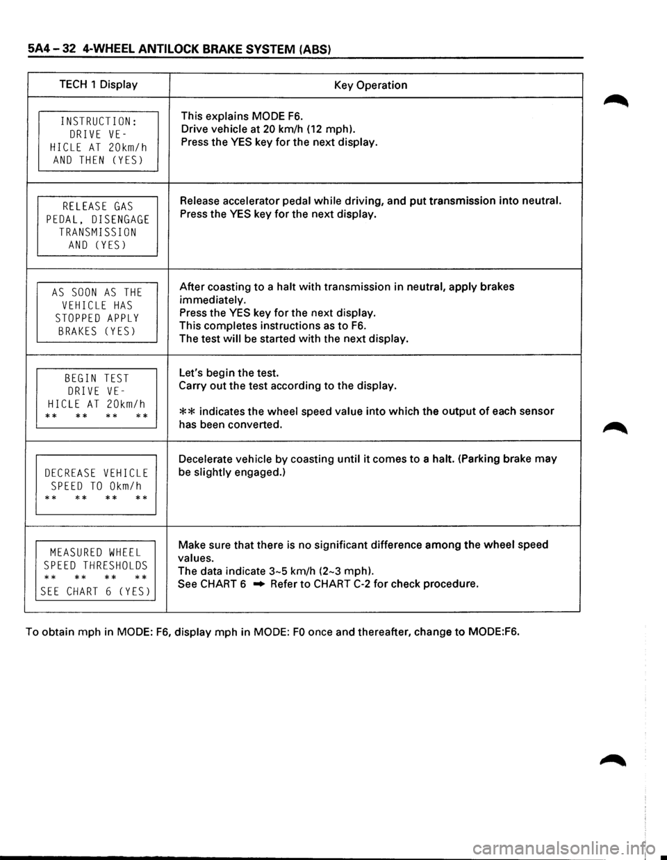
TECH 1 Display Key Operation
INSTRUCT I ON: This explains MODE F6.
DRIVE VE-Drive vehicle at 20 km/h (12 mph).
HICLE AT 20km/h Press the YES key for the next display.
AND THEN (YES)
RELEASE GAS Release accelerator pedal while driving, and put transmission into neutral.
PEDAL, DISENGAGE Press the YES key for the next display.
TRANSMISSION
AND (YES)
AS SOON AS THE After coasting to a halt with transmission in neutral, apply brakes
VEHICLE HAS immediately.
STOPPED APPLY Press the YES key for the next display.
BRAKES (YES) This completes instructions as to F6.
The test will be started with the next display.
BEGIN TEST Let's begin the test.
DRIVE VE-Carry out the test according to the display.
HICLE AT 20km/h ** indicates the wheel speed value into which the output of each sensor ** ** ** ** has been converted.
Decelerate vehicle by coasting until it comes to a halt. (Parking brake may
DECREASE VEHICLE be slightly engaged.)
SPEED TO Okm/h
** ** ** **
MEASURED WHEEL Make sure that there is no significant difference among the wheel speed
SPEED THRESHOLDS values.
** **
** ** The
data indicate 3-5 km/h (2-3 mph).
SEE CHART 6 (YES) See CHART 6 .. Refer to CHART C-2 for check procedure.
To obtain mph in
MODE: F6, display mph in MODE: FO once and thereafter, change to MODE:F6.
Page 483 of 1928
4-WHEEL ANTILOCK BRAKE SYSTEM (ABS) 5A4-73
ON-VEHICLE SERVICE
W CAUTION:
~ Replace all components included in repair kits used to service this system. Lubricate rubber parts with
clean, fresh brake fluid to ease assembly. Do not use shop air with in-line lubricators on brake parts,
as
damage to rubber components may result. If any hydraulic component is removed or brake line
disconnected,
it may be necessary to bleed part or all of the brake system.
NOTE:
The use of rubber hoses or parts other than those furnished specifically for the Anti lock Brake System may
lead to functional problems requiring major overhaul.
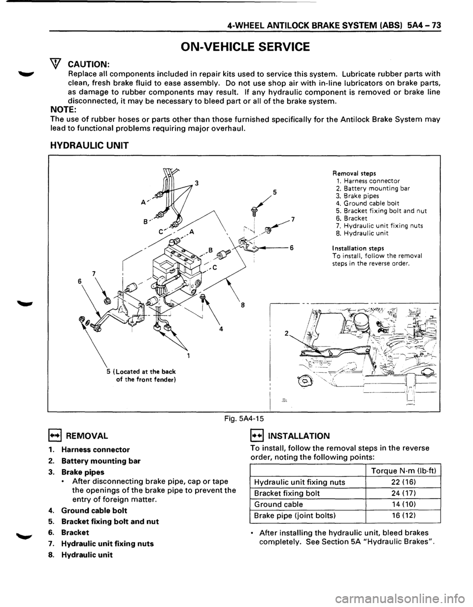
HYDRAULIC UNIT
5 (Located at the back
of the front fender) Removal
steps
1. Harness connector 2. Battery mounting bar 3. Brake pipes 4. Ground cable bolt 5. Bracket fixing bolt and nut 6. Bracket 7. Hydraulic unit fixing nuts 8. Hydraulic unit
Installation steps To install, follow the removal
steps in the reverse order.
1••1 REMOVAL
Fig. 5A4-15
I••IINSTALLATION
1. Harness connector
2. Battery mounting bar
3. Brake pipes
• After disconnecting brake pipe, cap or tape
the
openings of the brake pipe to prevent the
entry of foreign matter.
4. Ground cable bolt
5. Bracket fixing bolt and nut
6. Bracket
7. Hydraulic unit fixing nuts
8. Hydraulic unit
To install, follow the removal steps in the reverse
order,
noting the following points:
Torque
N·m Ob·ftl
Hydraulic unit fixing nuts 22 (16)
Bracket fixing bolt 24 (17)
Ground cable 14 (10)
Brake pipe (joint bolts) 16 (12)
• After installing the hydraulic unit, bleed brakes
completely.
See Section 5A "Hydraulic Brakes".
Page 491 of 1928
PARKING BRAKES 5C-1
SECTION 5C
PARKING BRAKES
'\f7 CAUTION:
Yf All brake attaching fasteners are an important attaching part in that they could affect performance of vital
parts and systems, and/or could result in major repair expense. They must be replaced with one ofthe same
part number
or with and equivalent part if replacement becomes necessary. Do not use replacement parts of
lesser quality or substitute design. Torque values must be used as specified during reassembly to assure
proper retention
of these parts.
CONTENTS
General Description ..................... 5C-1
Operation . . . . . . . . . . . . . . . . . . . . . . . . . . . . . 5C-2
On-Vehicle Service
..................... 5C-3
Parking Brake Lever Replacement . .
. . . . .
5C-3
Parking Brake Front Cable . .
. . . . . . . . . . .
5C-4
Parking Brake Rear Cable . .
. . . . . . . . . . . .
5C-5
Parking Brake Lining Inspection ......... 5C-6
Parking Brake Rotor (Drum) Inspection ... 5C-6
Parking Brake Adjustment .............. 5C-7
Main Data and Specifications ............. 5C-8
General
Specifications ................. 5C-8
Torque Specifications ................. 5C-8
GENERAL DESCRIPTION
Pulling up the parking brake lever by hand will set the
parking brake.
Once pulled up, the lever is held by a
ratchet type
lock until it is released. The position of the
lever is transmitted through cable/lever systems to the
rear
wheels. These parts are designed to obtain
sufficient braking force
when parking on slopes. When
the parking brake is set,
or when the ignition SW is in
the
"ON" position, the brake warning light illuminates.
The rear wheel parking brake is a duo-servo brake
(mechanical inside expansion type) built in to the rear
disc brake. Parking brake adjustment is made through
the adjusting
hole (bored through back plate). Parking
brake
lever stroke should be adjusted to 6 or 7
notches. Refer
to "Parking Brake Adjustment" in
this Section.