steering ISUZU TROOPER 1995 Workshop Manual
[x] Cancel search | Manufacturer: ISUZU, Model Year: 1995, Model line: TROOPER, Model: ISUZU TROOPER 1995Pages: 1928
Page 803 of 1928
New or service sensors will already have the
compound
applied to the threads. If a sensor is
removed
from an engine and iffor any reason it
is to be reinstalled, the threads must have anti
seize compound
applied before reinstallation.
•
Apply anti-seize compound or equivalent to
threads of oxygen sensor if necessary.
• Tighten the oxygen sensor to the specified
torque.
1~1 Torque N·m (lb·ft) 55 (40)
1. H02S wiring connector
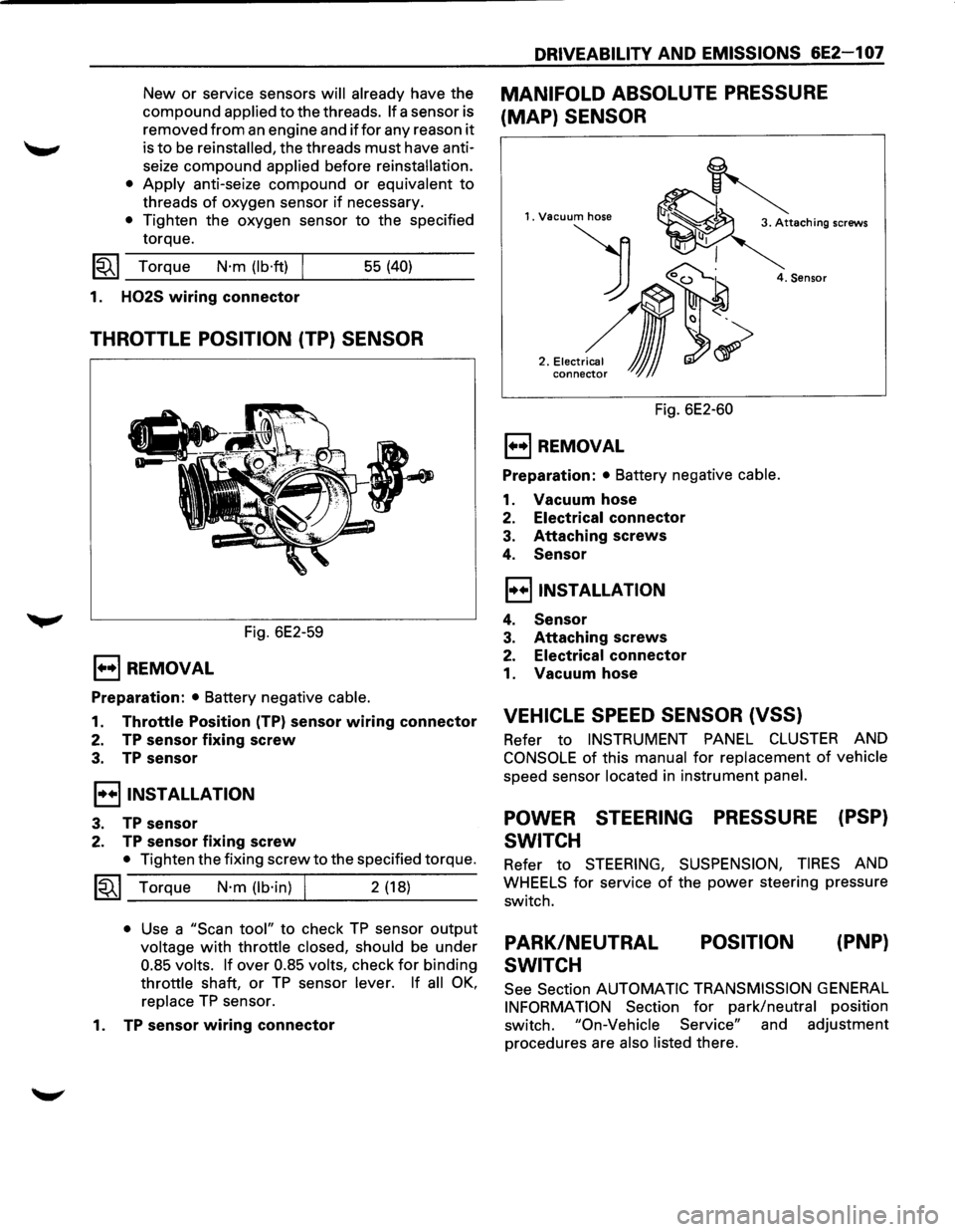
THROTTLE POSITION (TP) SENSOR
Fig. 6E2-59
E) REMOVAL
Preparation: • Battery negative cable.
1. Throttle Position (TP) sensor wiring connector
2. TP sensor fixing screw
3. TP sensor
I••IINSTALLATION
3. TP sensor
2. TP sensor fixing screw
• Tighten the fixing screw to the specified torque.
~~~ Torque N·m (lb·in) I 2 (18)
• Use a "Scan tool" to check TP sensor output
voltage with throttle closed, should be under
0.85 volts. If over 0.85 volts, check for binding
throttle shaft, or TP sensor lever. If all OK,
replace TP sensor.
1.
TP sensor wiring connector
DRIVEABILITY AND EMISSIONS 6E2-1 07
MANIFOLD ABSOLUTE PRESSURE
(MAP) SENSOR
1. Vacuum hose
) 0~
2 .• ,.~,,~,~
conne~ JJJ
4. Sensor
Fig. 6E2-60
E) REMOVAL
Preparation: • Battery negative cable.
1. Vacuum hose
2. Electrical connector
3. Attaching screws
4. Sensor
I••IINSTALLATION
4. Sensor
3. Attaching screws
2. Electrical connector
1. Vacuum hose
VEHICLE SPEED SENSOR (VSS)
Refer to INSTRUMENT PANEL CLUSTER AND
CONSOLE of this manual for replacement of vehicle
speed sensor located in instrument panel.
POWER STEERING PRESSURE (PSP)
SWITCH
Refer to STEERING, SUSPENSION, TIRES AND
WHEELS for service of the power steering pressure
switch.
PARK/NEUTRAL
SWITCH POSITION
(PNP}
See
Section AUTOMATIC TRANSMISSION GENERAL
INFORMATION Section for park/neutral position
switch.
"On-Vehicle Service" and adjustment
procedures are
also listed there.
Page 808 of 1928
6E2-112 DRIVEABILITY AND EMISSIONS
CHART C-1E
POWER STEERING PRESSURE (PSP) SWITCH DIAGNOSIS
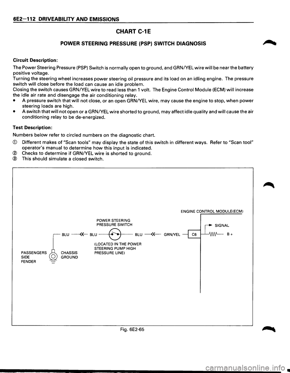
Circuit Description:
The Power Steering Pressure
(PSP) Switch is normally open to ground, and GRNIYEL wire will be near the battery
positive
voltage.
Turning the steering wheel increases power steering oil pressure and its load on an idling engine. The pressure
switch
will close before the load can cause an idle problem.
Closing
the switch causes GRN/YEL wire to read less than 1 volt. The Engine Control Module (ECM) will increase
the
idle air rate and disengage the air conditioning relay.
•
A pressure switch that will not close, or an open GRNIYEL wire, may cause the engine to stop, when power
steering loads are high.
• A switch that will not open or a GRNIYEL wire shorted to ground, may affect idle quality and will cause the air
conditioning
relay to be de-energized.
Test Description:
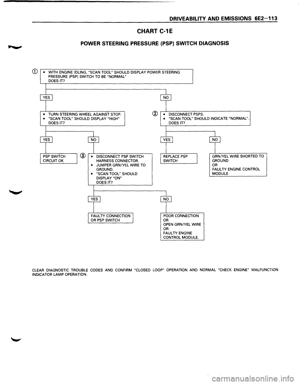
Numbers
below refer to circled numbers on the diagnostic chart.
CD Different makes of "Scan tools" may display the state of this switch in different ways. Refer to "Scan tool"
operator's manual to determine how this input is indicated.
® Checks to determine if GRNIYEL wire is shorted to ground.
@ This should simulate a closed switch.
POWER STEERING PRESSURE SWITCH ENGINE
CONTROL
MODULE(ECM)
I SIGNAL
r
BLU ---(~ BLU --+8 .. •f---BLU --{~ GRN/YEL ~ ~ B +
(LOCATED IN THE POWER
STEERING PUMP HIGH PASSENGERS CHASSIS PRESSURE LINE)
SIDE GROUND
FENDER
Fig. 6E2-65
•
Page 809 of 1928
DRIVEABILITY AND EMISSIONS 6E2-113
CHART C-1E
POWER STEERING PRESSUR,.E (PSP) SWITCH DIAGNOSIS
CD • WITH ENGINE IDLING, "SCAN TOOL" SHOULD DISPLAY POWER STEERING PRESSURE (PSP) SWITCH TO BE "NORMAL" DOES IT?
•
TURN STEERING WHEEL AGAINST STOP. ® • DISCONNECT PSPS. • "SCAN TOOL" SHOULD DISPLAY "HIGH"
DOES IT? • "SCAN TOOL" SHOULD INDICATE "NORMAL".
@ • DISCONNECT PSP SWITCH HARNESS CONNECTOR.
• JUMPER GRNIYEL WIRE TO GROUND. • "SCAN TOOL" SHOULD DISPLAY "ON" DOES IT? DOES
IT?
POOR CONNECTION OR OPEN GRN/YEL WIRE OR FAULTY ENGINE
CONTROL MODULE. GRN/YEL
WIRE SHORTED TO GROUND OR FAULTY ENGINE
CONTROL MODULE
CLEAR
DIAGNOSTIC TROUBLE CODES AND CONFIRM "CLOSED LOOP" OPERATION AND NORMAL "CHECK ENGINE" MALFUNCTION
INDICATOR LAMP OPERATION.
Page 823 of 1928
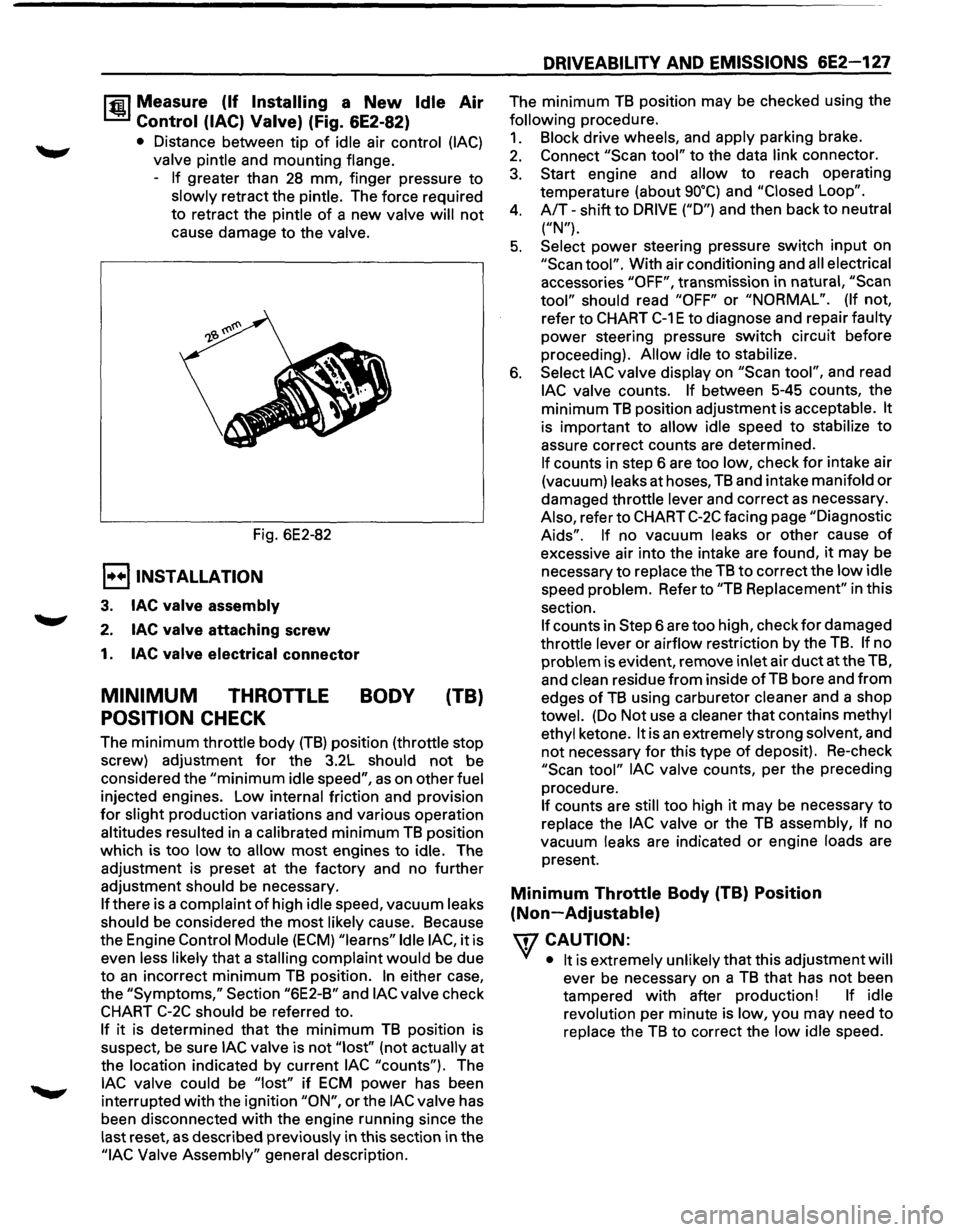
1~1 Measure (If Installing a New Idle Air
Control (lAC) Valve) (Fig. 6E2-82)
• Distance between tip of idle air control (lAC)
valve pintle and mounting flange.
-
If greater than 28 mm, finger pressure to
slowly retract the pintle. The force required
to retract the pintle
of a new valve will not
cause damage to the valve.
Fig. 6E2-82
E) INSTALLATION
3. lAC valve assembly
2. lAC valve attaching screw
1. lAC valve electrical connector
MINIMUM THROTTLE BODY (TB)
POSITION CHECK
The minimum throttle body (TB) position (throttle stop
screw) adjustment
for the 3.2L should not be
considered the
"minimum idle speed", as on other fuel
injected engines. Low internal friction and provision
for slight production variations and various operation
altitudes resulted in a calibrated
minimum TB position
which is too
low to allow most engines to idle. The
adjustment is preset at the factory and no further
adjustment should be necessary.
If there is a complaint of high idle speed, vacuum leaks
should be considered the
most likely cause. Because
the Engine
Control Module (ECM) "learns" Idle lAC, it is
even less likely
that a stalling complaint would be due
to
an incorrect minimum TB position. In either case,
the
"Symptoms," Section "6E2-B" and lAC valve check
CHART C-2C should be referred to.
If it is determined that the minimum TB position is
suspect,
be sure lAC valve is not "lost'' (not actually at
the location indicated by current
lAC "counts"). The
lAC valve could be "lost" if ECM power has been
interrupted
with the ignition "ON", or the lAC valve has
been disconnected
with the engine running since the
last reset,
as described previously in this section in the
"lAC Valve Assembly" general description.
DRIVEABILITY AND EMISSIONS 6E2-127
The minimum TB position may be checked using the
following procedure.
1. Block drive wheels, and apply parking brake.
2. Connect "Scan tool" to the data link connector.
3. Start engine and allow to reach operating
temperature (about
go•q and "Closed Loop".
4. A/T-shift to DRIVE ("D") and then back to neutral
("N").
5. Select power steering pressure switch input on
"Scan tool". With air conditioning and all electrical
accessories
"OFF", transmission in natural, "Scan
tool" should read "OFF" or "NORMAL". (If not,
refer to
CHART C-1 E to diagnose and repair faulty
power steering pressure switch circuit before
proceeding).
Allow idle to stabilize.
6. Select lAC valve display on "Scan tool", and read
lAC valve counts. If between 5-45 counts, the
minimum
TB position adjustment is acceptable. It
is important to allow idle speed to stabilize to
assure correct counts are determined.
If counts in step 6 are too low, check for intake air
(vacuum) leaks at hoses,
TB and intake manifold or
damaged throttle lever and correct as necessary.
Also, refer to
CHART C-2C facing page "Diagnostic
Aids". If no vacuum leaks or other cause of
excessive air into the intake are found, it may be
necessary
to replace the TB to correct the low idle
speed problem. Refer to
"TB Replacement" in this
section.
If counts in Step 6 are too high, check for damaged
throttle lever or airflow restriction by the
TB. If no
problem is evident, remove inlet air
duct at the TB,
and
clean residue from inside of TB bore and from
edges of TB using carburetor cleaner and a shop
towel. (Do Not use a cleaner that contains methyl
ethyl ketone.
It is an extremely strong solvent, and
not necessary for this type of deposit). Re-check
"Scan tool" lAC valve counts, per the preceding
procedure.
If counts are still too high it may be necessary to
replace the
lAC valve or the TB assembly, If no
vacuum leaks are indicated
or engine loads are
present.
Minimum Throttle Body (TB) Position
(Non-Adjustable)
\fl CAUTION:
VI • It is extremely unlikely that this adjustment will
ever be necessary on a TB that has not been
tampered
with after production! If idle
revolution per minute is low, you may need
to
replace the TB to correct the low idle speed.
Page 857 of 1928
DRIVEABILITV AND EMISSIONS 6E2-161
SECTION C-1 0
AIR CONDITIONING (A/C) COMPRESSOR CLUTCH CONTROL
SYSTEM
CONTENTS
General Description ..................... 6E2-161 On-Vehicle Service ...................... 6E2-161
Operation ........................... 6E2-161 Chart C-10 Air Conditioning (A/C) System
Diagnosis ............................. 6E2-161 Functional Check ...................... 6E2-162
GENERAL DESCRIPTION
OPERATION
This system consists of a high pressure cut-out switch,
Air Conditioning (A/C) compressor
relay, A/C thermo
switch relay, A/C controller and the compressor.
The high pressure cut-out switch
(normally closed),
opens when the head pressure gets too high. This will
disable
the A/C clutch, before damage can occur to the
compressor or other
A/C components.
When
A/C control switch is "ON" and the high pressure
switch and thermo switch are
closed, a request signal
is sent to the Engine Control Module (ECM). The ECM
will then energize the A/C clutch through the A/C
clutch relay. The A/C controller which is separate from
the ECM will then turn the A/C cooling fan "ON".
The A/C controller controls the A/C cooling fan, as well
as sending a signal to the ECM on model equipped with
automatic transmission.
The
ECM will disable the A/C clutch during Wide Open
Throttle,
or high power steering loads. The ECM has a
slight delay for clutch engagement to allow for the idle
to slightly increase. Refer to CHART C-1 0 for wiring and
circuit description.
DIAGNOSIS
Chart C-10 should be used for the electrical portion of
the A/C circuit. Section 1 B should be used for
diagnosing the refrigerant portion of the system. The
"Scan tool" will be used in diagnosing the system, as it
has the ability to read the A/C request inputto the ECM,
as well as displaying when the ECM has commanded
the
A/C clutch "ON".
ON-VEHICLE SERVICE
For removal and replacement of A/C components,
refer to
A/C (SECTION 1 B) in this Manual.
Page 1029 of 1928
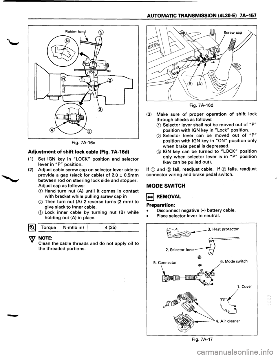
Rubber band
Fig. 7A-16c
Adjustment of shift lock cable (Fig. 7A-16d)
(1) Set IGN key in "LOCK" position and selector
lever
in "P" position.
(2)
Adjust cable screw cap on selector lever side to
provide a gap (slack for cable) of 2.0 ± O.Smm
between rod on steering lock side and stopper.
Adjust cap as follows:
CD Hand turn nut (A) until it comes in contact
with bracket while pulling screw cap in
® Then turn nut (A) 2 reverse turns (2 mm) to
give slack to inner cable.
@ Lock inner cable by turning nut (8) while
holding nut (A) in place.
~~~ Torque N-m(lb-in) j 4 (35)
W NOTE:
Clean the cable threads and do not apply oil to
the threaded portions.
AUTOMATIC TRANSMISSION (4L30·E) 7A-157
Fig. 7A-16d
(3) Make sure of proper operation of shift lock
through checks as follows:
CD Selector lever shall not be moved out of "P"
position with IGN key in "Lock" position.
® Selector lever can be moved out of "P"
position with IGN key in "ON" position only
when brake pedal is depressed.
@ IGN key can be turned to "LOCK" position
only when selector lever is in "P" position
(key can be
pulled out).
If CD and @ fail, readjust cable. If ® fails, readjust
connector
wiring and brake pedal switch.
MODE SWITCH
1++1 REMOVAL
Preparation:
• Disconnect negative (-) battery cable.
• Place selector lever
in neutral.
~3. Heat protector
2. Selector lever
6. Mode switch
1. Cover
~
Fig. 7A-17
Page 1219 of 1928
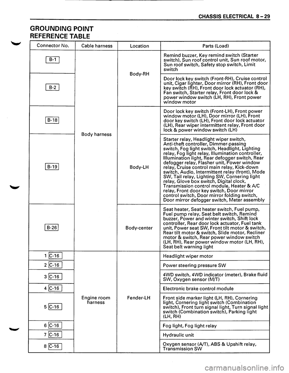
GROUNDING POINT
REFERENCE TABLE
Connector No.
Cable harness
~
~
I B-1a1
Body harness
I B-191
I B-261
1 lc-16 I
2IC-16 I
3IC-16 I
4IC-16 I
Engine room
5IC-16 I
harness
6IC-16 I
7IC-16 I
aiC-16 1
Location
Body-RH
Body-LH
Body-center
Fender-LH
CHASSIS ElECTRICAL 8-29
Parts (Load)
Remind buzzer, Key remind switch (Starter
switch),
Sun roof control unit, Sun roof motor, Sun roof switch, Safety stop switch, Limit
switch
Door lock key switch (Front-RH), Cruise control
unit, Cigar lighter, Door mirror (RH), Front door
key switch (RH), Front door lock actuator (RH),
Fan switch, Starter relay, Front
door lock & power window switch (LH, RH), Front power window motor
Door lock key switch (Front-LH), Front power window motor (LH), Door mirror (LH), Front
door key switch (LH), Front door lock actuator
(LH), Rear wiper intermittent relay, Front door
lock & power window switch (LH)
Starter relay, Headlight
wiper switch,
Anti-theft controller,
Dimmer·passing switch, Fog light switch, Headlight, Lighting
relay, Fog
light relay, Illumination controller,
Illumination light, Rear defogger switch, Rear
defogger relay, Flasher unit,
Power window relay, Cruise control main relay, Kick-down
switch, Audio, Intermittent relay (front), Mode SW, Tail relay, Lighting SW, Cornering light
relay, Glove box switch, Digital clock,
Transmission control module, Heater & A/C
relay, Front
door key switch, Door mirror
control switch, Door mirror folding switch,
Door mirror defogger switch, Meter assembly
Seat heater, Seat heater switch, Fuel pump, Fuel pump relay, Seat belt switch, Remind
buzzer, Power and winter switch, Shift lock
controller, Rear
door lock actuator, Fuel tank
unit, Power seat SW, Front tilt motor & switch,
Rear tilt motor & switch, Slide motor, Recliner
motor & switch, Rear power window switch
(LH, RH), Rear power window motor (LH, RH),
Seat belt warning light
Headlight
wiper motor
Power steering pressure SW
4WD switch, 4WD indicator (meter), Brake fluid
SW, Oxygen sensor (M/T)
Electronic brake control
module
Front side marker light (LH, RH), Cornering
light, Cornering light switch (Combination
switch), Front turn signal light, Turn signal light switch (Combination switch), Parking light (LH, RH)
Fog light, Fog light relay
Hydraulic
unit
Oxygen sensor (AfT), ABS & Upshift relay,
Transmission SW
Page 1234 of 1928
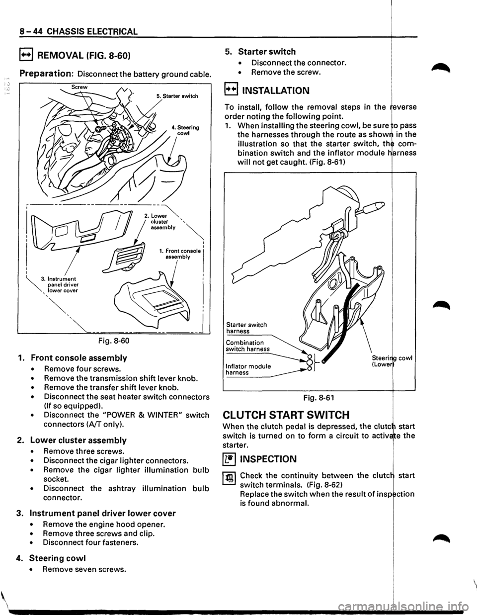
8-44 CHASSIS ELECTRICAL
B REMOVAL (FIG. 8-60)
Preparation: Disconnect the battery ground cable.
5. Starter switch
Fig. 8-60
1. Front console assembly
• Remove four screws.
• Remove the transmission shift lever knob.
• Remove the transfer shift lever knob.
• Disconnect the seat heater switch connectors
(If so equipped).
• Disconnect the "POWER & WINTER" switch
connectors
(A/T only).
2. Lower cluster assembly
• Remove three screws.
• Disconnect the cigar lighter connectors.
• Remove the cigar lighter illumination bulb
socket.
• Disconnect the ashtray illumination bulb
connector.
3. Instrument panel driver lower cover
• Remove the engine hood opener.
• Remove three screws and clip.
• Disconnect four fasteners.
4. Steering cowl
• Remove seven screws .
5. Starter switch
• Disconnect the connector.
• Remove the screw.
B INSTALLATION
To install, follow the removal steps in the everse
order noting the
following point.
1. When installing the steering cowl, be sure o pass
the harnesses through the route as
show in the
illustration so that the starter switch, th com
bination switch and the inflator
module
will not get caught. (Fig. 8-61)
Starter switch
harness
Fig. 8-61
CLUTCH START SWITCH
cowl
When the clutch pedal is depressed, the clute start
switch is turned on
to form a circuit to activ e the
starter.
~ INSPECTION
1 til!. I Check the continuity between the clute start
switch terminals. (Fig. 8-62)
Replace the switch when the result
of insp ction
is found abnormal.
'
Page 1239 of 1928
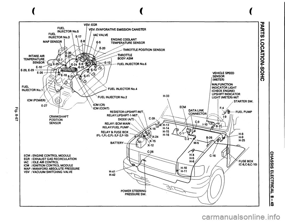
!! (Q
(
FUEL INJECTOR
No.1
/
FUEL INJECTOR
No.5
FUEL INJECTOR
No.3
I
\/.
ICM
CPOWERl
_/
E-27
cp
I
CRANKSHAFT
~
POSITION SENSOR
ECM
: ENGINE
CONTROL
MODULE
EGR
:EXHAUST
GAS
RECIRCULATION
lAC
: IDLE
AIR
CONTROL
ICM
: IGNmON
CONTROL
MODULE
MAP
: MAN
I FORD
ABSOLUTE
PRESSURE
VSV
:VACUUM
SWITCHING
VALVE
(
VSV:EGR I VSV:
EVAPORATIVE
EMISSION
CANISTER
THROTTLE
POSmON
SENSOR
~FUEL
INJECTOR
No.6
FUEL
INJECTOR
No.4
FUEL
INJECTOR
No.2
ICMCCRl ICMCCONTl
RESISTOR:UPSHIFT-MIT RELAY:UPSHIFT-1-MIT
DIODECAITl
RELAY:
ECM
MAIN
RELAY:FUEL
PUMP
RELAY
& FUSE
BOX
CFL-1,FL-2,FL-3,F-2,F-10l
H-41 H-42
POWER
STEERING
PRESSURE
SW.
H-33
VEHICLE
SPEED
SENSOR (METER) MALFUNCTION INDICATOR
LIGHT
(CHECK
ENGINE)
UPSHIFT
INDICATOR
LIGHT
CMETERl-MfT
(
/STARTER
SW.
F-4
/
DATA
LINK
I
d .
'v_AR__
FUEL
PUMP
CONNECTOR~
!P
~;~·
/~
,,
1-9
~ ~ r-0 n ~ 0 2 • en 0 X n
(") ::::1: )> CJ)
CJ) Cii m rm ~ :D ~ r-01) I fD
Page 1259 of 1928
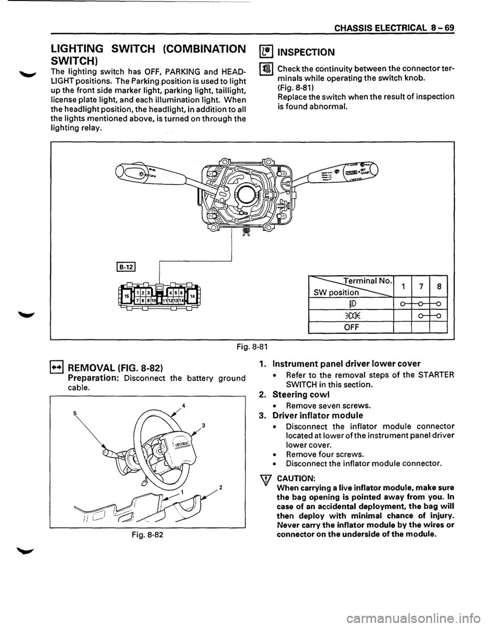
LIGHTING SWITCH (COMBINATION
SWITCH)
The lighting switch has OFF, PARKING and HEAD
LIGHT positions. The Parking position is used to light
up the front side marker light, parking light, taillight,
license
plate light, and each illumination light. When
the headlight position, the headlight, in addition
to all
the lights mentioned above, is turned on through the
lighting relay.
CHASSIS ELECTRICAL 8-69
~ INSPECTION
I til Check the continuity between the connector ter
minals
while operating the switch knob.
(Fig. 8-81)
Replace the switch when the result
of inspection
is found abnormal.
Terminal No.
SW position 1 7 8
~D
OFF
Fig. 8-81
B REMOVAL (FIG. 8-82)
Preparation: Disconnect the battery ground
cable.
4
2
Fig. 8-82 1.
Instrument panel driver lower cover
• Refer to the
removal steps of the STARTER
SWITCH
in this section.
2.
Steering cowl
• Remove seven screws.
3.
Driver inflator module
• Disconnect the inflator module connector
located at lower
oft he instrument panel driver
lower cover.
• Remove four screws.
• Disconnect the inflator module connector.
W CAUTION:
When carrying a live inflator module. make sure
the bag opening is pointed away from you. In
case of an accidental deployment, the bag will
then deploy with minimal chance of injury.
Never carry
the inflator module by the wires or
connector on the underside of the module.