light JAGUAR X308 1998 2.G Owners Manual
[x] Cancel search | Manufacturer: JAGUAR, Model Year: 1998, Model line: X308, Model: JAGUAR X308 1998 2.GPages: 2490, PDF Size: 69.81 MB
Page 1922 of 2490

Exterior Lighting - Exterior Lighting
Diagnosis and Testing
Tests Using the Portable Diagnostic Unit
Refer to PDU User Guide
The complexity of the electronics involved with the various Electronic Control Modules and the multiplexed communication
networks, preclude the use of workshop general electrical test equipment. Therefore, reference should be made to the PDU
User Guide for detailed inst ructions on testing the exterior lamps and circuits.
The PDU systematically tests and analyses the lamp assemblies, the bulbs and the electrical connections to them. It should
be noted that the lamps are not wired direct ly to the switches. Actuation of a switch provides an input signal to the Body
Processor which interpre ts the signal as a request to switch output from the Bo dy Processor, either directly or indirectly to a
specific lamp.
Where a fault involving a lamp is indicated by the PDU, befo re replacing the component, some basic diagnostic methods
may be necessary to confirm that connections are good and that wiring is not damaged.
Page 1923 of 2490
Exterior Lighting - Brake Pedal Position (BPP) Switch
Removal and Installation
Removal
Installation
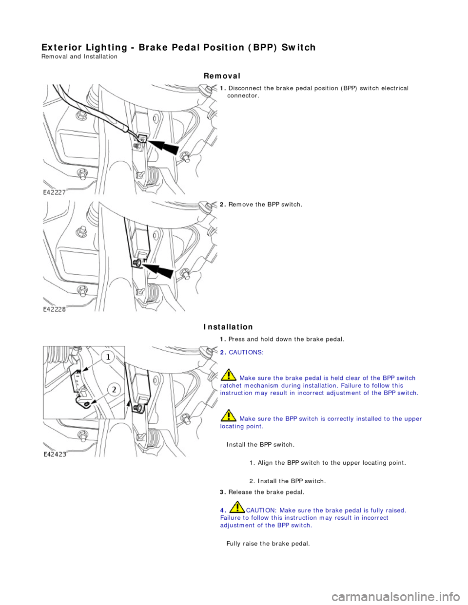
1. Disconnect the brake pedal posi tion (BPP) switch electrical
connector.
2. Remove the BPP switch.
1. Press and hold down the brake pedal.
2. CAUTIONS:
Make sure the brake pedal is held clear of the BPP switch
ratchet mechanism during installation. Failure to follow this
instruction may result in incorrect adjustment of the BPP switch.
Make sure the BPP sw itch is correctly installed to the upper
locating point.
Install the BPP switch. 1. Align the BPP switch to the upper locating point.
2. Install the BPP switch.
3. Release the brake pedal.
4. CAUTION: Make sure the br ake pedal is fully raised.
Failure to follow this instru ction may result in incorrect
adjustment of the BPP switch.
Fully raise the brake pedal.
Page 1925 of 2490
Exterior Lighting - Fog Lamp Switch
Removal and Installation
Removal
Installation
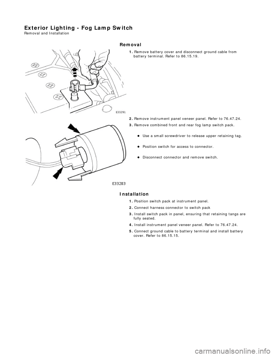
1. Remove battery cover and disc onnect ground cable from
battery terminal. Refer to 86.15.19.
2. Remove instrument pa nel veneer panel. Refer to 76.47.24.
3. Remove combined front and rear fog lamp switch pack.
Use a small screwdriver to re lease upper retaining tag.
Position switch for access to connector.
Disconnect connector and remove switch.
1. Position switch pack at instrument panel.
2. Connect harness connector to switch pack
3. Install switch pack in panel, ensuring that retaining tangs are
fully seated.
4. Install instrument panel veneer panel. Refer to 76.47.24.
5. Connect ground cable to batter y terminal and install battery
cover. Refer to 86.15.15.
Page 1926 of 2490
Exterior Lighting - Front Fog Lamp
Removal and Installation
Removal
Installation
1.
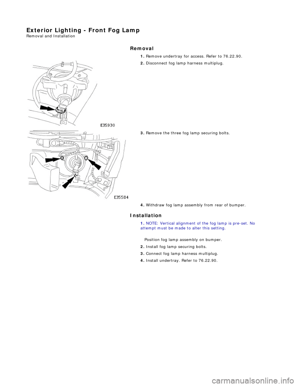
Remove undertray for ac cess. Refer to 76.22.90.
2. Disconnect fog lamp harness multiplug.
3. Remove the three fog la mp securing bolts.
4. Withdraw fog lamp assembly from rear of bumper.
1. NOTE: Vertical alignment of the fog lamp is pre-set. No
attempt must be made to alter this setting.
Position fog lamp assembly on bumper.
2. Install fog lamp securing bolts.
3. Connect fog lamp harness multiplug.
4. Install undertray. Refer to 76.22.90.
Page 1927 of 2490
Exterior Lighting - Front Fog Lamp Bulb
Removal and Installation
Removal
Installation
1.
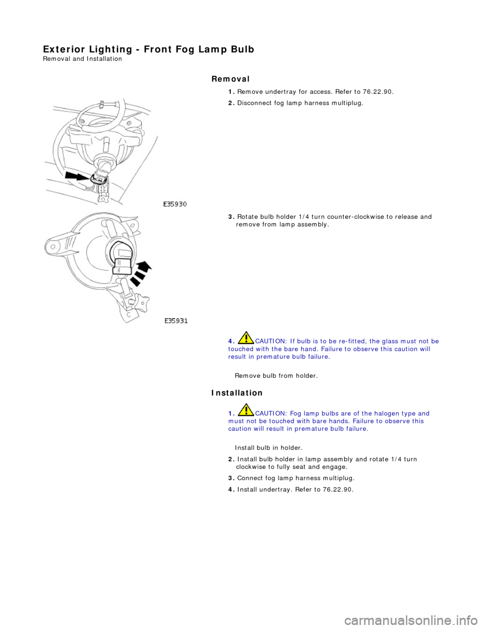
Remove undertray for ac cess. Refer to 76.22.90.
2. Disconnect fog lamp harness multiplug.
3. Rotate bulb holder 1/4 turn counter-clockwise to release and
remove from lamp assembly.
4. CAUTION: If bulb is to be re -fitted, the glass must not be
touched with the bare hand. Failure to observe this caution will
result in premature bulb failure.
Remove bulb from holder.
1. CAUTION: Fog lamp bulbs are of the halogen type and
must not be touched with bare hands. Failure to observe this
caution will result in premature bulb failure.
Install bulb in holder.
2. Install bulb holder in lamp assembly and rotate 1/4 turn
clockwise to fully seat and engage.
3. Connect fog lamp harness multiplug.
4. Install undertray. Refer to 76.22.90.
Page 1928 of 2490
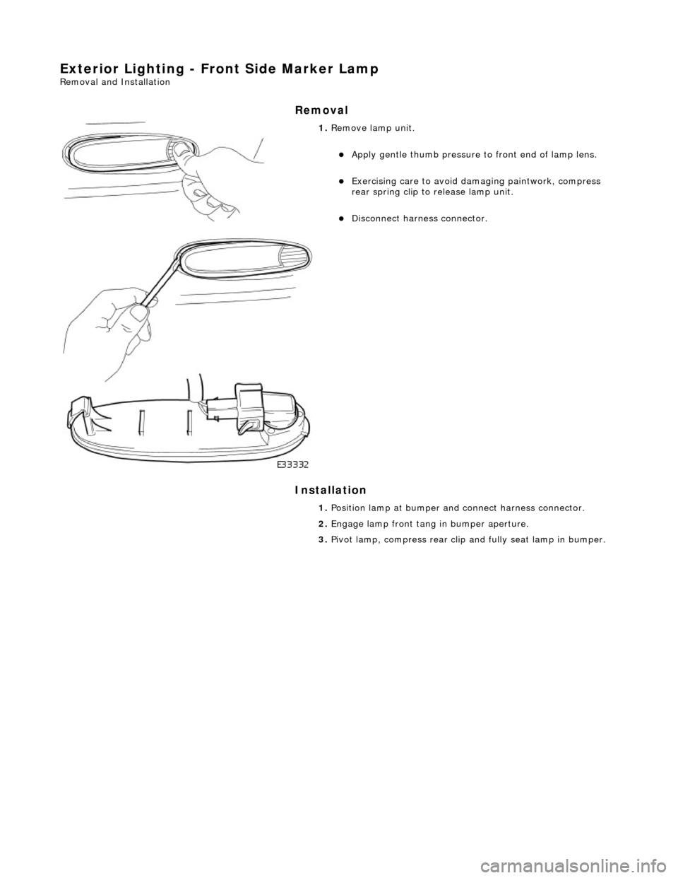
Exterior Lighting - Front Side Marker Lamp
Removal and Installation
Removal
Installation
1. Remove lamp unit.
Apply gentle thumb pressure to front end of lamp lens.
Exercising care to avoid damaging paintwork, compress
rear spring clip to release lamp unit.
Disconnect harness connector.
1. Position lamp at bumper an d connect harness connector.
2. Engage lamp front tang in bumper aperture.
3. Pivot lamp, compress rear clip and fully seat lamp in bumper.
Page 1929 of 2490

Exterior Lighting - Front Side Marker Lamp Bulb
Removal and Installation
Removal
1. Applying firm hand pressure to front end, pivot lamp assembly
for access to rear end.
2. Exercising care to avoid dama ging paintwork, use a small
screwdriver at rear end of lamp, to press and release retaining
tang.
3. Withdraw lamp from bumper for access and disconnect harness multiplug.
4. Rotate bulb holder 1/4 turn counter-clockwise to release it
from lamp assembly.
5. Withdraw bulb from holder.
Page 1931 of 2490

Exterior Lighting - Front Turn Signal Lamp Bulb
Removal and Installation
Removal
1. Applying firm hand pressure to inner end, pivot indicator lamp
assembly for access to outer end.
2. Exercising care to avoid dama ging paintwork, use a small
screwdriver at outer end of lamp, to press and release retaining clip.
3. Withdraw lamp from bumper for access and disconnect harness multiplug.
4. Rotate bulb holder 1/8 turn to release it from lamp assembly.
5. Withdraw bulb holder and remove bulb.
Page 1933 of 2490

Exterior Lighting - Headlamp Assembly
Removal and Installation
Removal
1. Remove radiator grill. Refer to 76.55.03.
2. Remove radiator grill surro und. Refer to 76.55.15.
3. Remove headlamp trim panel. Refer to 76.11.23.
4. Disconnect headlamp levelling actuator if fitted.
5. Disconnect headlamp assembly harness connector.
6. Remove headlamp assembly to body lower nuts.
7. Remove headlamp to body upper nuts.
Page 1936 of 2490

Exterior Lighting - Headlamp Leveling Motor
Removal and Installation
Removal
Installation
1. Disconnect harness multiplug from headlamp levelling
actuator.
2. Rotate actuator 1/4 turn inwards, tilt forward end downward
and withdraw assembly from headlamp.
1. With forward end tilted downward , position actuator assembly
on headlamp.
2. Align actuator with headlamp an d rotate it 1/4 turn outwards
to engage and fully seat.
3. Connect harness multiplug to actuator.
4. Carry out headlamp beam al ignment to the appropriate
alignment equipment instructions.