JAGUAR X308 1998 2.G Owners Manual
X308 1998 2.G
JAGUAR
JAGUAR
https://www.carmanualsonline.info/img/21/7640/w960_7640-0.png
JAGUAR X308 1998 2.G Owners Manual
Page 1867 of 2490
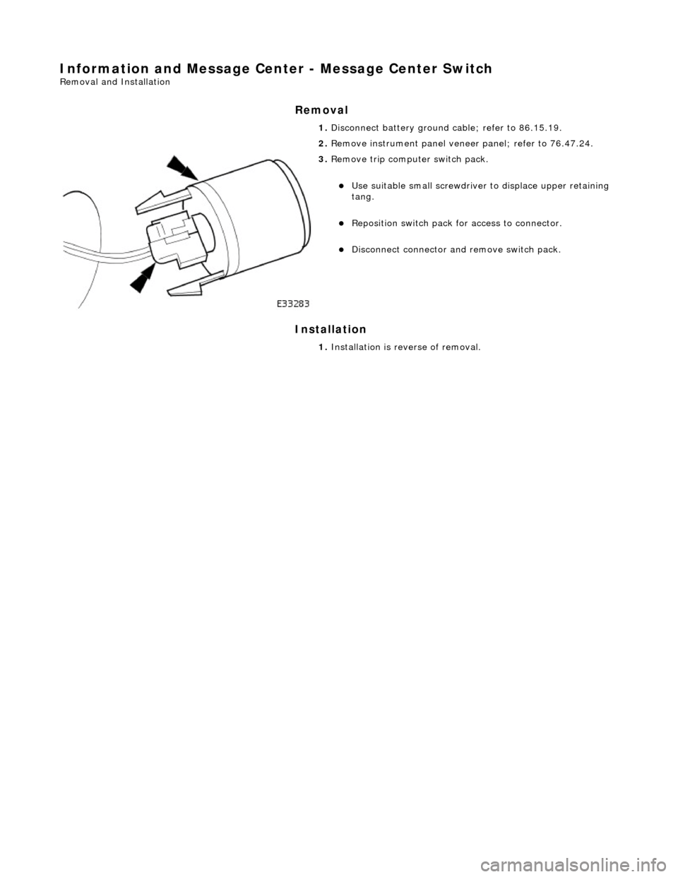
Information and Message Center - Message Center Switch
Removal and Installation
Removal
Installation
1.
Disconnect battery ground cable; refer to 86.15.19.
2. Remove instrument panel veneer panel; refer to 76.47.24.
3. Remove trip computer switch pack.
Use suitable small screwdriver to displace upper retaining
tang.
Reposition switch pack for access to connector.
Disconnect connector and remove switch pack.
1. Installation is reverse of removal.
Page 1871 of 2490
Parking Aid - Parking Aid Module
Removal and Installation
Removal
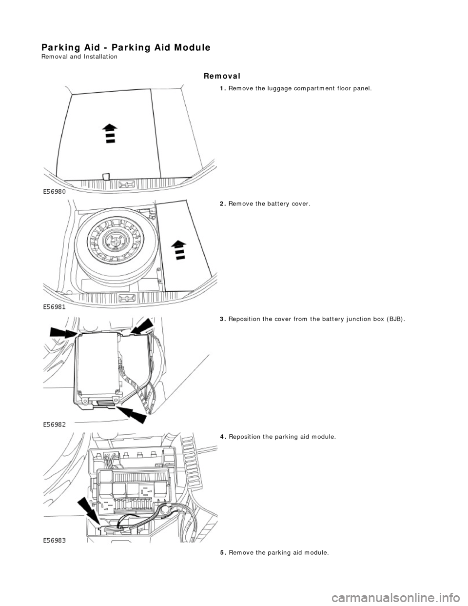
1. Remove the luggage compartment floor panel.
2. Remove the battery cover.
3. Reposition the cover from the battery junction box (BJB).
4. Reposition the parking aid module.
5. Remove the parking aid module.
Page 1878 of 2490
Battery, Mounting and Cables - Battery
Removal and Installation
Removal
Installation
1.
Remove the luggage compartment floor panel (when standard
size spare wheel is supplied) and the cover from the battery.
2. Disconnect the battery cables.
Disconnect the ground cable. Disconnect the positive cable.
1. Disconnect the vent pipe.
3. Remove the battery.
1. Remove the two bolts which secure the battery clamp.
2. Remove the clamp.
3. Remove the battery.
1. Installation is the reverse of removal.
2. Perform the Battery Reconnection Procedure described in this
section.
Page 1879 of 2490
Battery, Mounting and Cables - Battery Ground Cable
Removal and Installation
Removal
Installation
1.
Remove the luggage compartment floor panel (when standard
size spare wheel is supplied) and the cover from the battery.
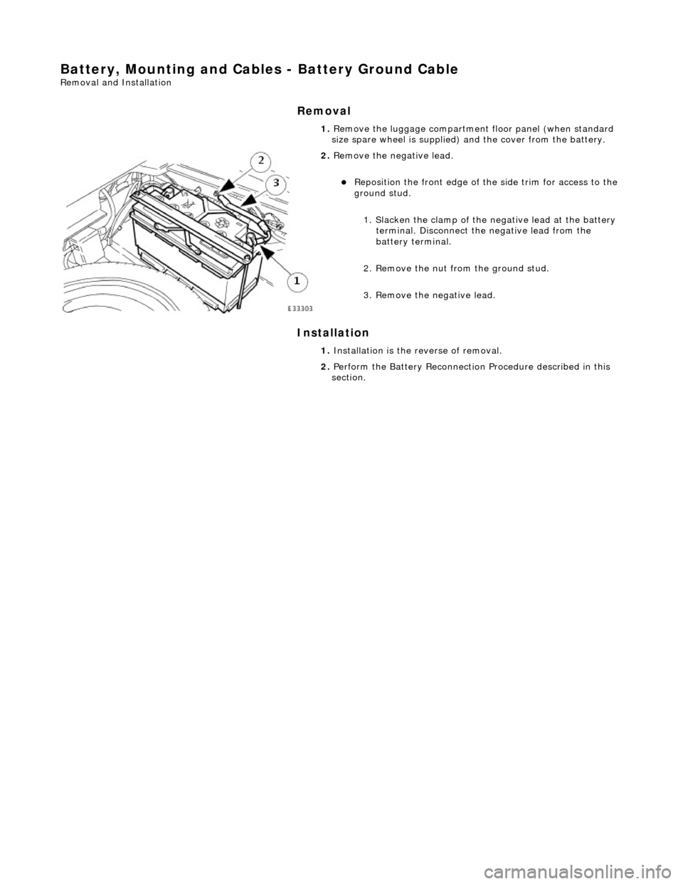
2. Remove the negative lead.
Reposition the front e dge of the side trim for access to the
ground stud.
1. Slacken the clamp of the ne gative lead at the battery
terminal. Disconnect the negative lead from the
battery terminal.
2. Remove the nut from the ground stud.
3. Remove the negative lead.
1. Installation is the reverse of removal.
2. Perform the Battery Reconnection Procedure described in this
section.
Page 1880 of 2490
Battery, Mounting and Cables - Battery Positive Cable
Removal and Installation
Removal
Installation
1.
Remove the luggage compartment floor panel (when standard
size spare wheel is supplied) and the cover from the battery.
2. Disconnect the positive lead.
1. Slacken the clamp of the po sitive lead at the battery
terminal. Disconnect the positive lead from the
battery terminal.
2. Remove the cover from th e high power protection
module for access to the positive supply stud.
3. Remove the positive lead.
1. Remove the nut from the positive supply stud.
2. Remove the positive lead.
1. Installation is the reverse of removal.
2. Perform the Battery Reconnection Procedure described in this
section.
Page 1881 of 2490
Battery, Mounting and Cables - Battery Retaining Bracket
Removal and Installation
Removal
Installation
1.
Remove the luggage compartment floor panel (when standard
size spare wheel is supplied) and the cover from the battery.
2. Disconnect the battery terminal ground cable.
3. Remove the battery hold-down clamp.
1. Remove the two bolts which secure the battery hold-down clamp.
2. Remove the hold-down clamp.
1. Installation is the reverse of removal.
2. Perform the Battery Reconnection Procedure described in this
section.
Page 1885 of 2490
If the field were not controlled, the 'B+' output would rise to a level which could damage bulbs and ECMs. The regulator
compares the output voltage to an intern al voltage reference circuit to achieve the controlled output of the generator.
Suppression Module
Although the output from the generator is fi nely controlled and relatively smooth, it is still a pulsed DC output at a varying
frequency proportional to engine speed.
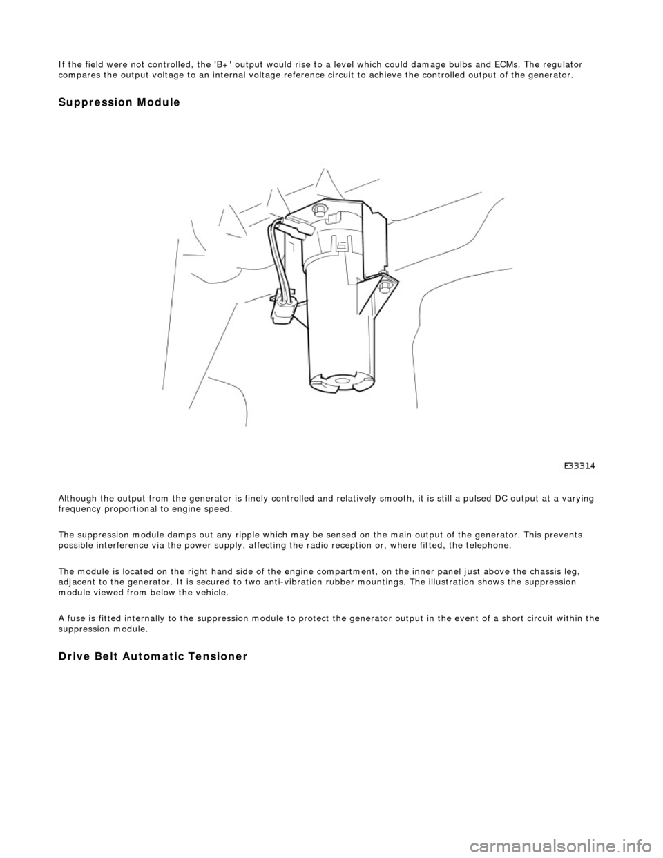
The suppression module damps ou t any ripple which may be sensed on the main output of the generator. This prevents
possible interference via the power supply, affecting the radio reception or, where fitted, the telephone.
The module is located on the right hand side of the engine compartment, on the inner panel just above the chassis leg,
adjacent to the generator. It is secured to two anti-vibration rubber moun tings. The illustration shows the suppression
module viewed from below the vehicle.
A fuse is fitted internally to the suppression module to protect the generator output in the event of a short circuit within th e
suppression module.
Drive Belt Automatic Tensioner
Page 1925 of 2490
Exterior Lighting - Fog Lamp Switch
Removal and Installation
Removal
Installation
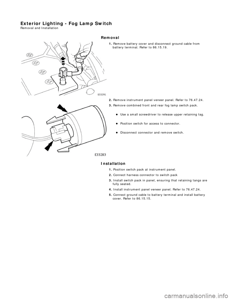
1. Remove battery cover and disc onnect ground cable from
battery terminal. Refer to 86.15.19.
2. Remove instrument pa nel veneer panel. Refer to 76.47.24.
3. Remove combined front and rear fog lamp switch pack.
Use a small screwdriver to re lease upper retaining tag.
Position switch for access to connector.
Disconnect connector and remove switch.
1. Position switch pack at instrument panel.
2. Connect harness connector to switch pack
3. Install switch pack in panel, ensuring that retaining tangs are
fully seated.
4. Install instrument panel veneer panel. Refer to 76.47.24.
5. Connect ground cable to batter y terminal and install battery
cover. Refer to 86.15.15.
Page 1933 of 2490
Exterior Lighting - Headlamp Assembly
Removal and Installation
Removal
1. Remove radiator grill. Refer to 76.55.03.
2. Remove radiator grill surro und. Refer to 76.55.15.
3. Remove headlamp trim panel. Refer to 76.11.23.
4. Disconnect headlamp levelling actuator if fitted.
5. Disconnect headlamp assembly harness connector.
6. Remove headlamp assembly to body lower nuts.
7. Remove headlamp to body upper nuts.
Page 1935 of 2490
5. Align headlamp beams.
6. Install headlamp trim panel. Refer to 76.11.23.
7. Install radiator grill surround. Refer to 76.55.15.
8. Install radiator gril l. Refer to 76.55.03.
