panel JAGUAR X308 1998 2.G Manual PDF
[x] Cancel search | Manufacturer: JAGUAR, Model Year: 1998, Model line: X308, Model: JAGUAR X308 1998 2.GPages: 2490, PDF Size: 69.81 MB
Page 1809 of 2490

10. Disconnect radiator bottom hose.
1. Release hose retaining clip.
2. Disconnect hose.
11. Disconnect radiator top hose.
1. Release hose retaining clip.
2. Disconnect hose.
12. Disconnect connector from pressure switch.
13. Release radiator top retaining panel.
Remove bolts.
Page 1810 of 2490

14. Disconnect compressor to condenser discharge line from
condenser.
1. Remove bolt.
2. Discard O-ring seal.
3. Install suitable blanking plugs.
15. Disconnect condenser to receiver / drier line from receiver /
drier.
1. Remove bolt.
2. Discard O-ring seal.
3. Install suitable blanking plugs.
16. Remove radiator retaining panel.
1. Remove panel.
2. Remove mounting bushes.
17. Disconnect hood switch harness connector.
Page 1811 of 2490
Installation
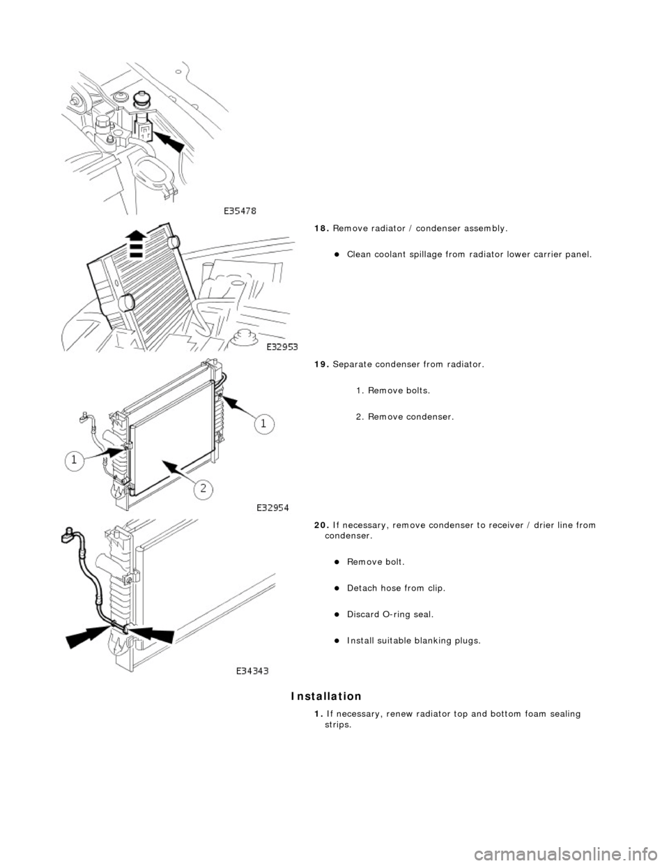
18. Remove radiator / condenser assembly.
Clean coolant spillage from radiator lower carrier panel.
19. Separate condenser from radiator.
1. Remove bolts.
2. Remove condenser.
20. If necessary, remove condenser to receiver / drier line from
condenser.
Remove bolt.
Detach hose from clip.
Discard O-ring seal.
Install suitable blanking plugs.
1. If necessary, renew radiator top and bottom foam sealing
strips.
Page 1814 of 2490

10. Connect radiator top hose to radiator.
1. Connect top hose.
2. Reposition and tighten hose clip.
11. Install radiator retaining panel.
Install bolts and sequenti ally tighten from center
outwards.
12. Connect radiator bottom hose to radiator.
1. Connect bottom hose.
2. Reposition and tighten hose clip.
13. Install twin fan and motor as sembly; refer to 26.25.12.
14. Connect pressure switch.
Page 1821 of 2490

Control Components - Control Components
Description and Operation
System Controls
The climate control system is controlled by : 1. 1. Manual input from the operator, via the center console located control panel.
2. 2. Automatically by means of the A/CCM.
Output is based upon input from the following devices:
Motorized In-car aspirator External air temperature sensor Coolant temperature sensor Heater 'air-off' (the temperature of the air leaving the matrix fins) temperature sensor Evaporator 'air-off' (the temperature of the air leaving the evaporator fins) temperature sensor Solar sensor Left hand blower recirculation / fresh air flap potentiometer Right hand blower recirculation / fresh air flap potentiometer Upper air distribution box (ADB) center and side face flap servomotor potentiometer ADB defrost flap servomotor potentiometer Air conditioning unit Foot flap servomotor potentiometer Air conditioning unit Cool Air Bypass flap servomotor potentiometer Thumbwheel controls on the facia vent assemblies which provide manu al adjustment of the airflow volume. Road and engine speed signals input to the A/CCM
Climate Control Panel
Communication between the control panel and the A/CCM is via a serial data communications link.
Switching the Climate Control system ON
The climate control system can be switched ON by pressing one of the following :
Ref #1 On / Off (resumes the system on in the previous settings).
Ref #10 A / C (resumes the system on in the previous settings).
Ref #11 AUTO (resumes the system on at the previous temperature setting).
Page 1827 of 2490

Maximum Cooling (temperature setting LO)
Air Conditioning Control Module (A/CCM)
Location
The A/CCM is located on the right hand side of the air conditioning unit and controls all system functions.
The temperature within the passenger compartment is continually compared with the temperature selected on the control
panel LCD. The A/CCM receives data input signals and compares these with signal s from the system temperature sensors
and feedback devices. Based on this information the A/CCM adjusts the air outlet temperatur e, airflow and distribution from
the air conditioning system in to the passenger compartment.
Identification
ItemControlOverride Allowed
Water valveFully closed (energised)-
BlowerMaximumYes
Fresh / recircRecirculationYes
Air distributionFace (state lamp OFF)Yes
A/C systemONYes
Cool air by-passFully open-
Page 1830 of 2490
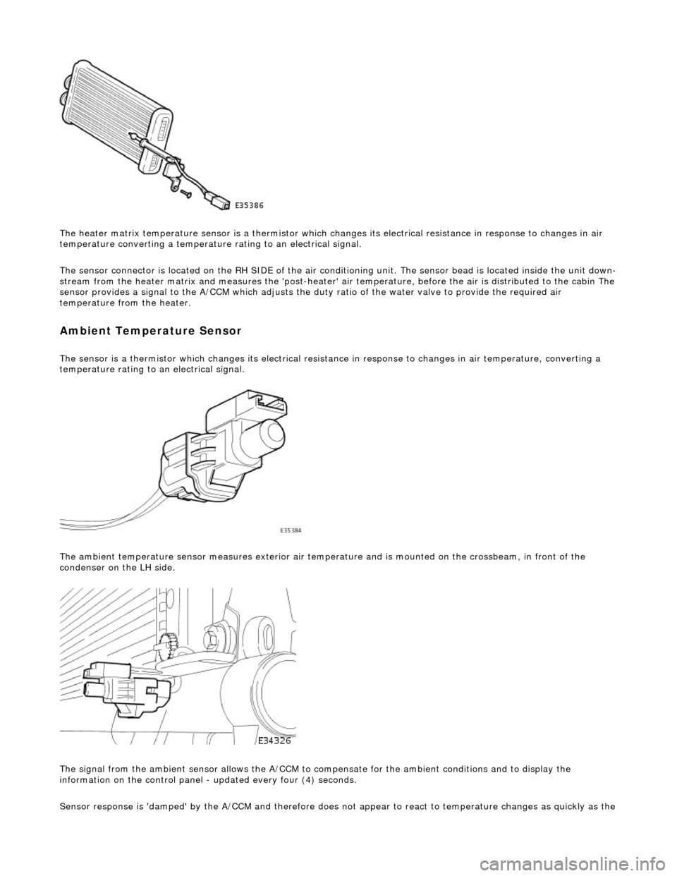
The heater matrix temperature sensor is a thermistor which changes its electrical resistance in response to changes in air
temperature converting a temperature rating to an electrical signal.
The sensor connector is located on the RH SIDE of the air conditioning unit. The sensor bead is located inside the unit down-
stream from the heater matrix and measures the 'post-heater' air temperature, before the air is distribu ted to the cabin The
sensor provides a signal to the A/CCM which adjusts the duty ratio of the water valve to provide the required air
temperature from the heater.
Ambient Temperature Sensor
The sensor is a thermistor which changes its electrical resistance in response to changes in air temperature, converting a
temperature rating to an electrical signal.
The ambient temperature sensor measures exterior air temper ature and is mounted on the crossbeam, in front of the
condenser on the LH side.
The signal from the ambient sensor allo ws the A/CCM to compensate for the ambient conditions and to display the
information on the control panel - updated every four (4) seconds.
Sensor response is 'damped' by the A/CCM and ther efore does not appear to react to temperature chan
ges as quickly as the
Page 1834 of 2490
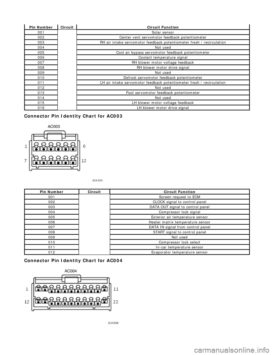
Connector Pin Identity Chart for AC003
Connector Pin Identity Chart for AC004
Pin NumberCircuitCircuit Function
001Solar sensor
002Center vent servomotor feedback potentiometer
003RH air intake servomotor feedback potentiometer fresh / recirculation
004Not used
005Cool air bypass servomotor feedback potentiometer
006Coolant temperature signal
007RH blower motor voltage feedback
008RH blower motor drive signal
009Not used
010Defrost servomotor feedback potentiometer
011LH air intake servomotor feedback potentiometer fresh / recirculation
012Not used
013Foot servomotor feedback potentiometer
014Not used
015LH blower motor voltage feedback
016LH blower motor drive signal
Pin NumberCircuitCircuit Function
001Screen request to ECM
002CLOCK signal to control panel
003DATA OUT signal to control panel
004Compressor lock signal
005Exterior air temperature sensor
006Heater matrix temperature sensor
007DATA IN signal from control panel
008START signal to control panel
009Not used
010Compressor lock select
011In-car temperature sensor
012Evaporator temperature sensor
Page 1835 of 2490
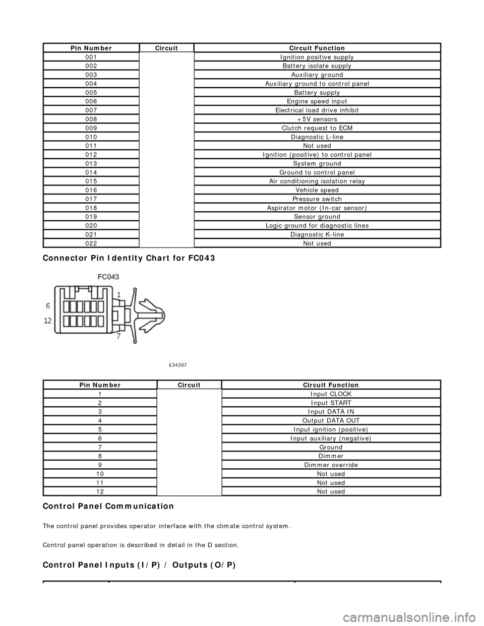
Connector Pin Identity Chart for FC043
Control Panel Communication
The control panel provides operator interface with the climate control system.
Control panel operation is described in detail in the D section.
Control Panel Inputs (I/P) / Outputs (O/P)
Pin NumberCircuitCircuit Function
001Ignition positive supply
002Battery isolate supply
003Auxiliary ground
004Auxiliary ground to control panel
005Battery supply
006Engine speed input
007Electrical load drive inhibit
008+5V sensors
009Clutch request to ECM
010Diagnostic L-line
011Not used
012Ignition (positive) to control panel
013System ground
014Ground to control panel
015Air conditioning isolation relay
016Vehicle speed
017Pressure switch
018Aspirator motor (In-car sensor)
019Sensor ground
020Logic ground for diagnostic lines
021Diagnostic K-line
022Not used
Pin NumberCircuitCircuit Function
1Input CLOCK
2Input START
3Input DATA IN
4Output DATA OUT
5Input ignition (positive)
6Input auxiliary (negative)
7Ground
8Dimmer
9Dimmer override
10Not used
11Not used
12Not used
Page 1836 of 2490
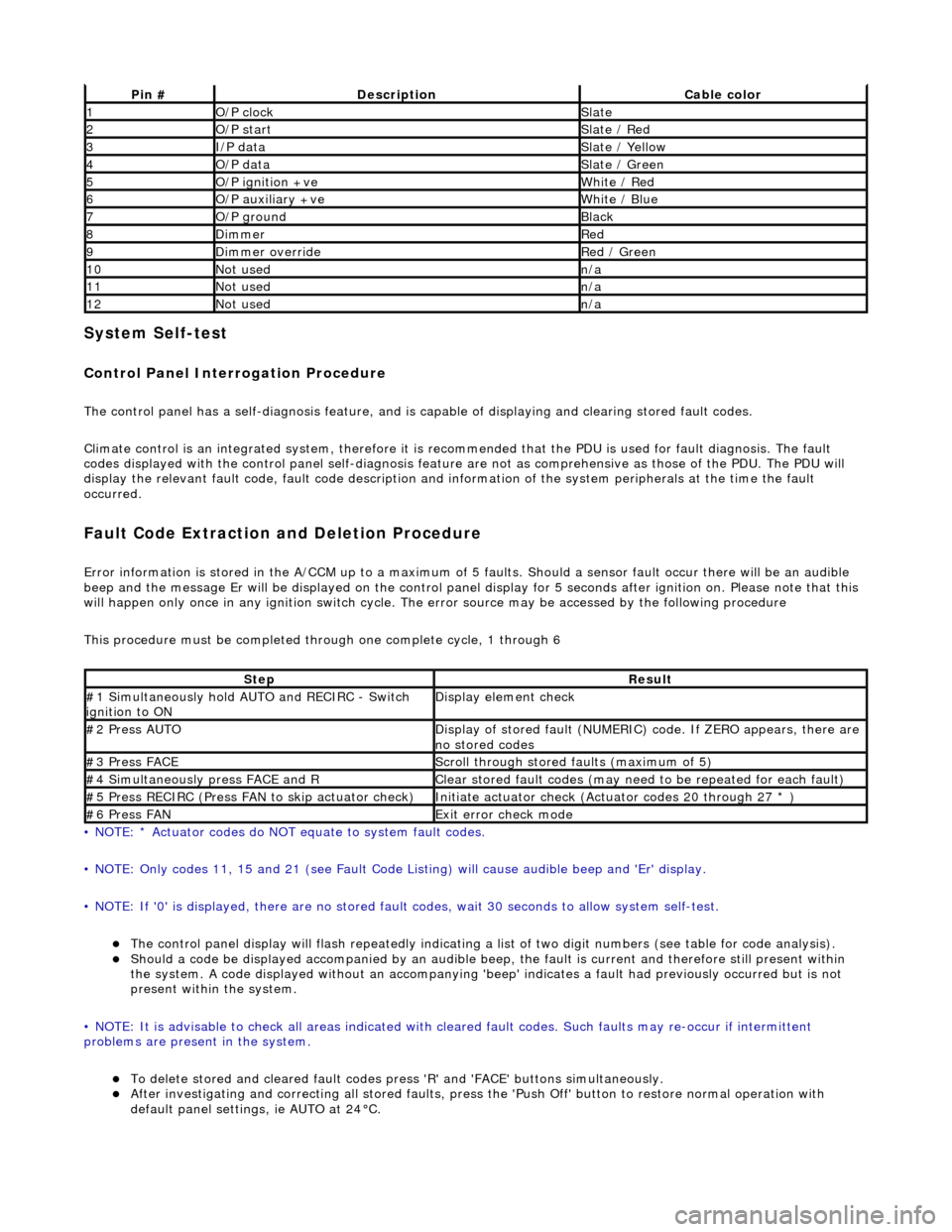
System Self-test
Control Panel Interrogation Procedure
The control panel has a self-diagnosis feature, and is capable of displaying and clearing stored fault codes.
Climate control is an integrated system, therefore it is recommended that the PDU is used for fault diagnosis. The fault
codes displayed with the control panel self -diagnosis feature are not as comprehensive as those of the PDU. The PDU will
display the relevant fault code, fault co de description and information of the system peripherals at the time the fault
occurred.
Fault Code Extraction and Deletion Procedure
Error information is stored in the A/CCM up to a maximum of 5 faults. Should a sensor fault occur there will be an audible
beep and the message Er will be displayed on the control panel display for 5 seco nds after ignition on. Please note that this
will happen only once in any ignition switch cycle. The error source may be accessed by the following procedure
This procedure must be completed through one complete cycle, 1 through 6
• NOTE: * Actuator codes do NOT equate to system fault codes.
• NOTE: Only codes 11, 15 and 21 (see Fault Code List ing) will cause audible beep and 'Er' display.
• NOTE: If '0' is displayed, there are no stored faul t codes, wait 30 seconds to allow system self-test.
The control panel display will flash repeatedly indicating a list of two digit numbers (see table for code analysis). Should a code be displayed accompanied by an audible beep, the fault is current and therefore still present within
the system. A code displayed without an accompanying 'bee p' indicates a fault had previously occurred but is not
present within the system.
• NOTE: It is advisable to check all areas indicated with cleared fault codes. Such faults may re-occur if intermittent
problems are present in the system.
To delete stored and cleared fault codes press 'R' and 'FAC E' buttons simultaneously. After investigating and correcting all stored faults, press the 'Push Off' button to restore normal operation with
default panel settings, ie AUTO at 24°C.
Pin #DescriptionCable color
1O/P clockSlate
2O/P startSlate / Red
3I/P dataSlate / Yellow
4O/P dataSlate / Green
5O/P ignition +veWhite / Red
6O/P auxiliary +veWhite / Blue
7O/P groundBlack
8DimmerRed
9Dimmer overrideRed / Green
10Not usedn/a
11Not usedn/a
12Not usedn/a
StepResult
#1 Simultaneously hold AU TO and RECIRC - Switch
ignition to ONDisplay element check
#2 Press AUTODisplay of stored fault (NUMERIC) code. If ZERO appears, there are
no stored codes
#3 Press FACEScroll through stored faults (maximum of 5)
#4 Simultaneously press FACE and RClear stored fault codes (may need to be repeated for each fault)
#5 Press RECIRC (Press FAN to skip actuator check)Initiate actuator check (Actuator codes 20 through 27 * )
#6 Press FANExit error check mode