panel JAGUAR X308 1998 2.G Manual Online
[x] Cancel search | Manufacturer: JAGUAR, Model Year: 1998, Model line: X308, Model: JAGUAR X308 1998 2.GPages: 2490, PDF Size: 69.81 MB
Page 1837 of 2490
System Self-test
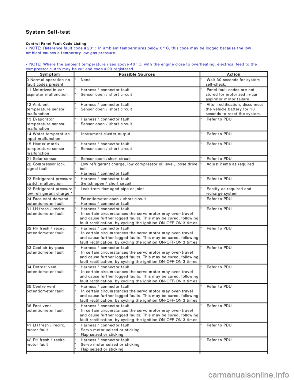
Control Panel Fault Code Listing • NOTE: Reference fault code #23*: In ambient temperatures below 0° C, this code may be logged because the low
ambient causes a tempor ary low gas pressure.
• NOTE: Where the ambient temperature rises above 40° C, with the engine close to overheating, electrical feed to the
compressor clutch may be cut and code #23 registered.
SymptomPossible SourcesAction
0 Normal operation no
fault codes presentNone
*Wait 30 seconds for system
self-check.
*
11 Motorized in-car
aspirator malfunctionHarness / connector fault
Sensor open / short circuit
*
*Panel fault codes are not
stored for motorized in-car
aspirator motor failure.
*
12 Ambient
temperature sensor
malfunctionHarness / connector fault
Sensor open / short circuit
*
*After rectification, disconnect
the vehicle battery for 10
seconds to reset the system.
*
13 Evaporator
temperature sensor
malfunctionHarness / connector fault
Sensor open / short circuit
*
*Refer to PDU
*
14 Water temperature
input malfunctionInstrument cl uster output
*Refer to PDU
*
15 Heater matrix
temperature sensor
malfunctionHarness / connector fault
Sensor open / short circuit
*
*Refer to PDU
*
21 Solar sensorSensor open /short circuit
*Refer to PDU
*
22 Compressor lock
signal faultLow refrigerant charge, low compressor oil level, loose drive
belt Harness / connector fault
*
*Adjust items as required
*
23 Refrigerant pressure
switch malfunctionHarness / connector fault
Switch open / short circuit
*
*Refer to PDU
*
23 Refrigerant pressure
low refrigerant charge * Leak from damaged pipe or joint
*Rectify as required and
recharge system
*
24 Face vent demand
potentiometer faultPotentiometer open / short circuit
Harness / connector fault
*
*Refer to PDU
*
31 LH fresh / recirc.
potentiometer faultHarness / connector fault
In certain circumstances the servo motor may over-travel
and cause further logged faults. This may be cured, following
fault rectification, by cycling the ignition ON-OFF-ON 3 times
*
*Refer to PDU
*
32 RH fresh / recirc.
potentiometer faultHarness / connector fault
In certain circumstances the servo motor may over-travel
and cause further logged faults. This may be cured, following
fault rectification, by cycling the ignition ON-OFF-ON 3 times
*
*Refer to PDU
*
33 Cool air by-pass
potentiometer faultHarness / connector fault
In certain circumstances the servo motor may over-travel
and cause further logged faults. This may be cured, following
fault rectification, by cycling the ignition ON-OFF-ON 3 times
*
*Refer to PDU
*
34 Defrost vent
potentiometer faultHarness / connector fault
In certain circumstances the servo motor may over-travel
and cause further logged faults. This may be cured, following
fault rectification, by cycling the ignition ON-OFF-ON 3 times
*
*Refer to PDU
*
35 Centre vent
potentiometer faultHarness / connector fault
In certain circumstances the servo motor may over-travel
and cause further logged faults. This may be cured, following
fault rectification, by cycling the ignition ON-OFF-ON 3 times
*
*Refer to PDU
*
36 Foot vent
potentiometer faultHarness / connector fault
In certain circumstances the servo motor may over-travel
and cause further logged faults. This may be cured, following
fault rectification, by cycling the ignition ON-OFF-ON 3 times
*
*Refer to PDU
*
41 LH fresh / recirc.
motor faultHarness / connector fault
Servo motor seized or sticking
Flap seized or sticking
*
*
*Refer to PDU
*
42 RH fresh / recirc.
motor faultHarness / connector fault
Servo motor seized or sticking
Flap seized or sticking
*
*
*Refer to PDU
*
Page 1838 of 2490
System Self-test
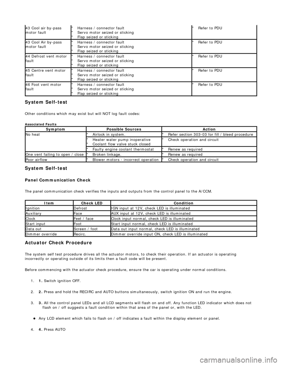
Other conditions which may exist but will NOT log fault codes:
Associated Faults
System Self-test
Panel Communication Check
The panel communication check veri fies the inputs and outputs from the control panel to the A/CCM.
Actuator Check Procedure
The system self test procedure drives all the actuator moto rs, to check their operation. If an actuator is operating
incorrectly or operating outside of its limi ts then a fault code will be present.
Before commencing with the actuator check procedure, ensure the ca r is operating under normal conditions.
1. 1. Switch ignition OFF.
2. 2. Press and hold the RECIRC and AUTO buttons simult aneously, switch ignition ON and run the engine.
3. 3. All the control panel LEDs and all LCD segments will flas h on and off. Any function LED indicator which does not
flash on / off suggests a fault condition within that area of the panel or, with the LED.
Any LCD element which fails to flash on / off indicates a fault within the display element or panel.
4. 4. Press AUTO
43 Cool air by-pass
motor faultHarness / connector fault
Servo motor seized or sticking
Flap seized or sticking
*
*
*Refer to PDU
*
43 Cool Air by-pass
motor faultHarness / connector fault
Servo motor seized or sticking
Flap seized or sticking
*
*
*Refer to PDU
*
44 Defrost vent motor
faultHarness / connector fault
Servo motor seized or sticking
Flap seized or sticking
*
*
*Refer to PDU
*
45 Centre vent motor
faultHarness / connector fault
Servo motor seized or sticking
Flap seized or sticking
*
*
*Refer to PDU
*
46 Foot vent motor
faultHarness / connector fault
Servo motor seized or sticking
Flap seized or sticking
*
*
*Refer to PDU
*
SymptomPossible SourcesAction
No heatAirlock in system.
*Refer section 303-03 for fill / bleed procedure
*
Heater water pump inoperative
Coolant flow valve stuck closed
*
*Check operation and circuit
*
Faulty engine coolant thermostat
*Renew as required
*
One vent failing to open / closeBroken linkage.
*Renew as required
*
Poor airflowBlower motors - incorrect operation
*Check operation and circuit
*
ItemCheck LEDCondition
IgnitionDefrostIGN input at 12V, check LED is illuminated
AuxiliaryFaceAUX input at 12V, check LED is illuminated
ClockFeet / faceClock input normal, check LED is illuminated
Start inputFootStart input normal, check LED is illuminated
Data outScreen / footData out input normal, check LED is illuminated
Dimmer overrideRecirc.Dimmer override input ON, check LED is illuminated
Page 1839 of 2490
5.5. Press RECIRC button to instigate actuator check mode.
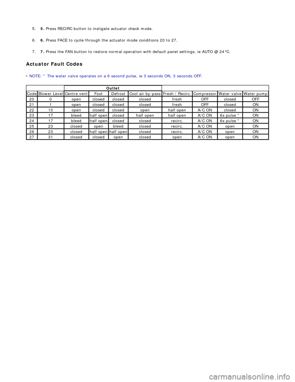
6. 6. Press FACE to cycle through the actu ator mode conditions 20 to 27.
7. 7. Press the FAN button to restore normal operation with default panel settings, ie AUTO @ 24°C.
Actuator Fault Codes
• NOTE: * The water valve operates on a 6 second pulse, ie 3 seconds ON, 3 seconds OFF.
Outlet
Code Blower Level Centre vent Foot Defrost Cool air by-pass Fresh / Recirc. Compressor Water valve Water pump
200openclosedclosedclosedfreshOFFclosedOFF
211openclosedclosedclosedfreshOFFclosedON
2210openclosedclosedopenhalf openA/C ONclosedON
2317bleedhalf openclosedhalf openhalf openA/C ON6s pulse * ON
2417bleedhalf openclosedclosedrecirc.A/C ON6s pulse * ON
2523closedopenbleedclosedrecirc.A/C ONopenON
2623closedhalf openhalf openclosedrecirc.A/C ONopenON
2731closedclosedopenclosedopenA/C ONopenON
Page 1842 of 2490
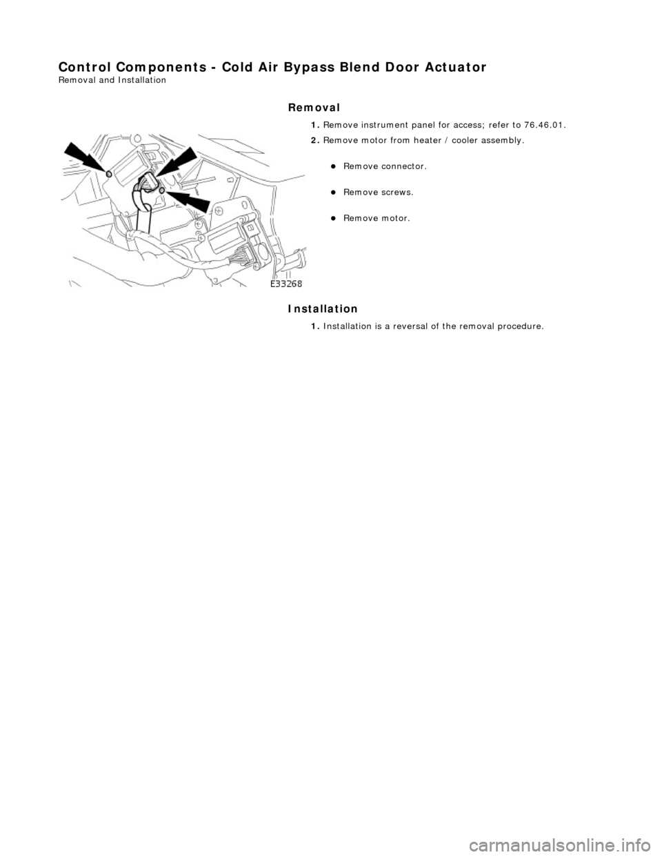
Control Components - Cold Air Bypass Blend Door Actuator
Removal and Installation
Removal
Installation
1.
Remove instrument panel for access; refer to 76.46.01.
2. Remove motor from heater / cooler assembly.
Remove connector.
Remove screws.
Remove motor.
1. Installation is a reversal of the removal procedure.
Page 1844 of 2490
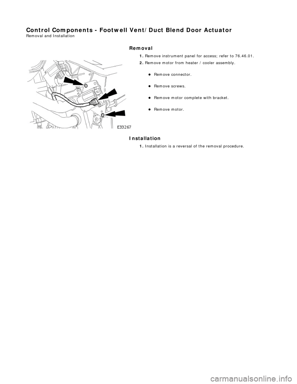
Control Components - Footwell Vent/Duct Blend Door Actuator
Removal and Installation
Removal
Installation
1.
Remove instrument panel for access; refer to 76.46.01.
2. Remove motor from heater / cooler assembly.
Remove connector.
Remove screws.
Remove motor complete with bracket.
Remove motor.
1. Installation is a reversal of the removal procedure.
Page 1845 of 2490
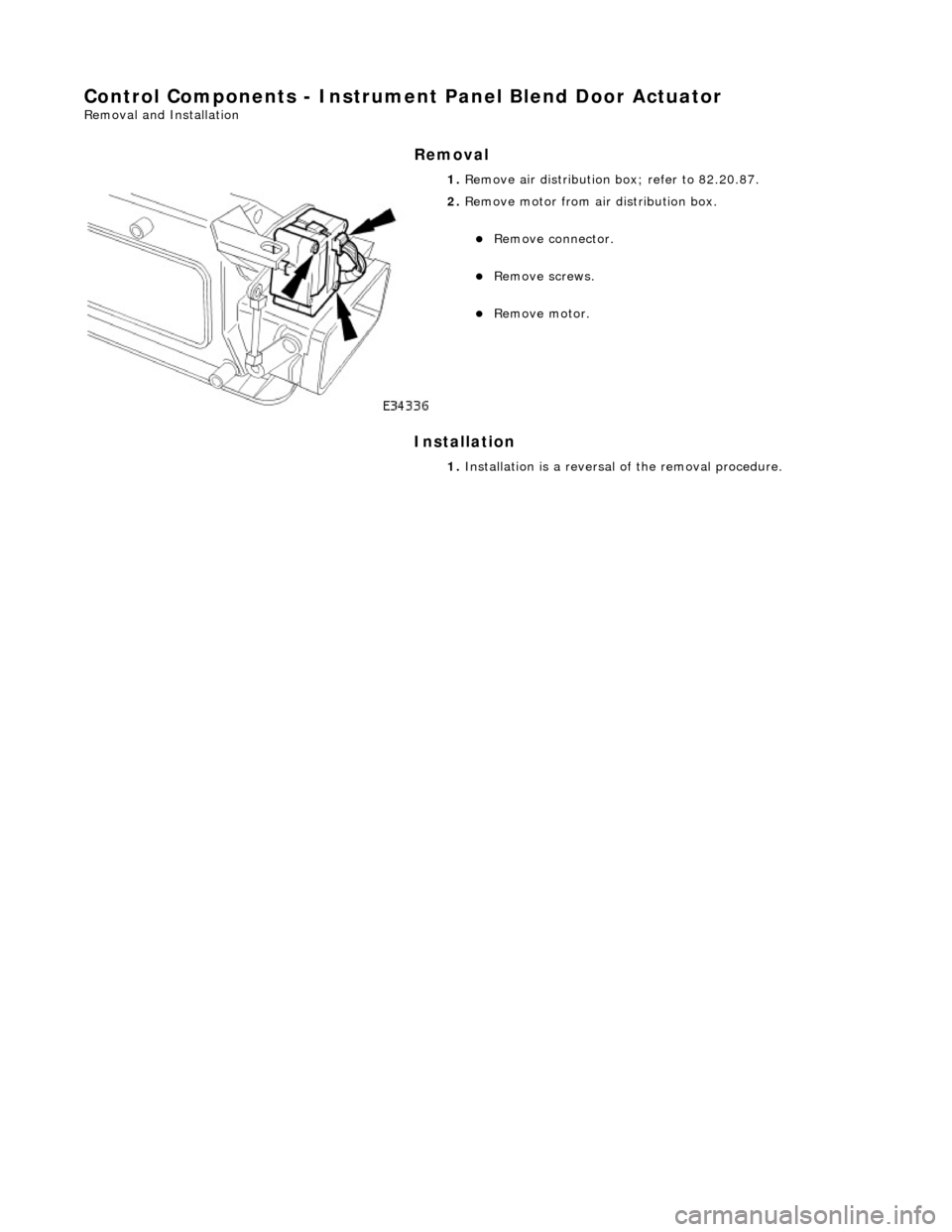
Control Components - Instrument Panel Blend Door Actuator
Removal and Installation
Removal
Installation
1.
Remove air distribution box; refer to 82.20.87.
2. Remove motor from air distribution box.
Remove connector.
Remove screws.
Remove motor.
1. Installation is a reversal of the removal procedure.
Page 1852 of 2490
Instrument Cluster and Panel Illumination - Instrument Cluster and Panel
Illumination
Description and Operation
Details on the Instrument Cluster and Panel Illumination can be found in sections 413-01, 413-06, 413-07 and 413-08.
Page 1853 of 2490
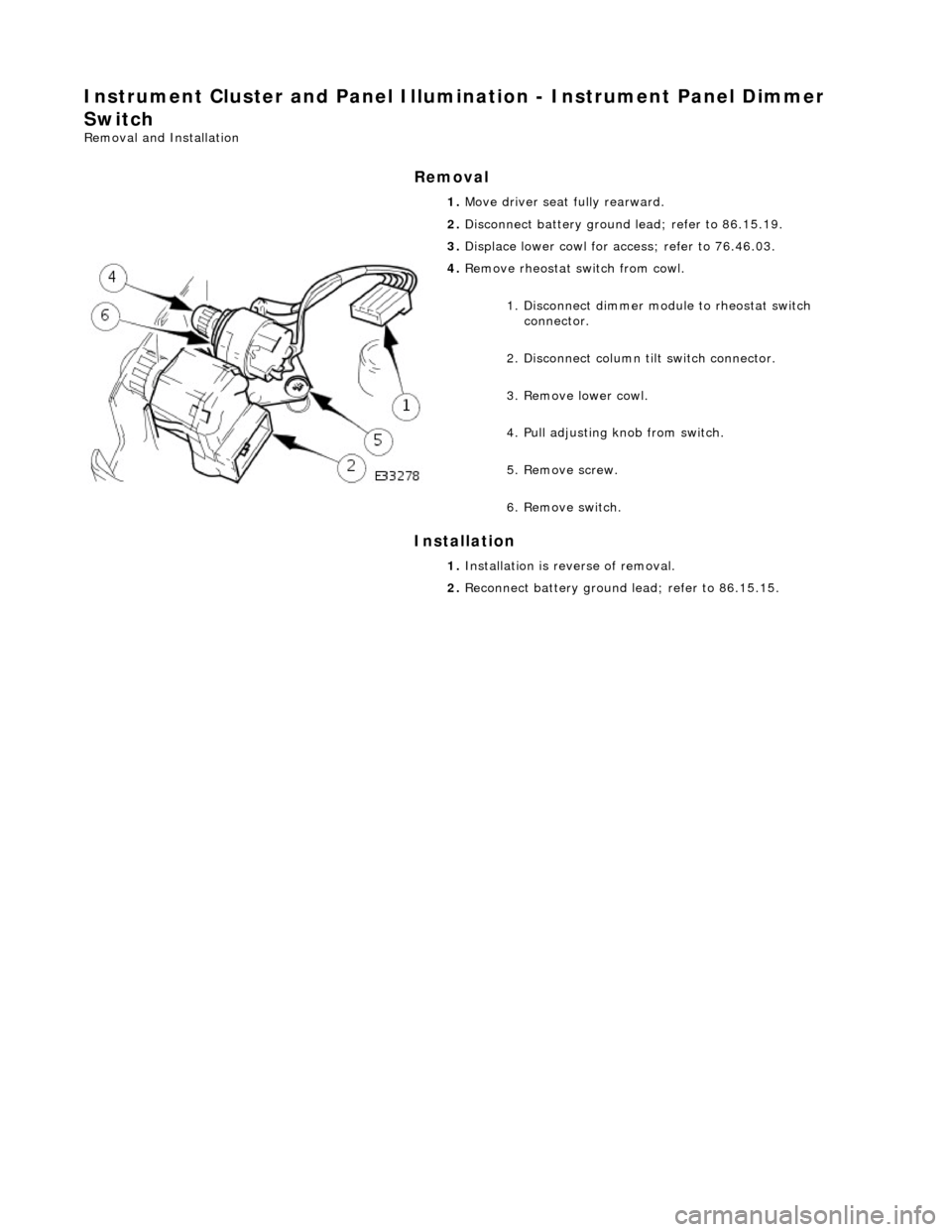
Instrument Cluster and Panel Illumination - Instrument Panel Dimmer
Switch
Removal and Installation
Removal
Installation
1.
Move driver seat fully rearward.
2. Disconnect battery ground lead; refer to 86.15.19.
3. Displace lower cowl for access; refer to 76.46.03.
4. Remove rheostat sw itch from cowl.
1. Disconnect dimmer module to rheostat switch connector.
2. Disconnect column tilt switch connector.
3. Remove lower cowl.
4. Pull adjusting knob from switch.
5. Remove screw.
6. Remove switch.
1. Installation is reverse of removal.
2. Reconnect battery ground lead; refer to 86.15.15.
Page 1857 of 2490
Instrume
nt Cluster - Instrument Cluster
Re
moval and Installation
Remov
al
1.
Adjust steer
ing column to full
y extended and lowered position.
2. Remove battery cover and disc onnect ground cable from
battery terminal. Refer to 86.15.19.
3. Remove veneer from instrument panel. Refer to 76.47.24.
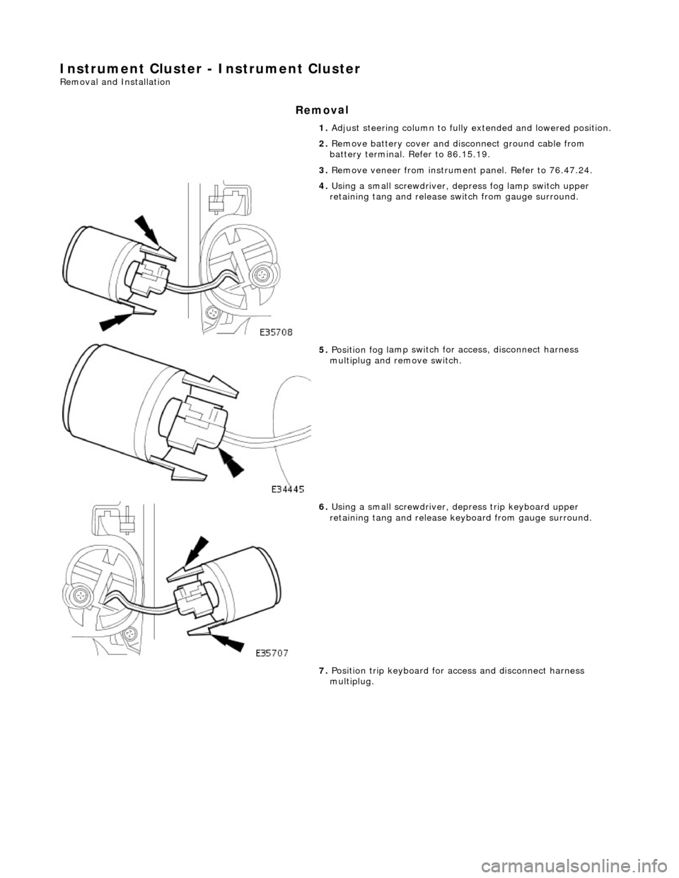
4. Using a small
screwdriver, de
press fog lamp switch upper
retaining tang and release sw itch from gauge surround.
5. Position fog l
amp switch fo
r access, disconnect harness
multiplug and remove switch.
6. Using a small
screwdriver, depress trip keyboard upper
retaining tang and release ke yboard from gauge surround.
7. Position trip keyboard for ac cess and disconnect harness
multiplug.
Page 1858 of 2490
In
stallation
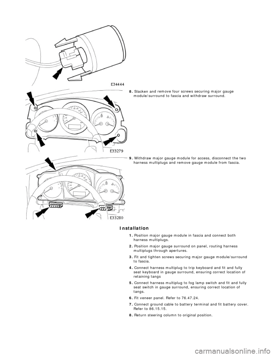
8.
Slac ken an
d remove four screws securing major gauge
module/surround to fascia and withdraw surround.
9. With draw major gau
ge module fo
r access, disconnect the two
harness multiplugs and remove gauge module from fascia.
1. Position major gauge module in fascia and connect both
harness multiplugs.
2. Position major gauge surround on panel, routing harness
multiplugs through apertures.
3. Fit and tighten screws securing major gauge module/surround
to fascia.
4. Connect harness multiplug to tr ip keyboard and fit and fully
seat keyboard in gauge surround, ensuring correct location of
retaining tangs
5. Connect harness multiplug to fog lamp switch and fit and fully
seat switch in gaug e surround, ensuring correct location of
tangs.
6. Fit veneer panel. Refer to 76.47.24.
7. Connect ground cable to battery terminal and fit battery cover.
Refer to 86.15.15.
8. Return steering column to original position.