JAGUAR X308 1998 2.G Workshop Manual
Manufacturer: JAGUAR, Model Year: 1998, Model line: X308, Model: JAGUAR X308 1998 2.GPages: 2490, PDF Size: 69.81 MB
Page 1141 of 2490
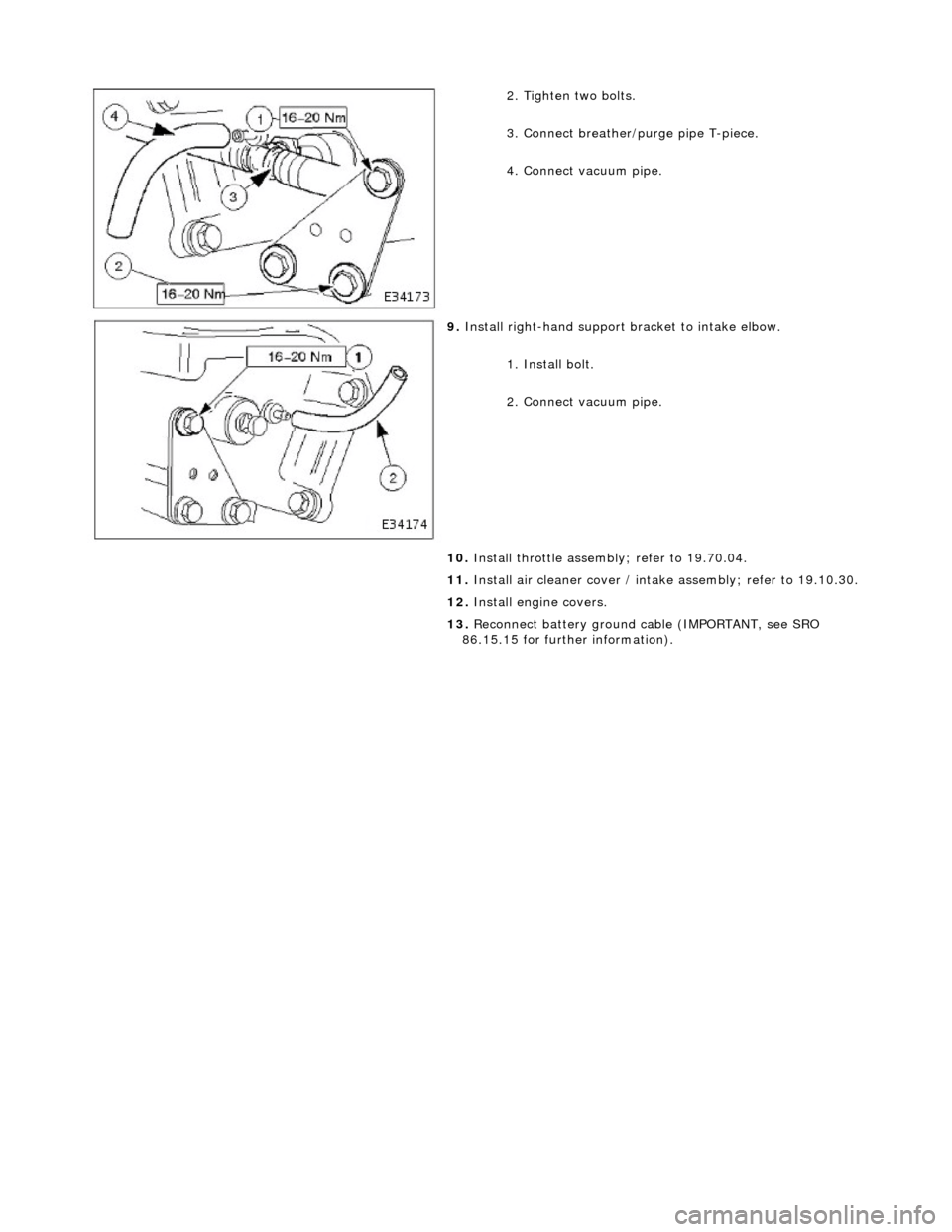
2.
Tighten two bolts.
3. Connect breather/p urge pipe T-piece.
4. Connect vacuum pipe.
9. Install righ
t-hand support
bracket to intake elbow.
1. Install bolt.
2. Connect vacuum pipe.
10. Install throttle assemb ly; refer to 19.70.04.
11. Install air cleaner cover / intake assembly; re fer to 19.10.30.
12. Install engine covers.
13. Reconnect battery ground cable (IMPORTANT, see SRO
86.15.15 for further information).
Page 1142 of 2490
Intake Air Distribution and Filtering - Throttle B
ody Elbow4.0L SC V8 -
AJ26
Re mo
val and Installation
Remova
l
1.
WARNING: BE
FORE PROCEEDING, IT IS ESSENTIAL THAT
WARNING NOTES GIVEN IN SECTION 100-00 (UNDER HEADING
'SAFETY PRECAUTIONS') AR E READ AND UNDERSTOOD.
Disconnect battery ground cable (IMPORTANT, see SRO
86.15.19 for further information).
2. Re
move air cleaner cover / inta
ke assembly; refer 19.10.30.
3. Remove throttle assemb ly; refer to 19.70.04.
4. Remove exhaust gas recirculation (EGR) valve where installed;
refer 17.45.01.
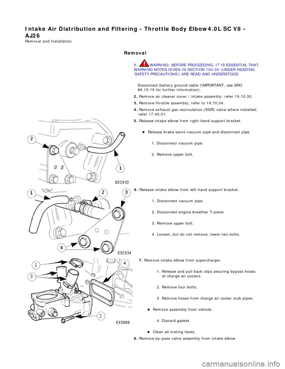
5. Re
lease intake elbow from right-hand support bracket.
Re
lea
se brake servo vacuum pi
pe and disconnect pipe.
1. Disconnect vacuum pipe.
2. Remove upper bolt.
6. Relea
se intake elbow from le
ft-hand support bracket.
1. Disconnect vacuum pipe.
2. Disconnect engine breather T-piece.
3. Remove upper bolt.
4. Loosen, but do not remove, lower two bolts.
7. Re
move intake elbow from supercharger.
1. Release and pull back cl ips securing bypass hoses
at charge air coolers.
2. Remove four bolts.
3. Remove hoses from charge air cooler stub pipes.
Re move as
sembly from vehicle.
4. Discard gasket.
Cle a
n all mating faces.
8. Remove by-pass valve assembly from intake elbow.
Page 1143 of 2490
I
nstallation
1.
Remove two bolts.
Re
move by-pass assembly from
elbow and discard O-ring.
9. Where necessary, remove blanki ng plate from intake elbow.
Re
move bolts.
Di
scard gasket.
Cle
an all mating faces.
1. Where necessary, install blanking plate to intake elbow.
Inst
all new gasket.
Inst
all bolts (18-24Nm).
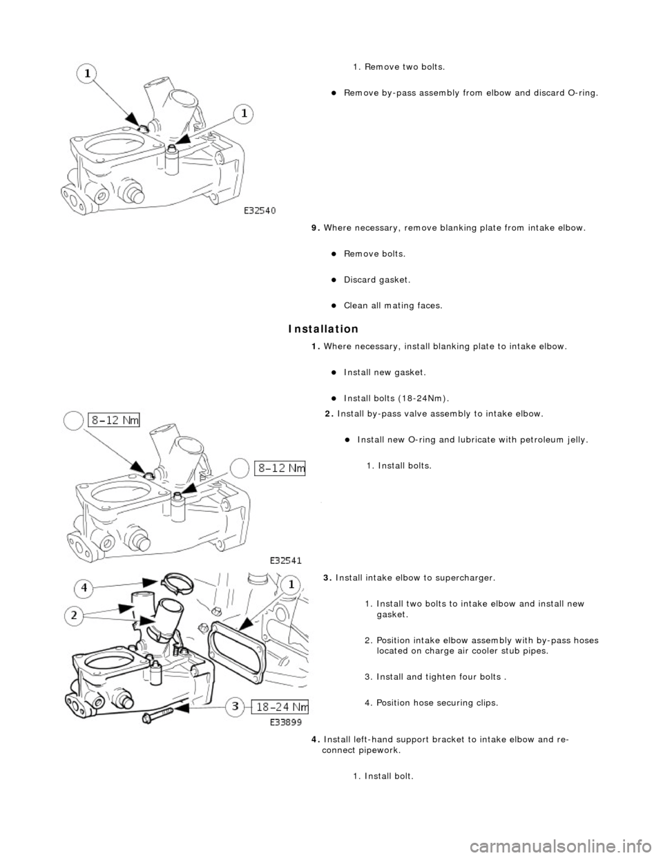
2. Inst
all by-pass valve assembly to intake elbow.
Inst
all new O-ring and lubricate with petroleum jelly.
1. Install bolts.
3. Install
intake elbow to supercharger.
1. Install two bolts to intake elbow and install new gasket.
2. Position intake elbow assembly with by-pass hoses located on charge air cooler stub pipes.
3. Install and tighten four bolts .
4. Position hose securing clips.
4. Install left-hand support brac ket to intake elbow and re-
connect pipework.
1. Install bolt.
Page 1144 of 2490
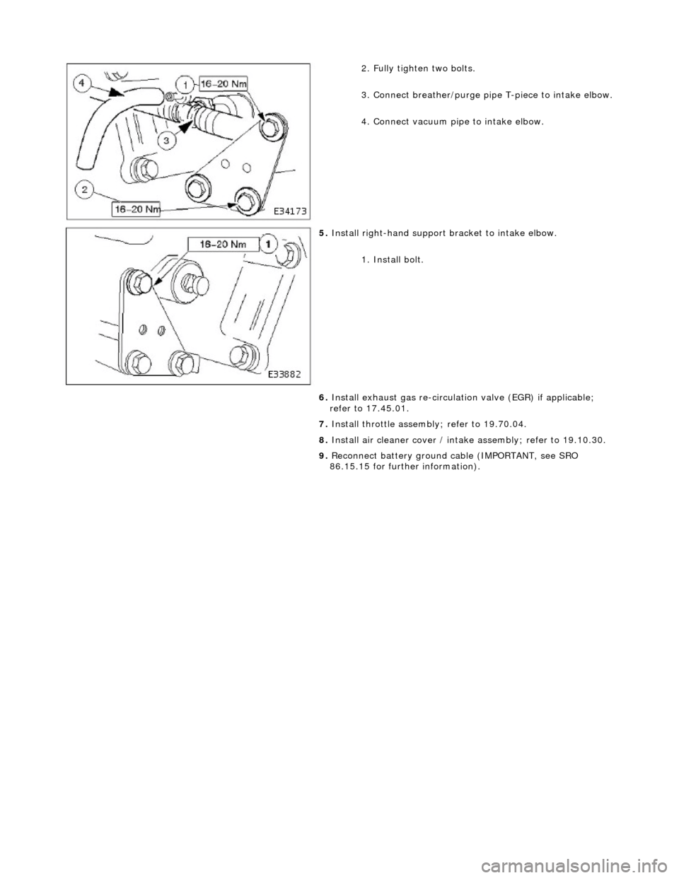
2.
Fully tighten two bolts.
3. Connect breather/purge pipe T-piece to intake elbow.
4. Connect vacuum pipe to intake elbow.
5. Install right-hand support brac
ket to intake elbow.
1. Install bolt.
6. Install exhaust gas re-circulation valve (EGR) if applicable;
refer to 17.45.01.
7. Install throttle assemb ly; refer to 19.70.04.
8. Install air cleaner cover / intake assembly; refer to 19.10.30.
9. Reconnect battery ground cable (IMPORTANT, see SRO
86.15.15 for further information).
Page 1145 of 2490

Intake Air Distribution and Filtering - Throt
tle Body Elbow Gasket
Re
moval and Installation
Remov
al
Installation
1.
R
emove throttle intake elbo
w; refer to (SC)19.70.28.
1. Installation is a reversal of the removal procedure.
Page 1146 of 2490
Intake Air Distribution and Filtering - Throttle B
ody Elbow Gasket4.0L NA
V8 - AJ27/3.2L NA V8 - AJ26
Re mo
val and Installation
Remova
l
Installation
1.
Re
move throttle intake el
bow; refer to 19.70.28.
1. Installation is a reversal of the removal procedure.
Page 1147 of 2490
Intake Air Distribution and Filtering - Throt
tle Body Elbow Gasket4.0L SC
V8 - AJ26
Re
moval and Installation
Remov
al
Installation
1.
R
emove throttle intake elbo
w; refer to (SC)19.70.28.
1. Installation is a reversal of the removal procedure.
Page 1148 of 2490
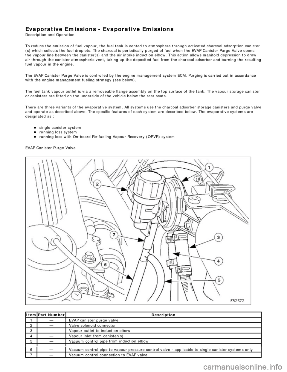
Evaporative E
missions - Evaporative Emissions
Description an
d Operation
To reduce the emission of fuel vapour, th e fuel tank is vented to atmosphere through activated charcoal adsorption canister
(s) which collects the fuel droplets. The ch arcoal is periodically purged of fuel when the EVAP Canister Purge Valve opens
the vapour line between the canister(s) and the air intake induct ion elbow. This action allows manifold depression to draw
air through the canister atmospheric vent, taking up the deposited fuel from the charcoal adsorber and burning the resulting
fuel vapour in the engine.
The EVAP Canister Purge Valve is controlled by the engine management system ECM. Purging is carried out in accordance
with the engine management fu eling strategy (see below).
The fuel tank vapour outlet is via a removeable flange assemb ly on the top surface of the tank. The vapour storage canister
or canisters are fitted on the underside of the vehicle below the rear seats.
There are three variants of the evaporativ e system. All systems use the charcoal adsorber storage canisters and purge valve
and operate as described above. The specific features of each system are described below. The evaporative systems are
designated as :
sin g
le canister system
ru
nn
ing loss system
ru
nn
ing loss with On-board Re-fueling Vapour Recovery (ORVR) system
EVAP Canister Purge Valve
Ite
m
Par
t
Number
De
scr
iption
1—EVAP canister purge v
alve
2—Valve s
olenoid connector
3—Vapour outlet to indu
ction elbow
4—Vapour
inlet from canister(s)
5—Vacuum contro
l pi
pe from induction elbow
6—Vacuum contro
l pi
pe to vapour pressure control va
lve - applicable to single canister systems only
7—Vacuum
control connection to EVAP valve
Page 1149 of 2490
The E
VAP canister purge valve controls th
e flow rate of fuel vapour drawn into the engine during the canister purge
operation. The valve is opened by a vacu um feed from the induction elbow : the vacu um feed is controlled by the integral
valve solenoid and is applied when the so lenoid is energised. The solenoid is pulsed on (energised) and off by a fixed
frequency (100Hz) variable pulse width control signal (pulse width modulation). By varying the pulse on to off time, the
ECM controls the duty cycle of the valve (time that the valve is open to time closed) and thus the vapour flow rate to the
engine.
With no ECM signal applied to the va lve solenoid, the valve remains closed.
Can
ister Purge Operation
The
following pre-conditions are ne
cessary for purging to commence :
aft
er battery disconnection/reconnection, engine
management adaptations must be re-instated.
engine has run for
at least 8 seconds.
engi
ne coolant temperature is not less than 70 °C.
engine
not running in the fuel
cut off condition (eg overrun).
t
he adaptive fuel correction
function has not registered a rich or lean failure
t
he evaporative emission leak test has not failed
no faults have been diagnosted in th
e rel
evant sensor and valve circuits -
Air Flow Meter (AFM), Engine Coolant
Temperature sensor, Evaporativ e Canister Purge valve and Canister Close Valve (CCV).
If these conditions have been satisfied, purging is started. If any failures are registered, purging is inhibited.
The canister(s) is purged during each driv e cycle at various rates in accordance with the prevailing engine conditions. The
engine management software st ores a map of engine speed (RPM) against engine load (grams of air inducted / rev). For
any given engine speed and load, a vapour purge rate is assigned (purge rate increases with engine speed and load).
The preset purge rates are base d on the assumption of a vapour concentratio n of 100%. The actual amount of vapour is
measured by the closed loop fueling system : the input of evaporative fuel into the engine causes the outputs from the
upstream oxygen sensors to change, the am ount of change providing a measure of the vapour concentration. This feedback
causes the original purge rate to be adju sted and also reduces the amount of fuel input via the injectors to maintain the
correct air to fuel ratio.
Engine speed/load mapping and the corresp onding purge rates are different for single canister, running loss and ORVR
evaporative systems.
Page 1150 of 2490
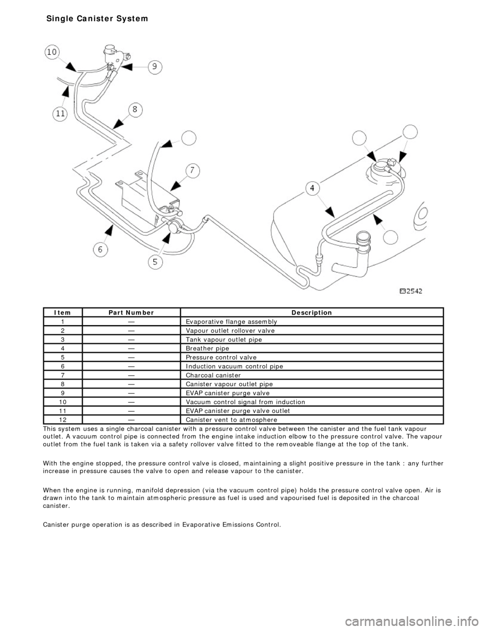
Thi s
system uses a single charcoal canister with a pressure
control valve between the canister and the fuel tank vapour
outlet. A vacuum control pipe is connecte d from the engine intake induction elbow to the pressure control valve. The vapour
outlet from the fuel tank is taken via a safety rollover valve fitted to the re moveable flange at the top of the tank.
With the engine stopped, the pressure control valve is closed, maintaining a slight positive pre ssure in the tank : any further
increase in pressure causes the valve to open and release vapour to the canister.
When the engine is running, manifold depr ession (via the vacuum control pipe) holds the pressure control valve open. Air is
drawn into the tank to maintain atmospheric pressure as fuel is used and vapourised fuel is deposited in the charcoal
canister.
Canister purge operation is as described in Evaporative Emissions Control.
It e
m
Par
t
Number
De
scr
iption
1—Evaporative flan
ge assembly
2—Vapour outlet rol
lover valve
3—Tank vapour outlet pipe
4—Breather
pipe
5—Pressure control valve
6—Induct
ion vacuum control pipe
7—Charcoal can
i
ster
8—Canister vapour outlet pipe
9—EVAP canister purge v
a
lve
10—Vacuu
m
control sign
al from induction
11—EVAP ca
nister purge valve outlet
12—Canist
er vent
to atmosphere
Single Ca
nister System