JAGUAR X308 1998 2.G Workshop Manual
X308 1998 2.G
JAGUAR
JAGUAR
https://www.carmanualsonline.info/img/21/7640/w960_7640-0.png
JAGUAR X308 1998 2.G Workshop Manual
Trending: oxygen, SOLENOID, accessory drive, spark plugs, body mounting, AUX, Ground
Page 1371 of 2490
Automatic Transmission/Transaxle - 4.0L NA V8 - AJ27/3.2L NA V8 - AJ26
- Transmission Support Insulator
In-vehicle Repair
Removal
Installation
1. Raise the vehicle on a ramp to a suitable height for working on
the rear mounting.
2. Remove the bolt which secure s the engine rear mounting
rubber to the transmission.
3. Position a transmission jack under the transmission casing.
Take the weight of the transmission on the jack.
4. Remove the rear mounting rubber.
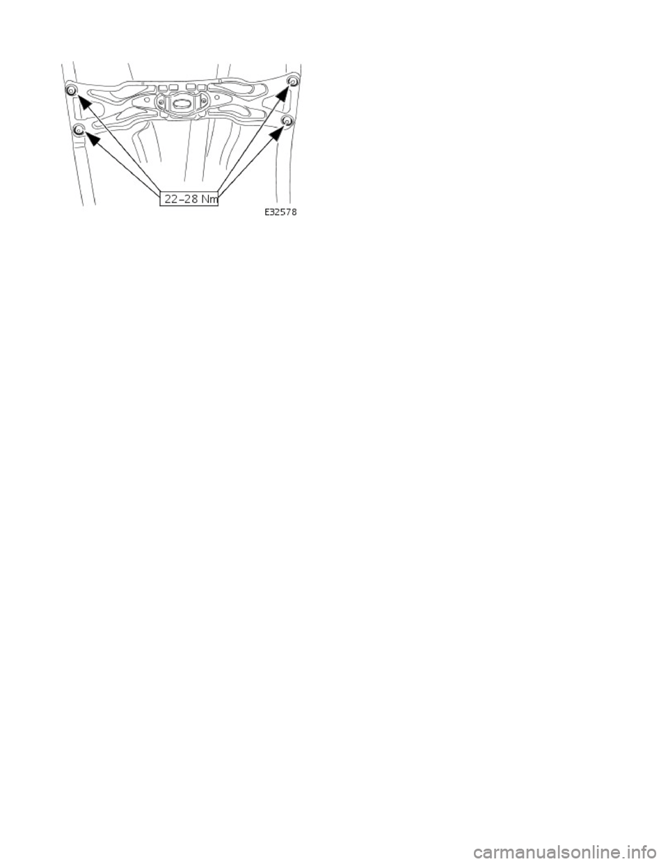
1. Slacken the four bolt s which secure the rear
crossmember to the vehicle floor.
2. Remove the two bolts which secure the mounting rubber to the crossmember.
3. Remove the mounting rubber.
1. Fit the mounting rubber assembly to position and tighten the
centre bolt to 30-40 Nm .
2. Tighten the crossmember to body bolts and the mounting
rubber to crossmember bolts to 22-28 Nm.
Page 1372 of 2490
Page 1373 of 2490
Automatic Transmission/Transaxle - 4.0L NA V8 - AJ27/3.2L NA V8 - AJ26
- Turbine Shaft Speed (TSS) Sensor
In-vehicle Repair
Removal
1. Disconnect battery ground cable.
Remove the battery cover.
2. Raise the vehicle on a lift.
2. WARNING: TRANSMISSION FLUID MAY CAUSE
SEVERE BURNS, ENSURE THAT ALL SAFETY PROCEDURES
ARE OBSERVED.
Carefully remove the drain plug and drain the
transmission fluid.
3. Remove the twenty-two bolts which secure the fluid pan.
Remove the fluid pan and all tr aces of gasket material.
4. Remove the input speed sensor.
• NOTE: M5 fixing.
1. Release the screw which secures the input speed sensor bracket and pull the sensor clear.
5. Disconnect the multiplug from the speed sensor.
Page 1374 of 2490
Installation
1.
NOTE: M5 fixing.
Connect the multiplug, install the input speed sensor and
securing bracket. Tighten the screw to the specified torque
figure.
2. NOTE: Ensure extreme clea nliness and never reuse
transmission fluid.
Using a new gasket, install the fl uid pan and tighten the twenty-
two fixings to the specified. torque figure.
3. Connect the battery and fit the battery cover..
Reset the radio and the clock.
4. Refer to (44.24.02) for fluid fill procedure.
Page 1375 of 2490
Automatic Transmission/Transaxle - 4.0L NA V8 - AJ27/3.2L NA V8 - AJ26
- Transmission
Removal
Removal
Special Tool(s)
Engine support
303-021
Engine lifting brackets
303-536
1. Select N gear position.
2. Open the engine compartment and fit paintwork protection
sheets.
3. Disconnect battery ground cable.
Remove the battery cover.
4. Remove the engine covers (12.30.06).
5. Remove the air intake tube, MAFM and air cleaner cover assy,
(19.10.30).
6. Install engine lifting bracket 303 - 536 at the rear RH.
7. Reposition the coolant he ader tank for access.
1. Remove the securing bolt.
Page 1376 of 2490
2. Reposition the tank.
8. Install engine lifting bracket 303 - 536 at the rear LH.
9. Support the engine using 303 - 021.
1. Adjust and locate the stan ds in the LH and RH fender
channels and tighten the beam fixings.
2. Engage the support hook s in the lifting brackets.
3. Tighten the support hook adjusters and take the weight of the engine.
10. Raise the vehicle for access.
11. Remove the LH downpipe cata lytic converter (17.50.09).
12. Remove the front muffler (30.10.18).
13. Remove the RH downpipe catalytic converter (17.50.09 and
17.50.10).
14. Drain the transmission fluid, (44.24.02).
15. Locate a transmission jack, Epco V-100 or similar, under the
transmission unit.
Adjust the angle of the jack to suit the transmission.
Secure the side clamps.
Pass the safety chain over the transmission unit and
secure.
Page 1377 of 2490
16. Remove the engine rear mounting bracket.
1. Remove the engine rear mounting to bracket bolt.
2. Remove the mounting bracket to body bolts.
17. Detach the driveshaft from th e transmission drive flange.
If the transmission is to be refitted, mark the position of
the coupling to drive flange.
17. CAUTION: Under no circ umstances remove the
driveshaft to flexible coupling fixings.
Remove the transmission drive flange to flexible coupling
three fixings.
18. Lower the transmission unit by carefully releasing the engine
support beam and by loweri ng the transmission jack.
19. Detach the gear selector cable from the transmission unit.
1. Remove the selector cable ball pin to selector lever nut.
2. Remove the selector cable to transmission casing bolts.
20. Disconnect the transmission harness multiplug.
1. Rotate the locking lever to release.
2. Disconnect the multiplug.
Page 1378 of 2490
21. Detach the rotary switch.
1. Remove the switch fixings.
2. Displace the switch harness from the clips.
22. Disconnect the fluid cooler pipes.
Unscrew the cooler pipe tube nu ts, one at each side of the
transmission casing.
Discard the 'O' rings.
Plug the pipes an d transmission.
23. Remove the three bolts which se cure the torque converter to
the drive plate.
1. Remove the access cover.
2. Rotate the crankshaft and hold to prevent movement, and remove the bolts.
24. Remove the LH and RH cataly st mounting brackets from the
transmission case.
Remove the bolts.
Page 1379 of 2490
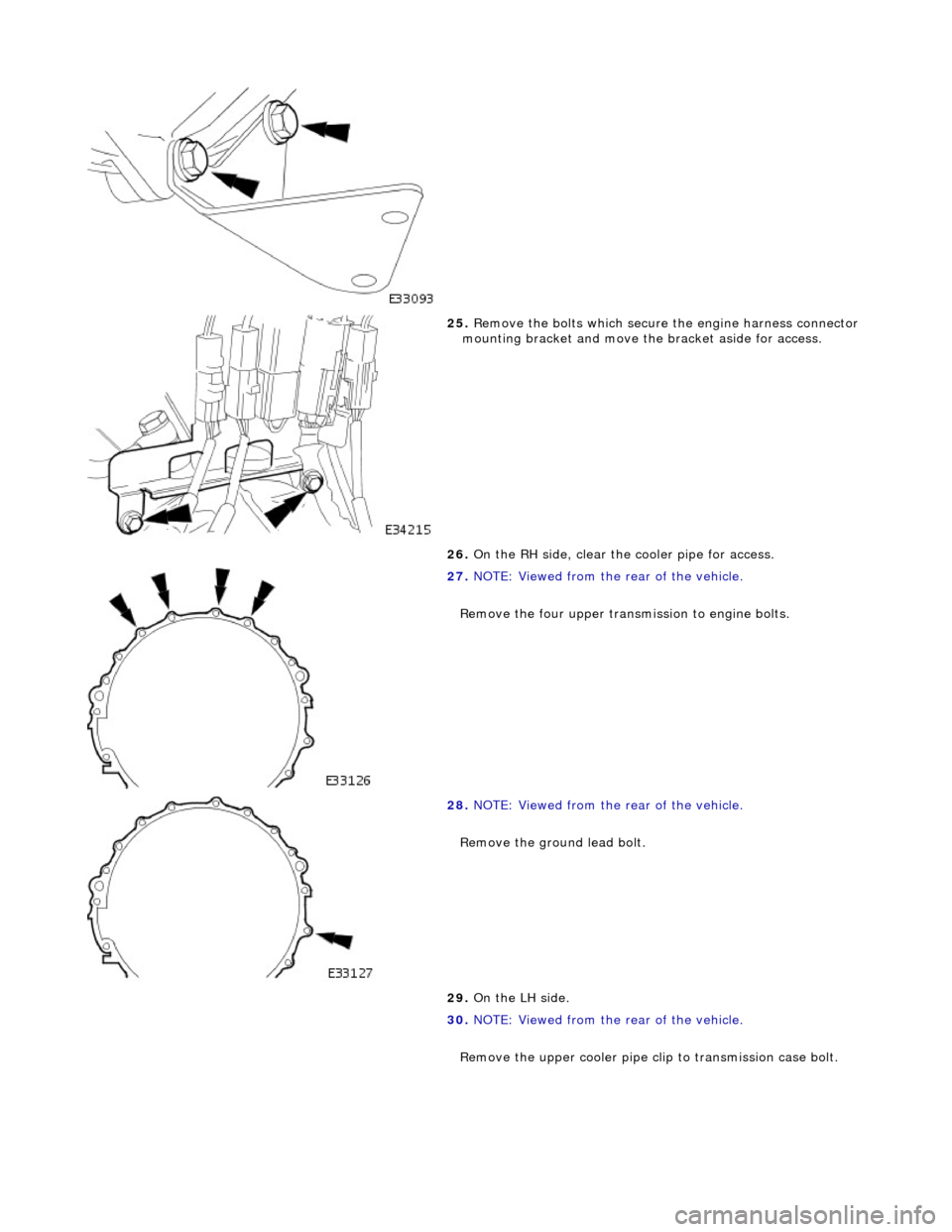
25. Remove the bolts which secure the engine harness connector
mounting bracket and move th e bracket aside for access.
26. On the RH side, clear the cooler pipe for access.
27. NOTE: Viewed from the rear of the vehicle.
Remove the four upper transmission to engine bolts.
28. NOTE: Viewed from the rear of the vehicle.
Remove the ground lead bolt.
29. On the LH side.
30. NOTE: Viewed from the rear of the vehicle.
Remove the upper cooler pipe c lip to transmission case bolt.
Page 1380 of 2490
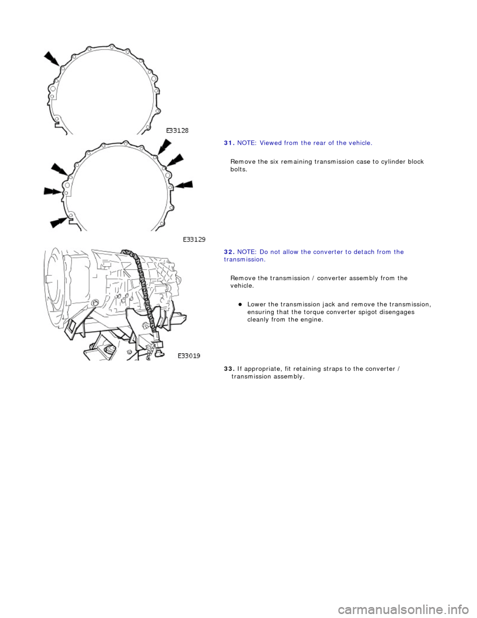
31.
NOTE: Viewed from the rear of the vehicle.
Remove the six remaining transmission case to cylinder block
bolts.
32. NOTE: Do not allow the converter to detach from the
transmission.
Remove the transmission / converter assembly from the
vehicle.
Lower the transmission jack and remove the transmission,
ensuring that the torque co nverter spigot disengages
cleanly from the engine.
33. If appropriate, fit retainin g straps to the converter /
transmission assembly.
Trending: valve, coolant reservoir, steering wheel adjustment, maintenance, rear bumper components, AUX, air bleeding


