JAGUAR X308 1998 2.G Workshop Manual
X308 1998 2.G
JAGUAR
JAGUAR
https://www.carmanualsonline.info/img/21/7640/w960_7640-0.png
JAGUAR X308 1998 2.G Workshop Manual
Trending: Fuel tank, oil filter, Steering column bolts, P1260, remove oxygen sensor, refilling coolant, language
Page 1341 of 2490
3. NOTE: Ensure extreme clea nliness and never reuse
transmission fluid.
Using a new gasket, install the fl uid pan and tighten the fixings
to the specified torque figure.
4. Connect the battery and fit the battery cover..
Reset the radio and the clock.
5. Refer to (44.24.02) for fluid fill procedure.
Page 1342 of 2490
Automatic Transmission/Transaxle - 4.0L NA V8 - AJ27/3.2L NA V8 - AJ26
- Extension Housing Seal
In-vehicle Repair
Removal
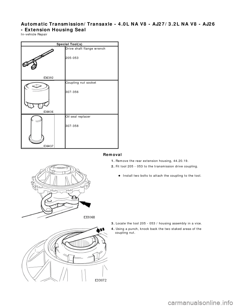
Special Tool(s)
Drive shaft flange wrench
205-053
Coupling nut socket
307-356
Oil seal replacer
307-358
1. Remove the rear extension housing, 44.20.19.
2. Fit tool 205 - 053 to the transmission drive coupling.
Install two bolts to attach the coupling to the tool.
3. Locate the tool 205 - 053 / housing assembly in a vice.
4. Using a punch, knock back the two staked areas of the
coupling nut.
Page 1343 of 2490
Installation
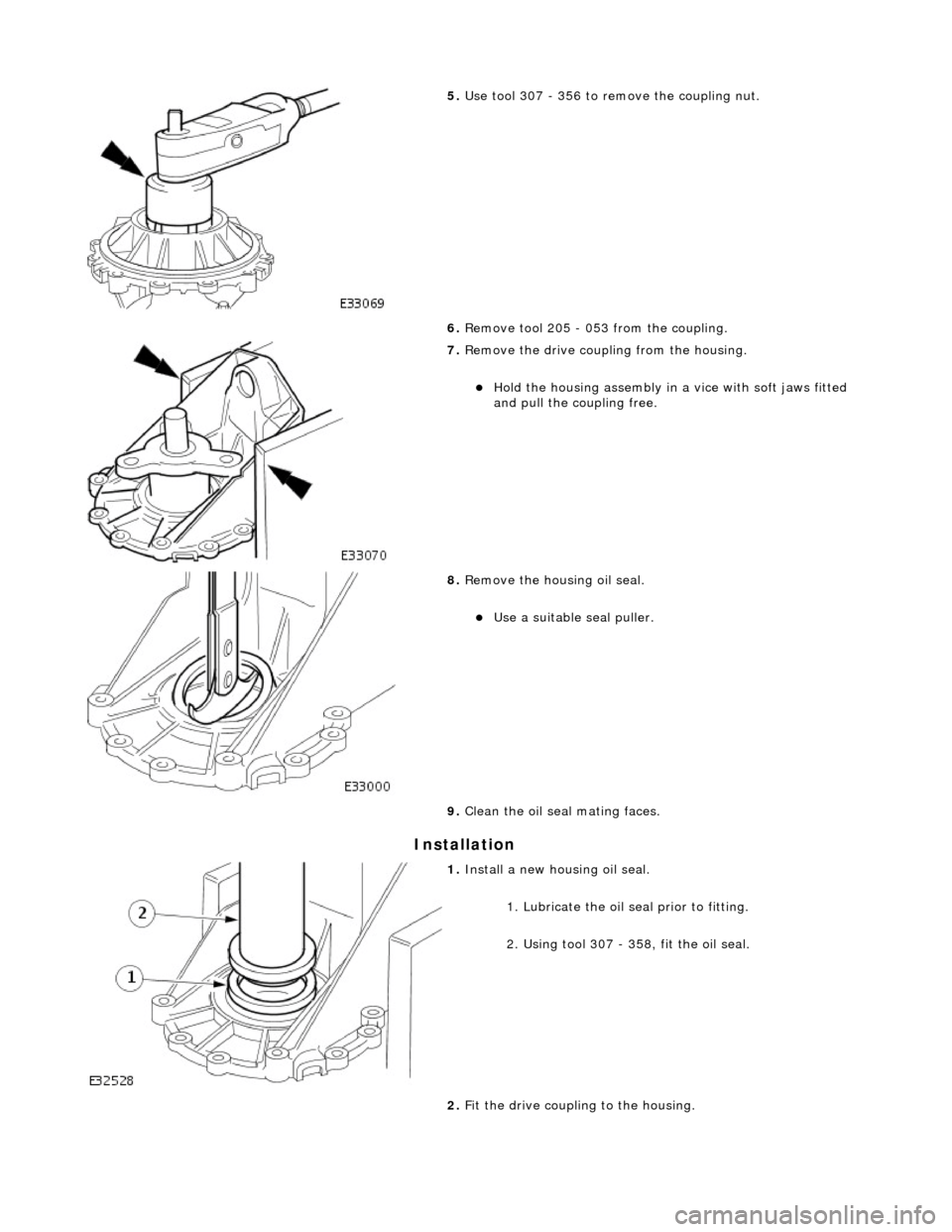
5. Use tool 307 - 356 to remove the coupling nut.
6. Remove tool 205 - 053 from the coupling.
7. Remove the drive coupling from the housing.
Hold the housing assembly in a vice with soft jaws fitted
and pull the co upling free.
8. Remove the housing oil seal.
Use a suitable seal puller.
9. Clean the oil seal mating faces.
1. Install a new housing oil seal.
1. Lubricate the oil se al prior to fitting.
2. Using tool 307 - 358, fit the oil seal.
2. Fit the drive coupling to the housing.
Page 1344 of 2490
Hold the housing assembly in a vice with soft jaws fitted
and carefully insert the coupling.
Fit tool 205 - 053 to the coupling.
3. Use tool 307 - 356 to tighten th e coupling nut to the specified
torque figure.
4. Stake the coupling nut at two positions.
5. Refit the rear extension housing. Refer to Operation 44.20.19.
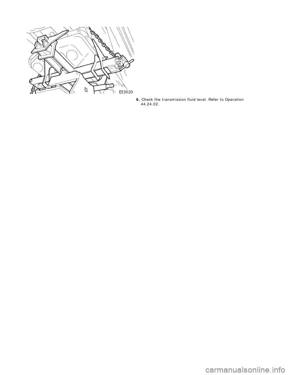
6. Check the transmission fluid level. Refer to Operation
44.24.02.
Page 1345 of 2490

Automatic Transmission/Transaxle - 4.0L NA V8 - AJ27/3.2L NA V8 - AJ26
- Extension Housing O-Ring Seal
In-vehicle Repair
Removal
1. Select N position.
2. Raise the vehicle for access.
3. Remove the front muffler, 30.10.18.
4. Locate a transmission jack, Epco V-100 or similar, under the
transmission unit.
Adjust the angle of the jack to suit the transmission.
Secure the side clamps.
Pass the safety chain over the transmission unit and
secure.
Take the weight of the transmission and engine.
5. Remove the engine rear mounting bracket.
1. Remove the engine rear mounting to bracket bolt.
2. Remove the mounting bracket to body bolts.
6. Gently lower the transmission jack.
7. CAUTION: Under no circumstan ces remove the driveshaft
to flexible coupling fixings.
Detach the driveshaft fro m the transmission unit.
Mark the position of the coupling to drive flange.
Remove the three bolts which secure the transmission
drive flange to the flexible coupling .
8. Remove the rear extension housing assembly.
1. Remove the ten bolts, noting their location for installation.
2. Remove and discard the O-ring.
Page 1346 of 2490
Installation
9. Clean the mating faces.
1. Installation is the reverse of the removal procedure noting
that;
1. Install a new O-ring seal.
2. Tighten the ten bolts to the specified torque figure.
2. Align the driveshaft with the tr ansmission drive flange using
the marks made on removal.
Tighten the three bolts to the specified torque figure.
3. Raise the transmission carefu lly to position, using the
transmission jack
4. Fit the engine rear mounting and tighten the centre bolt and
outer bolts to the specified torque figures.
Check that the safety chain on the transmission jack will
not be trapped when the mounting is fitted.
5. Remove the transmission jack.
Page 1347 of 2490
6. Check the transmission fluid level. Refer to Operation
44.24.02.
Page 1348 of 2490
Automatic Transmission/Transaxle - 4.0L NA V8 - AJ27/3.2L NA V8 - AJ26
- Main Control Valve Body
In-vehicle Repair
Removal
1. Disconnect battery ground cable.
Remove the battery cover.
2. Raise the vehicle for access.
2. WARNING: TRANSMISSION FLUID MAY CAUSE
SEVERE BURNS, ENSURE THAT ALL SAFETY PROCEDURES
ARE OBSERVED.
Carefully remove the drain plug and drain the
transmission fluid.
3. Remove the twenty-two bolts which secure the fluid pan.
Remove the fluid pan and all tr aces of gasket material.
4. Remove the fluid filter, (44.24.07).
5. Remove the input speed sensor.
• NOTE: M5 fixing.
1. Remove the screw from the input speed sensor securing bracket and pu ll the sensor clear.
Disconnect the harness multiplug.
Page 1349 of 2490
6. Remove the output speed sensor.
• NOTE: M6 fixing.
1. Remove the screw from the output speed sensor
securing bracket and pu ll the sensor clear.
Disconnect the harness multiplug.
7. Disconnect the five pressure regulator connectors and three
solenoid connectors.
8. Reposition the internal harness for access.
Release the internal harness from the retaining clips.
9. Drain the valve body.
1. Position a suitable drain tin below the valve body.
2. Slacken (do not remove) the twenty-two screws, valve body to transmission case.
Allow the fluid to drain.
10. Remove the valve body.
Remove five M6 X 30 screws, valve body to transmission
case.
Remove seventeen M6 X 60 screws, valve body to
transmission case.
Page 1350 of 2490
Installation
1. Installation is the re verse of the removal procedure, noting the
following steps.
2. Fit the valve body retaining screws.
Note the location of the five screws M6 X 30. Fit and
tighten to the specified torque figure.
Note the location of the seve nteen screws M6 X 60. Fit and tighten to the specified torque figure.
3. NOTE: M6 fixing.
Fit the output speed sensor and tighten the retaining screw to
the specified to rque figure..
4. NOTE: M5 fixing.
Trending: antenna, stop start, washer fluid, power seat, rear brakes, alternator, parking brake ORDER BY 70


