body JAGUAR X308 1998 2.G Workshop Manual
[x] Cancel search | Manufacturer: JAGUAR, Model Year: 1998, Model line: X308, Model: JAGUAR X308 1998 2.GPages: 2490, PDF Size: 69.81 MB
Page 899 of 2490

16. Disconnect the air cleaner cover.
Remove the five clips which se cure the air cleaner cover.
17. Remove the intake tube / air flow meter / air cleaner cover
assembly.
1. Remove the intake tube / air flow meter / air cleaner
cover assembly.
2. Remove and discard the ru bber seal; air intake tube
to throttle body.
18. Remove the centre trim panel from the engine compartment.
1. Remove the left hand side enclosure panel.
2. Remove the centre trim panel.
19. Release the hoses (Quick Fit connections) from the expansion
tank, using 303 - 623.
1. Release the hose, expansion tank to thermostat housing (coolant outlet pipe on supercharged
engines).
Page 907 of 2490

56. Disconnect the fuel feed and return hoses.
1. Disconnect the fuel hoses at the Quick Fit connectors,
using special tool 310 - 044 for the feed hose and
310 - 54 for the return hose.
Disconnect the return hose from the feed hose clip.
Fit blanking plugs to the pipes.
57. Disconnect the pipes from the purge valve.
1. Remove the clip which secu res the part load breather
hose to the purge valve.
2. Disconnect the part load breather hose.
3. Disconnect the vacuum hose from the purge valve and reposition the hose.
58. Disconnect the throttle cable.
1. Secure the cable abutment to the bracket with tape or a ratchet strap, if nece ssary (to save subsequent
adjustment procedure). Remove the bolts which
secure the abutment bracke t to the throttle body.
2. Rotate the butterfly actuator cam and disconnect the cable. Reposition the cable.
59. Disconnect the heater and brake servo hoses.
1. Disconnect the he ater return hose.
2. Release the heater feed hose locking lever and
disconnect the hose.
Page 909 of 2490

1. Remove the nut which secures the selector lever to
the transmission cross shaft.
2. Remove the selector cable abutment bolts.
3. Disconnect the selector arm from the cross shaft.
67. Loosen the bolt which secures the engine rear mounting
rubber to the transmission.
68. Position a transmission jack e.g. Epco V100 and raise the
support bed of the jack to take the weight of the transmission.
Fit and adjust the chains to secure the transmission to the jack.
69. Remove the engine rear mounting assembly.
Remove the mounting centre bolt.
Remove the four bolts which secure the crossmember to
the body.
Remove the crossmember and mounting assembly.
70. Release the engine and tran smission assembly from the
engine compartment.
Take the weight of the engine / transmission with the
hoist and move it towards th e front of the vehicle.
Lower the transmission jack slightly to release the
securing chains. Remove the ja ck from below the vehicle.
Page 912 of 2490

Align th
e engine front mountings and fit the securing nuts.
Tighte
n to the stated torque value.
3. Operate the crane controls and the ramp simultaneously (with
assistance) to raise the vehicle to a convenient working height.
4. Po
sition the transmission jack and raise it to take the weight of
the transmission. Fit and adjust the chains to secure the
transmission to the jack.
5. Fit th
e engine rear mounting bracket.
Fi
t the four bolts which secu
re the crossmember to the
body.
Fi t t
he bolt which secures the
engine rear mounting rubber
to the transmission.
6. Tigh ten th
e rear mounting bolts
to the stated torque figure.
7. Release and remove the transmission jack.
8. Operate the crane controls and the ramp simultaneously (with
assistance) to lower the vehicle to a convenient working height.
9. Lower th e cran
e and remove th
e chain assembly and lifting
eyes.
Page 916 of 2490

3. Conne
ct the brake servo hose.
26. Conne
ct the P.I. harness to the engine management
harness.
1. Reposition the engi ne management harness
connector to the bracket.
2. Fit the nut which secures the engine management harness connector to the mounting bracket.
3. Connect the connectors.
4. Fit the bolt which secures the P.I. harness connector to the engine management harness.
27 . Conne
ct the transmission rotary
switch harness connector.
Re
position and connect the harness.
28 . Con
nect the throttle cable.
1. Fit the bolts which secure the abutment bracket to the throttle body. Tighten to 4-6 Nm.
2. Rotate the butterfly actuator cam and connect the cable. Reposition the cable into the cam.
Re
move any tape or plastic
strap which was fitted when
disconnecting the cable abutment.
29. Connect the pipes to the purge valve.
1. Connect the part load breather hose.
2. Fit the clip which secures the part load breather hose
to the purge valve.
Page 922 of 2490

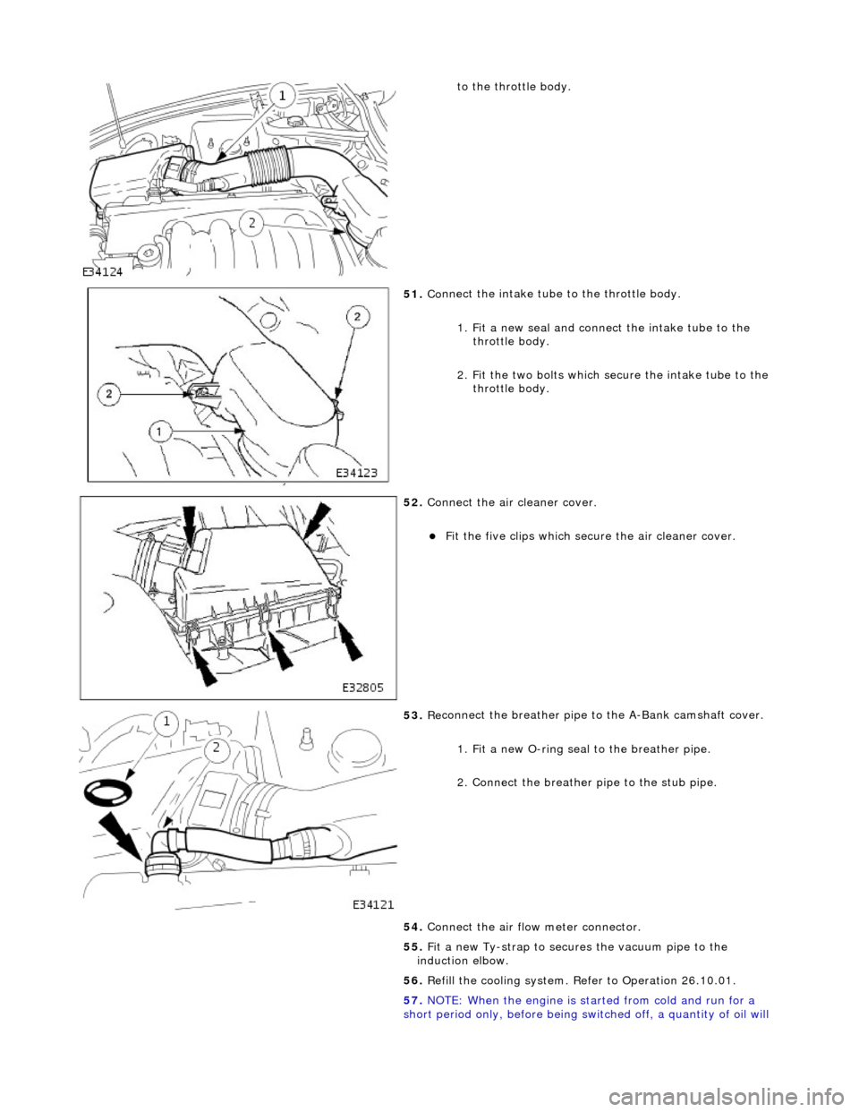
to th
e throttle body.
51 . Co
nnect the intake tube to the throttle body.
1. Fit a new seal and connect the intake tube to the throttle body.
2. Fit the two bolts which secure the intake tube to the throttle body.
52 . Conne
ct the air cleaner cover.
F
it
the five clips which secu
re the air cleaner cover.
53 . Re
connect the breather pipe to the A-Bank camshaft cover.
1. Fit a new O-ring seal to the breather pipe.
2. Connect the breather pipe to the stub pipe.
54. Connect the air flow meter connector.
55. Fit a new Ty-strap to secures the vacuum pipe to the
induction elbow.
56. Refill the cooling system. Refer to Operation 26.10.01.
57. NOTE: When the engine is star ted from cold and run for a
short period only, before being swit ched off, a quantity of oil will
Page 925 of 2490

T
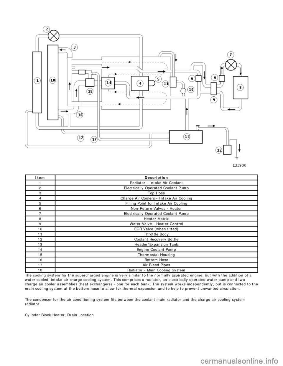
he cooling system for the supercharged engine is very similar
to the normally aspirated engine, but with the addition of a
water cooled, intake air charge cooling system. This comprises a radiator, an electrically operated water pump and two
charge air cooler assemblies (heat exchangers) - one for each bank. The system works independently, but is connected to the
main cooling system at the bottom hose to allow for therma l expansion and to help to prevent unwanted circulation.
The condenser for the air conditioning system fits between th e coolant main radiator and the charge air cooling system
radiator.
Cylinder Block Heater, Drain Location
ItemDe
scription
1Rad
iator - Intake Air Coolant
2Ele
ctrically Operated Coolant Pump
3Top Hose
4Charge Air Coo
lers -
Intake Air Cooling
5Fi
lling Point for Intake Air Cooling
6N
on-Return Valves - Heater
7Ele
ctrically Operated Coolant Pump
8Hea
ter Matrix
9Wate
r Valve - Heater Control
10EGR V
alve (when fitted)
11Thr
ottle Body
12Coolan
t Recovery Bottle
13H
eader/Expansion Tank
14Eng
ine Coolant Pump
15The
rmostat Housing
16Bottom
Hose
17Air Bleed
Pipes
18Rad
iator - Main Cooling System
Page 929 of 2490

The cooling
pack incorporates the radiator a
ssembly with integral transmission oil cool er (located in the radiator outlet tank),
an air conditioning condenser, and the cooling fans and cowl assembly.
The cooling pack on supercharged vehicles is the same as described above, but with the addition of a charge air cooler
coolant radiator located in front of the condenser.
Radiator Mounti
ng/Retention
T
he radiator is mounted on four rubber mounts, one on each
end of the upper and lower horizontal face. The two lower
mountings are supported on two isolated brackets mounted on the body; the lower cradle assembly has subsequently been
deleted.
A closing panel made from polypropylene, which retains the radiat or assembly, fits over the top of the radiator and is bolted
to the vehicle top panel.
Coolant Hoses - Engine
Page 937 of 2490

I
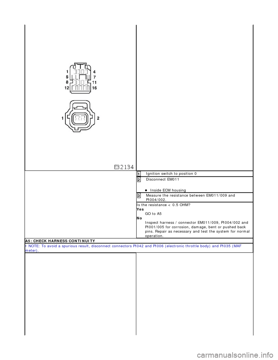
gnition switch to position 0
1
Di
sconnect EM011
Inside E
CM housing
2
Me
asure the resistance between EM011/009 and
PI004/002.
3
I
s the resistance < 0.5 OHM?
Yes GO to A5
No Inspect harness / connector EM011/009, PI004/002 and
PI001/005 for corrosion, damage , bent or pushed back
pins. Repair as necessary and test the system for normal
operation.
A5: CHECK
HARNESS CONTINUITY
•
NOTE: To avoid a spurious result, disconnect connectors PI042 and PI006 (electronic throttle body) and PI035 (MAF
meter).
Page 938 of 2490

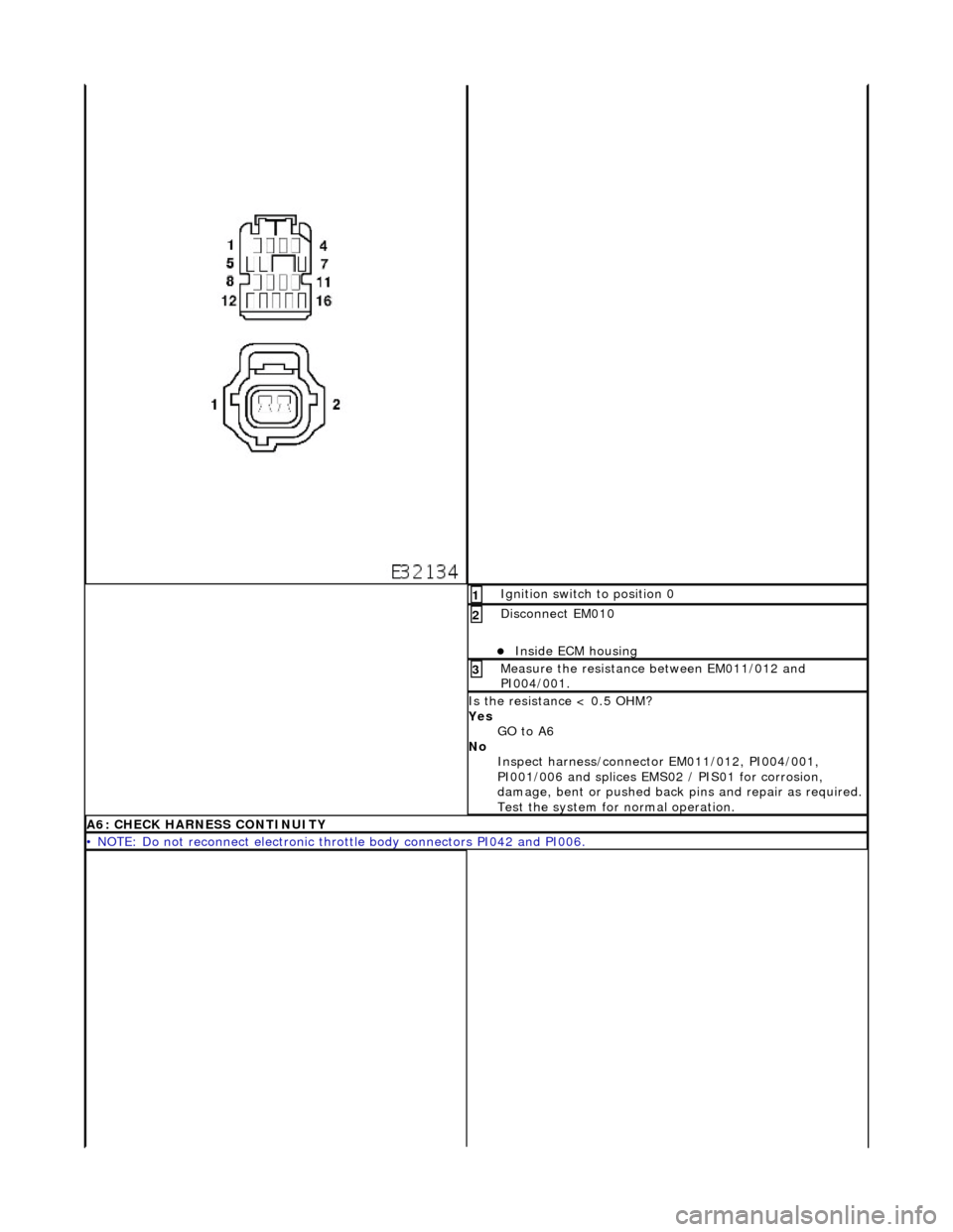
Ig
nition switch to position 0
1
Di
sc
onnect EM010
Inside E
C
M housing
2
Me
asure
the resistance between EM011/012 and
PI004/001.
3
I s
the resistance < 0.5 OHM?
Yes GO to A6
No Inspect harness/connector EM011/012, PI004/001,
PI001/006 and splices EMS02 / PIS01 for corrosion,
damage, bent or pushed back pins and repair as required.
Test the system for normal operation.
A6: CHECK HARNESS
CONTINUITY
•
NOTE
: Do not reconnect electronic thro
ttle body connectors PI042 and PI006.