body JAGUAR X308 1998 2.G Workshop Manual
[x] Cancel search | Manufacturer: JAGUAR, Model Year: 1998, Model line: X308, Model: JAGUAR X308 1998 2.GPages: 2490, PDF Size: 69.81 MB
Page 857 of 2490

Install and tighten the lower securing bolts to 18-24 Nm.
Tighten the upper securing bolts to 18-24 Nm.
16. Position the transmission cooler pipes and the clamping
bracket. Install the bolt to secu re the clamp and tighten to 7-9
Nm.
17. Connect the oil cooler pipes to the oil pan body assembly
(vehicles with engine oil cooler).
1. Remove the blanking plugs and install new O-ring seals.
2. Connect the oil cooler pipes.
3. Install the clamp and bolt which secures the oil cooler pipes. Tighten to 18-24 Nm.
18. Install the front cr ossmember. Refer to Operation 76.10.05.
19. Position the generator cooling duct to the oil pan body and
install the two bolts.
20. Install the undert ray. Refer to Operation 76.22.90.
21. Install both front wheel and tyre assemblies. Refer to
Operation 74.20.05.
22. Install the timing cover and al l associated components, as
detailed in Operation 12.65.01. Do not refill the cooling system
at this stage.
Page 862 of 2490

Engine - Valve Cover RH
In-vehicle Repair
Removal
1. Open the engine compartment and fit paintwork protection
sheets.
2. Disconnect the intake tube from the throttle body.
1. Remove the two bolts which secure the intake tube to the throttle body.
2. Disconnect the intake tube from the throttle body.
3. Disconnect the air cleaner cover.
Release the five clips which se cure the air cleaner cover.
4. Disconnect the air fl ow meter multi-plug.
5. Remove the intake tube / air flow meter / air cleaner cover
assembly.
1. Remove the intake tube / air flow meter / air cleaner
cover assembly.
2. Remove and discard the ru bber seal; air intake tube
to throttle body.
6. Carefully remove the right hand engine cover, taking care not
to damage the plastic fixi ngs or the rubber inserts.
7. Remove the on-plug ignition coils from the 'A' bank. Refer to
Operation 18.20.41.
8. Release the clips which secure the engine harness to the cam
cover.
Page 865 of 2490

6. Reposition the clips which secure the engine harness to the
cam cover.
7. Refit the on-plug ignition coils and the coil cover. Refer to
Operation 18.20.41.
8. Refit the right hand engine cover.
9. Fit the intake tube / air flow meter / air cleaner cover
assembly.
1. Fit a new rubber seal; air in take tube to throttle body.
2. Fit the intake tube / air flow meter / air cleaner cover
assembly.
10. Reconnect the air cleaner cover.
Fit the five clips which secu re the air cleaner cover.
11. Connect the intake tube to the throttle body.
1. Connect the intake tube to the throttle body.
Page 866 of 2490

2. Fit the two bolts which secure the intake tube to the throttle body.
12. Remove the paintwork protection sheets and close the engine
compartment.
Page 867 of 2490

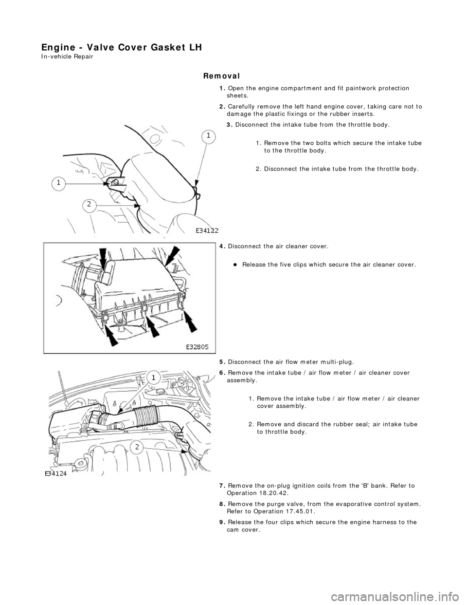
Engine - Valve Cover Gasket LH
In-vehicle Repair
Removal
1. Open the engine compartment and fit paintwork protection
sheets.
2. Carefully remove the le ft hand engine cover, taking care not to
damage the plasti c fixings or the rubber inserts.
3. Disconnect the intake tube from the throttle body.
1. Remove the two bolts which secure the intake tube to the throttle body.
2. Disconnect the intake tube from the throttle body.
4. Disconnect the air cleaner cover.
Release the five clips which se cure the air cleaner cover.
5. Disconnect the air fl ow meter multi-plug.
6. Remove the intake tube / air flow meter / air cleaner cover
assembly.
1. Remove the intake tube / air flow meter / air cleaner
cover assembly.
2. Remove and discard the ru bber seal; air intake tube
to throttle body.
7. Remove the on-plug ignition coils from the 'B' bank. Refer to
Operation 18.20.42.
8. Remove the purge valve, from th e evaporative control system.
Refer to Operation 17.45.01.
9. Release the four clips which secure the engine harness to the
cam cover.
Page 870 of 2490

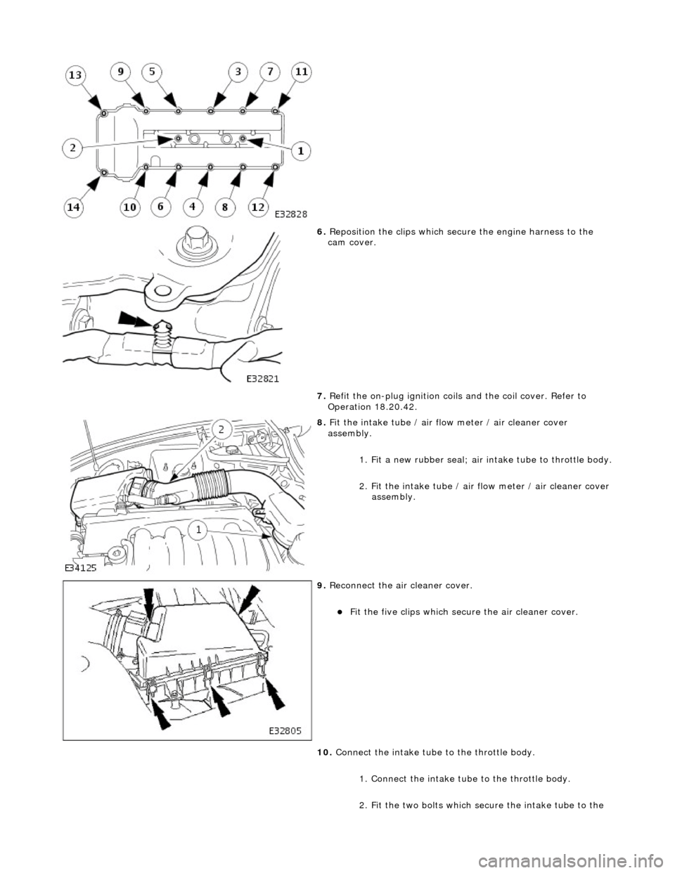
6. Reposition the clips which secure the engine harness to the
cam cover.
7. Refit the on-plug ignition coils and the coil cover. Refer to
Operation 18.20.42.
8. Fit the intake tube / air flow meter / air cleaner cover
assembly.
1. Fit a new rubber seal; air in take tube to throttle body.
2. Fit the intake tube / air flow meter / air cleaner cover
assembly.
9. Reconnect the air cleaner cover.
Fit the five clips which secu re the air cleaner cover.
10. Connect the intake tube to the throttle body.
1. Connect the intake tube to the throttle body.
2. Fit the two bolts which secure the intake tube to the
Page 871 of 2490

throttle body.
11. Refit the purge valve. Refer to Operation 17.45.01.
12. Reconnect the air flow meter multi-plug.
13. Refit the left hand engine cover.
14. Remove the paintwork protection sheets and close the engine
compartment.
Page 882 of 2490

Installation
20. Clean and inspect all relevant components.
1. Push the tensioner piston (secon dary chain) into the body to
provide clearance for fitting.
1. Insert a thin rigid wire th rough the hole in the end of
the tensioner piston to displace the ball from the non-
return valve seat.
2. With the wire in position, press the piston fully into the tensioner body.
Remove the wire.
2. Fit the VVT unit to the engine.
Assemble the VVT unit, the exhaust camshaft sprocket
and the secondary chain, in pr eparation for fitting to the
engine.
1. Fit the above assembly to the camshafts with the chain correctly positioned over the tensioner; VVT
unit to the inlet and the sprocket to the exhaust.
2. Fit, but do not tighten, each bolt which secures the VVT unit and the exhaust sprocket to the camshafts.
Allow the VVT unit sufficien t space to fit the primary
chain, in a la ter operation.
3. Fit the chain tensioning tool 303 - 532 to the exhaust camshaft
sprocket.
Reposition the sprocket (and the VVT unit) for the most
advantageous position for use of the tool.
Remove the tool.
4. Refit the primary timing chain.
1. Lift the primary chain an d position it over the VVT
unit sprocket (the VVT unit mu st be pulled forward to
clear the cylinder head casting). There must be no
slack on the drive side of the primary chain and the
VVT unit must not be rotated on the camshaft.
2. Slide the VVT unit fully on to the camshaft.
5. Fit the primary chain tensioner blade.
1. Position the tensioner blade to the cylinder block.
Page 887 of 2490

Installation
15. Remove the primary ch ain tensioner blade.
1. Remove the pivot bolt which secures the tensioner blade.
2. Remove the tensioner blade.
16. Disconnect the primary chain from the VVT unit and the
crankshaft sprocket, and remove it completely.
17. Do not tamper with the three bolts which secure the VVT
mechanism to the sprockets. It is sealed at the factory to the
correct valve timing specificatio n for the engine and is supplied
only as a complete unit.
18. Remove the VVT unit.
1. Remove the securing bolt from both the VVT unit and
the exhaust cam sprocket.
2. Remove the VVT unit, exhaust sprocket and secondary chain as an asse mbly (release the chain
from the tensioner which is still secured to the
cylinder head).
Remove the secondary chain from the VVT unit and the
sprocket.
19. Clean and inspect all relevant components.
1. Push the tensioner piston (secon dary chain) into the body to
provide clearance for fitting.
1. Insert a thin rigid wire th rough the hole in the end of
the tensioner piston to displace the ball from the non-
return valve seat.
2. With the wire in position, press the piston fully into the tensioner body.
Remove the wire.
2. Fit the VVT unit to the engine.
Assemble the VVT unit, the exhaust camshaft sprocket
and the secondary chain, in pr eparation for fitting to the
engine.
1. Fit the above assembly to the camshafts with the chain correctly positioned over the tensioner; VVT
unit to the inlet and the sprocket to the exhaust.
2. Fit, but do not tighten, each bolt which secures the VVT unit and the exhaust sprocket to the camshafts.
Page 898 of 2490

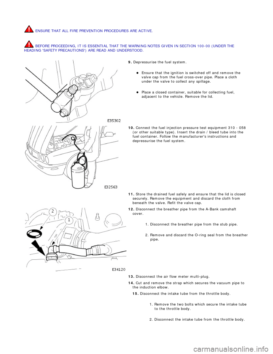
ENSURE THAT ALL FIRE PREVENTION PROCEDURES ARE ACTIVE.
BEFORE PROCEEDING, IT IS ESSENTIAL THAT THE WARNING NOTES GIVEN IN SECTION 100-00 (UNDER THE
HEADING 'SAFETY PRECAUTIONS') ARE READ AND UNDERSTOOD.
9. Depressurise the fuel system.
Ensure that the ignition is switched off and remove the
valve cap from the fuel cross-over pipe. Place a cloth
under the valve to collect any spillage.
Place a closed container, su itable for collecting fuel,
adjacent to the vehicle. Remove the lid.
10. Connect the fuel injection pressure test equipment 310 - 058
(or other suitable type). Insert the drain / bleed tube into the
fuel container. Follow the ma nufacturer's instructions and
depressurise the fuel system.
11. Store the drained fuel safely and ensure that the lid is closed
securely. Remove the equipmen t and discard the cloth from
beneath the valve. Refit the valve cap.
12. Disconnect the breather pipe from the A-Bank camshaft
cover.
1. Disconnect the breather pipe from the stub pipe.
2. Remove and discard the O-ring seal from the breather
pipe.
13. Disconnect the air flow meter multi-plug.
14. Cut and remove the strap which secures the vacuum pipe to
the induction elbow.
15. Disconnect the intake tube from the throttle body.
1. Remove the two bolts which secure the intake tube to the throttle body.
2. Disconnect the intake tube from the throttle body.