electrical JAGUAR X308 1998 2.G Workshop Manual
[x] Cancel search | Manufacturer: JAGUAR, Model Year: 1998, Model line: X308, Model: JAGUAR X308 1998 2.GPages: 2490, PDF Size: 69.81 MB
Page 1748 of 2490

Is the res
istance greater than 5 ohms?
Yes REPAIR the circuit. For additional information, refer to the wiring diagrams. CLEAR the DTC. TEST
the system for normal operation.
No GO to C10
.
C10: CHECK T H
E ECM TO CASSETTE REEL
CIRCUIT FOR CONTINUITY (CIRCUIT 2)
Measure t
he resistance between EM11,
pin 05 (SG) and SW01, pin 03 (SG).
1
Is the res
istance greater than 5 ohms?
Yes REPAIR the circuit. For additional information, refer to the wiring diagrams. CLEAR the DTC. TEST
the system for normal operation.
No Contact dealer technical support for advice on possible ECM failure.
PI
NPOINT TEST D : DTC P0
569; SPEED CONTROL DECEL/SET- SWITCH ON FAULT
WARN
ING: Where tests involve the removal of the steering
wheel, and/or disconnection of air bag connectors, the
procedure for disarming air bags must be followed,
REFER to: Air Bag Supplemental Re straint System (SRS)
(50
1-20B Supplemental Restra
int System, Description and
Operation).
TE S
T
CONDITIONS
D E
TAILS/RESULTS/ACTIONS
D1: CHECK
THE SPEED CONTROL SWITCHPACK IN
TERNAL CIRCUITS FOR SHORT TO GROUND
Disc
onnect the speed control switch
pack electrical connector, SW02.
1
Measure t
he resistance between SW
02, pin 06 (BO) and GROUND.
2
Measure t
he resistance between SW
02, pin 04 (SR) and GROUND.
3
Is either resistance le
ss than 10,000 ohms?
Yes REPAIR the short circuit. For addi tional information, refer to the wiring diagrams. CLEAR the DTC.
TEST the system for normal operation.
No GO to D2
.
D2: CHECK
THE SPEED CONTROL CASSE
TTE REEL FOR SHORT TO GROUND
Me
asure the resistance between SW02, pin 06 (at the cassette reel side of the connector) and
GROUND.
1
M e
asure the resistance between SW02, pin 04 (at the cassette reel side of the connector) and
GROUND.
2
Is either resi stance le
ss than 10,000 ohms?
Yes REPAIR the short circuit. For addi tional information, refer to the wiring diagrams. CLEAR the DTC.
TEST the system for normal operation.
No GO to D3
.
D3: CHECK
THE SPEED CONTROL DECEL/SET- SWITCH ACTION
Meas
ure t
he resistance between SW02,
pin 06 (BO) and SW02, pin 04 (SR).
1
Operate
the speed control
DECEL/SET- switch.
2
Do
es the resistance
vary by 680 ohms?
Yes Recheck DTCs. No short found. Po ssible intermittent fault. CLEAR the DTC. TEST the system for
normal operation.
No INSTALL a new speed control switchpack. CLEAR the DTC. TEST the system for normal operation.
PINPOI
NT TEST E : DTC P0570; SPEED CONTROL "ACCEL/SET+" SWITCH "ON" FAULT
WAR
N
ING: Where tests involve the removal of the steering
wheel, and/or disconnection of air bag connectors, the
procedure for disarming air bags must be followed,
REFER to: Air Bag Supplemental Re straint System (SRS)
(50
1-20B Supplemental Restra
int System, Description and
Operation).
TE S
T
CONDITIONS
D E
TAILS/RESULTS/ACTIONS
E1
: CHECK THE SPEED CONTROL
SWITCHPACK IN
TERNAL CIRCUITS FOR SHORT TO GROUND
Page 1749 of 2490
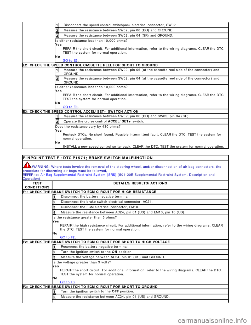
Di
sconnect the speed control switch
pack electrical connector, SW02.
1
Meas
ure the resistance between SW
02, pin 06 (BO) and GROUND.
2
Meas
ure the resistance between SW
02, pin 04 (SR) and GROUND.
3
Is either resi
stance
less than 10,000 ohms?
Yes REPAIR the short circuit. For addi tional information, refer to the wiring diagrams. CLEAR the DTC.
TEST the system for normal operation.
No GO to E2
.
E2
: CHECK THE SPEED CONTROL CASSE
TTE REEL FOR SHORT TO GROUND
M
easure the resistance between SW02, pin 06 (at the cassette reel side of the connector) and
GROUND.
1
M
easure the resistance between SW02, pin 04 (at the cassette reel side of the connector) and
GROUND.
2
Is either resi
stance
less than 10,000 ohms?
Yes REPAIR the short circuit. For addi tional information, refer to the wiring diagrams. CLEAR the DTC.
TEST the system for normal operation.
No GO to E3
.
E3
: CHECK THE SPEED CONTROL
ACCEL/SET+ SWITCH ACTION
Meas
ure the resistance between SW02,
pin 06 (BO) and SW02, pin 04 (SR).
1
Op
erate the cruise control
ACCEL/SET+ switch.
2
D
oes the resistance
vary by 430 ohms?
Yes Recheck DTCs. No short found. Po ssible intermittent fault. CLEAR the DTC. TEST the system for
normal operation.
No INSTALL a new speed control switchpack. CLEAR the DTC. TEST the system for normal operation.
P
INPOINT TEST F : DTC P1571;
BRAKE SWITCH MALFUNCTION
WAR
NING: Where tests involve the removal of the steering
wheel, and/or disconnection of air bag connectors, the
procedure for disarming air bags must be followed,
REFER to: Air Bag Supplemental Re straint System (SRS)
(501-20B Supplemental Restra
int System, Description and
Operation).
TE
ST
CONDITIONS
D
ETAILS/RESULTS/ACTIONS
F1: CHECK THE BRAKE
SWITCH TO
ECM CIRCUIT FOR HIGH RESISTANCE
Di
sconnect the battery negative terminal.
1
Di
sconnect the brake switch electrical connector, AC24.
2
D
isconnect the ECM electrical connector, EM10.
3
Meas
ure the resistance between AC24,
pin 01 (US) and EM10, pin 10 (US).
4
Is th
e resistance greater than 5 ohms?
Yes REPAIR the high resistance circui t. For additional information, refer to the wiring diagrams. CLEAR
the DTC. TEST the system for normal operation.
No GO to F2
.
F2: CHECK THE BRAKE
SWITCH TO ECM
CIRCUIT FOR SHORT TO HIGH VOLTAGE
R
econnect the battery negative terminal.
1
Turn the ignition swi
tch to the ON
position.
2
M
easure the voltage between AC24, pin 01 (US) and GROUND.
3
Is th
e voltage greater than 3 volts?
Yes REPAIR the short circuit. For addi tional information, refer to the wiring diagrams. CLEAR the DTC.
TEST the system for normal operation.
No GO to F3
.
F3: CHECK THE BRAKE
SWITCH TO
ECM CIRCUIT FOR SHORT TO GROUND
Turn the ignition swi
tch to the OFF
position.
1
Meas
ure the resistance between AC24, pin 01 (US) and GROUND.
2
Page 1750 of 2490
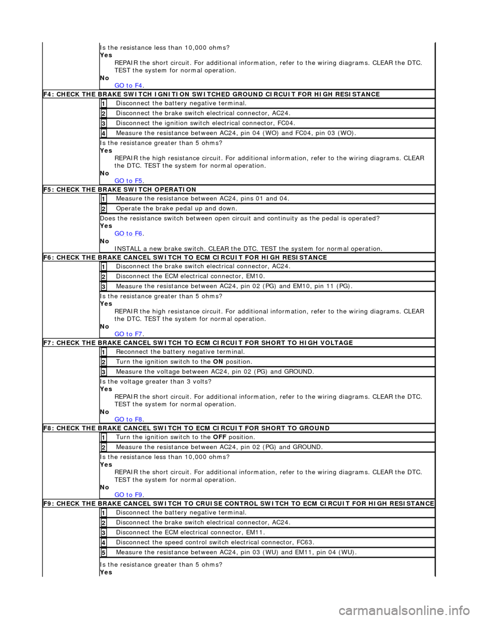
Is t
he resistance less than 10,000 ohms?
Yes REPAIR the short circuit. For addi tional information, refer to the wiring diagrams. CLEAR the DTC.
TEST the system for normal operation.
No GO to F4
.
F4: CHECK THE BRAKE SWITCH IGNITION SWIT
C
HED GROUND CIRCUIT FOR HIGH RESISTANCE
Di
sc
onnect the battery negative terminal.
1
Di
sc
onnect the brake switch electrical connector, AC24.
2
Di
sc
onnect the ignition switch electrical connector, FC04.
3
Measure t
he resistance between AC24,
pin 04 (WO) and FC04, pin 03 (WO).
4
Is the res
istance greater than 5 ohms?
Yes REPAIR the high resistance circui t. For additional information, refer to the wiring diagrams. CLEAR
the DTC. TEST the system for normal operation.
No GO to F5
.
F5: CHECK THE BRAKE SWITCH O
PERATION
Me
asure
the resistance between AC24, pins 01 and 04.
1
O
p
erate the brake pedal up and down.
2
Doe
s
the resistance switch between open circuit and continuity as the pedal is operated?
Yes GO to F6
.
No
INST
ALL a new brake switch. CLEAR the DTC.
TEST the system for normal operation.
F6: CHECK THE BRAKE CANCEL
SWITCH
TO ECM CIRCUIT FOR HIGH RESISTANCE
Disc
onnect the brake switch electrical connector, AC24.
1
D
i
sconnect the ECM electrical connector, EM10.
2
Me
asure
the resistance between AC24, pin 02 (PG) and EM10, pin 11 (PG).
3
Is th
e res
istance greater than 5 ohms?
Yes REPAIR the high resistance circui t. For additional information, refer to the wiring diagrams. CLEAR
the DTC. TEST the system for normal operation.
No GO to F7
.
F7: CHECK THE BRAKE CANCEL
SWITCH TO
ECM CIRCUIT FOR SHORT TO HIGH VOLTAGE
Re
connect the battery negative terminal.
1
Turn the ignition swi
t
ch to the ON
position.
2
Me
asure the voltage between AC24, pin 02 (PG) and GROUND.
3
Is th
e volt
age greater than 3 volts?
Yes REPAIR the short circuit. For addi tional information, refer to the wiring diagrams. CLEAR the DTC.
TEST the system for normal operation.
No GO to F8
.
F8: CHECK THE BRAKE CANCEL
SWITCH
TO ECM CIRCUIT FO R SHORT TO GROUND
Turn the ignition swit
ch to the OFF
position.
1
Measure t
he resistance between AC24, pin 02 (PG) and GROUND.
2
Is
t
he resistance less than 10,000 ohms?
Yes REPAIR the short circuit. For addi tional information, refer to the wiring diagrams. CLEAR the DTC.
TEST the system for normal operation.
No GO to F9
.
F9: CHECK THE BRAKE CANCEL
SWITCH
TO CRUISE CONTROL SWITCH TO ECM CIRCUIT FOR HIGH RESISTANCE
Disc
onnect the battery negative terminal.
1
Di
sc
onnect the brake switch electrical connector, AC24.
2
D
i
sconnect the ECM electrical connector, EM11.
3
Di
sc
onnect the speed control switch electrical connector, FC63.
4
Me
asure
the resistance between AC24, pin 03 (WU) and EM11, pin 04 (WU).
5
Is th
e res
istance greater than 5 ohms?
Yes
Page 1760 of 2490
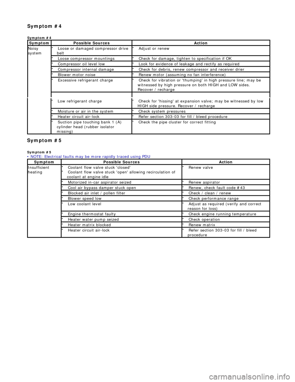
Symp
tom #5
Sy
m
ptom #5
Low r
e
frigerant charge
*
Check f or 'hissi
ng' at expansion
valve; may be witnessed by low
HIGH side pressure. Recover / recharge
*
Moi
s
ture or air in the system
*
Chec k syst
em pressures
*
Heat er ci
rcuit air-lock
*
R e
fer section 303-03 for fill / bleed procedure
*
Suct ion
pipe touching bank 1 (A)
cylinder head (rubber isolator
missing)
*
Check the pi
pe cluster for correct fitti
ng
*
• NOTE: Electrical faults may be more rapidly traced using PDU
Sym
ptom
Possib
l
e Sources
Acti
o
n
Insuffi
ci
ent
heating
Coo l
ant flow valve stuck 'closed'
Coolant flow valve stuck 'open' allowing recirculation of
coolant at engine idle
*
*
Re
new v
alve
*
Motorized in-car aspirator sei zed
*R e
new aspirator
*
Coo l
air bypass damper stuck open
*
Re new,
check fault code #43
*
B l
ocked air inlet / pollen filter
*
Chec k / cl
ean / renew
*
B l
ower speed low
*
Check performance range
*
Low cool ant
level
*
Adjust as req u
ired (verify and correct
reason for loss)
*
Engine
t
hermostat faulty
*
Check engine r u
nning temperature
*
Heater water pump seized
*Chec k op
eration
*
Heater ma trix
blocked
*
Re new m
atrix
*
Heater circui t
air-lock
*
R e
fer section 303-03 for fill / bleed
procedure
*
Sym
p
tom #4
Sym
ptom #4
Sy
m
ptom
Possib
l
e Sources
Acti
o
n
No
i
sy
system
Loose or damaged compressor drive
belt
*Adjust or r
e
new
*
Loose compressor mountings
*Check f o
r damage, tighten to specification if OK
*
Compressor oil level l
ow
*
Look for evidence of l
eakag
e and rectify as required
*
Compressor internal dama ge
*Check f o
r debris, renew compressor and receiver drier
*
B l
ower motor noise
*
Re new m
otor (assuming no fan interference)
*
Excessive refrige rant charge
*Check f o
r vibration or 'thumping'
in high pressure line; may be
witnessed by high pressure on both HIGH and LOW sides.
Recover / recharge
*
Page 1784 of 2490
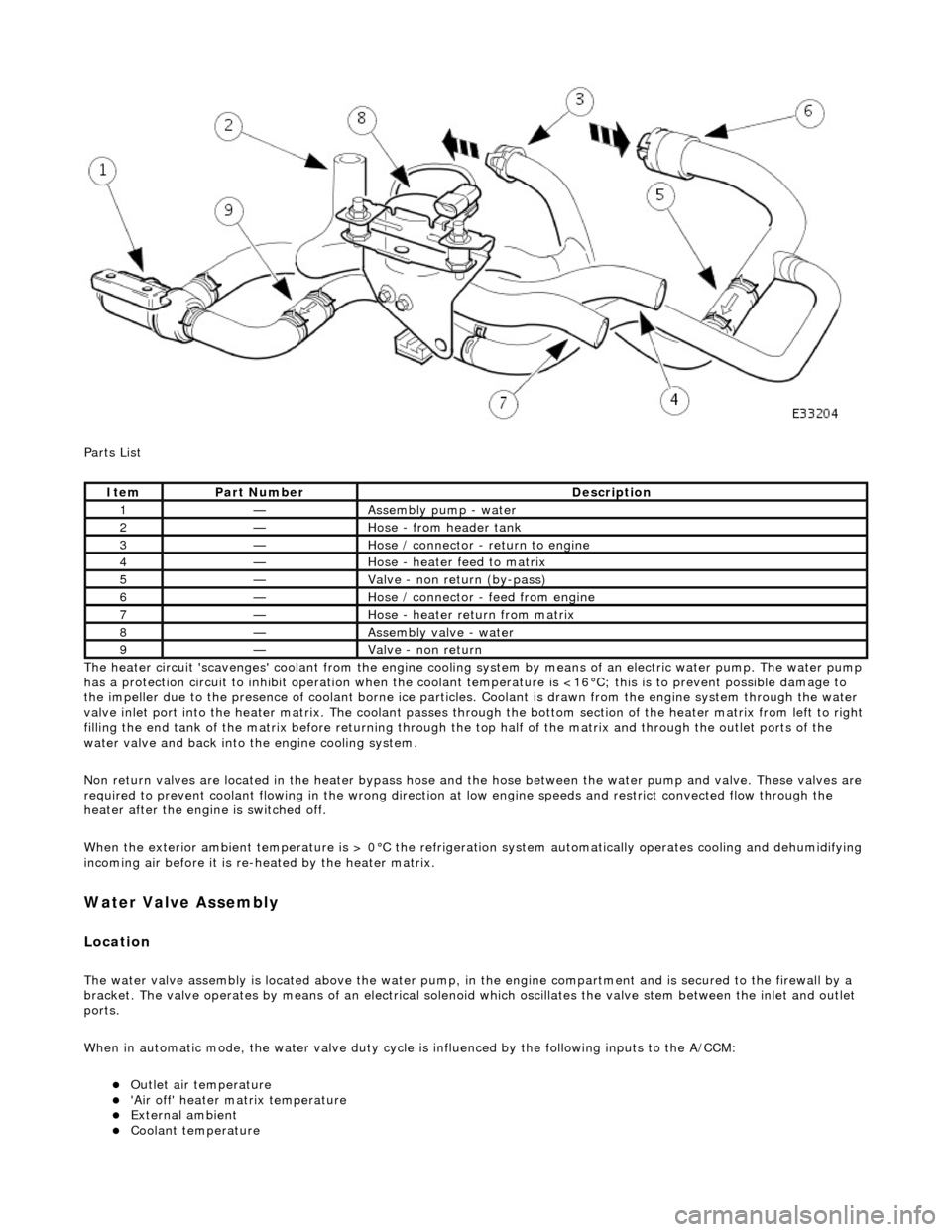
Parts List
The heater circuit 'scavenges' coolant from the engine cooling system by mean s of an electric water pump. The water pump
has a protection circuit to inhibit operation when the coolant temperature is <16В°C; this is to prevent possible damage to
the impeller due to the presence of coolant borne ice particles. Coolant is drawn from the en gine system through the water
valve inlet port into the heater matrix. The coolant passes thro ugh the bottom section of the heater matrix from left to right
filling the end tank of the matrix before returning through the top half of the ma trix and through the outlet ports of the
water valve and back into the engine cooling system.
Non return valves are located in the heat er bypass hose and the hose between the water pump and valve. These valves are
required to prevent coolant flowing in th e wrong direction at low engine speeds and restrict convected flow through the
heater after the engine is switched off.
When the exterior ambient temperature is > 0В°C the refrigerat ion system automatically operates cooling and dehumidifying
incoming air before it is re -heated by the heater matrix.
Water Valve Assembly
Location
The water valve assembly is located above the water pump, in the engine compartmen t and is secured to the firewall by a
bracket. The valve operates by means of an electrical solenoid which oscillates the valve stem between the inlet and outlet
ports.
When in automatic mode, the water valve duty cycle is influenced by the following inputs to the A/CCM:
пЃ¬Outlet air temperature пЃ¬'Air off' heater matrix temperature пЃ¬External ambient пЃ¬Coolant temperature
ItemPart NumberDescription
1—Assembly pump - water
2—Hose - from header tank
3—Hose / connector - return to engine
4—Hose - heater feed to matrix
5—Valve - non return (by-pass)
6—Hose / connector - feed from engine
7—Hose - heater return from matrix
8—Assembly valve - water
9—Valve - non return
Page 1790 of 2490
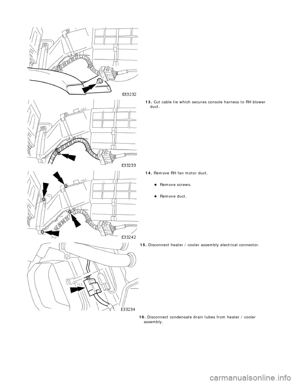
13. Cut cable tie which secures console harness to RH blower
duct.
14. Remove RH fan motor duct.
пЃ¬Remove screws.
пЃ¬Remove duct.
15. Disconnect heater / cooler assembly electrical connector.
16. Disconnect condensate drain tubes from heater / cooler
assembly.
Page 1794 of 2490

7. Position LH rear footwell inte rmediate duct to rear duct.
пЃ¬Secure with suitable cloth tape.
8. Connect heater / cooler assembly electrical connector.
9. Install LH fan motor duct.
пЃ¬Install duct.
пЃ¬Install screws.
10. Install cable tie to secure console harness to LH blower duct.
Page 1823 of 2490
8.8. Automatic
Symbol indicates when the control of , temperature, fan speed and air distribution are all in Auto mode.
9. 9. External
There are two modes of external ambient temperature selection;
пЃ¬Quick Display. Pressing the button for <1.5 seconds (con firmed by a single bleep) will display the external
temperature for 4 seconds.
пЃ¬Continuous Display. Pressing and holding the button fo r >1.5 seconds (confirmed by two beeps) displays the
external ambient temperature continuously, the value of which will be updated every 4 seconds given that vehicle
road speed is > 25 km/h. Pressing the button again fo r <1.5 seconds resets to the previous display.
• NOTE: Continuous external temperature display will be cancel led when the ignition is switched OFF but not during engine
cranking.
10. 10. A/C
This push-on / push-off button will either select or deselect (as indicated by the state lamp) the refrigeration system.
The refrigeration system is automatically engaged when the Auto button is pressed.
• NOTE: Interior misting of screens may be reduced by continuous operation of th e refrigeration system.
11. 11. Auto
When selected and the state lamp lit, A/C mode will be operat ional and control of vent outlet temperature, fans speed and
air distribution will be automatic.
AUTO mode will disengage should manual air distribution or defrost buttons be operated or the manual fan speed knob be
rotated.
• NOTE: Automatic temperature control is constantly main tained irrespective of selected manual overrides.
12. 12. Defrost
Push-on push-off button, which when engaged will direct all air to the front and side glass at maximum fan speed. The
heated windshield (if fitted) will also be energized for a timed cycle of 6,5 minute s, but may be cancelled by pressing the
HEATED WINDSHIELD (F) button. Pressing 'DEF' again will retu rn to the last setting with automatic temperature control
being maintained.
Directing warm and humid air onto a cold screen can produce interior misting of screens. Operating the climate control
system without the refrigerati on system operating will exacerbate this problem.
• NOTE: Directing cold air onto the screen in warm humid conditions can produce external condensation.
13. 13. Heated Windshield (F)
Pressing the heated windshield button (whe re fitted) will energize the electrically heated windshield elements for a timed
cycle of 6,5 minutes; pressing the button again will cancel the request. Should the engine stall or the ignition be turned
OFF, the timer will be cleare d and the function cancelled.
• NOTE: The heated windshield may be activated with the cl imate control system OFF but the engine must be running.
In very cold ambient temperatures, icing of the interior of the glass is possible when the climate control system is operating
in AUTO mode; to reduce this poss ibility the A/CCM provides automatic operation of the heated windshield.
With the following conditions met, the heated windshield will automatically energize but the state lamp will NOT be lit.
Page 1829 of 2490

The solar sensor is mounted on the top surface of the fascia between the defrost outlets.
The sensor is a photo-diode which is calibr ated to measure direct sunlight. It provides an output signal to the A/CCM which
automatically reduces air temperature an d increases fan speed (airflow volume) to compensate for solar heating.
Evaporator Sensor
This thermistor device changes electrical resistance as a result of temperature variations.
The sensor is positioned next to the evaporator fins and measures air temper ature after it has passed through the
evaporator. The sensor inputs a signal to the A/CCM which controls the compress or (see table) when the refrigeration
system is operating.
The sensor's connector is located on the LH side of the air conditioning unit, in front of the main power connector.
The A/CCM disengages the compressor clutch when the temperature of the air off the evaporator is 2В° C or less. This is to
prevent the moisture which may collect between the cooling fins of the evaporator from freezing and thus restricting airflow.
Heater Matrix Temperature Sensor
Evaporator Temperature SignalCompressor State
3В°CON - clutch engaged
2В°COFF - clutch disengaged
Page 1830 of 2490
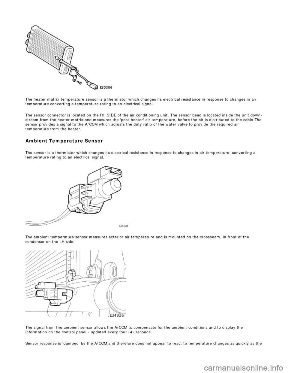
The heater matrix temperature sensor is a thermistor which changes its electrical resistance in response to changes in air
temperature converting a temperature rating to an electrical signal.
The sensor connector is located on the RH SIDE of the air conditioning unit. The sensor bead is located inside the unit down-
stream from the heater matrix and measures the 'post-heater' air temperature, before the air is distribu ted to the cabin The
sensor provides a signal to the A/CCM which adjusts the duty ratio of the water valve to provide the required air
temperature from the heater.
Ambient Temperature Sensor
The sensor is a thermistor which changes its electrical resistance in response to changes in air temperature, converting a
temperature rating to an electrical signal.
The ambient temperature sensor measures exterior air temper ature and is mounted on the crossbeam, in front of the
condenser on the LH side.
The signal from the ambient sensor allo ws the A/CCM to compensate for the ambient conditions and to display the
information on the control panel - updated every four (4) seconds.
Sensor response is 'damped' by the A/CCM and ther efore does not appear to react to temperature chan
ges as quickly as the