electrical JAGUAR X308 1998 2.G Workshop Manual
[x] Cancel search | Manufacturer: JAGUAR, Model Year: 1998, Model line: X308, Model: JAGUAR X308 1998 2.GPages: 2490, PDF Size: 69.81 MB
Page 2205 of 2490
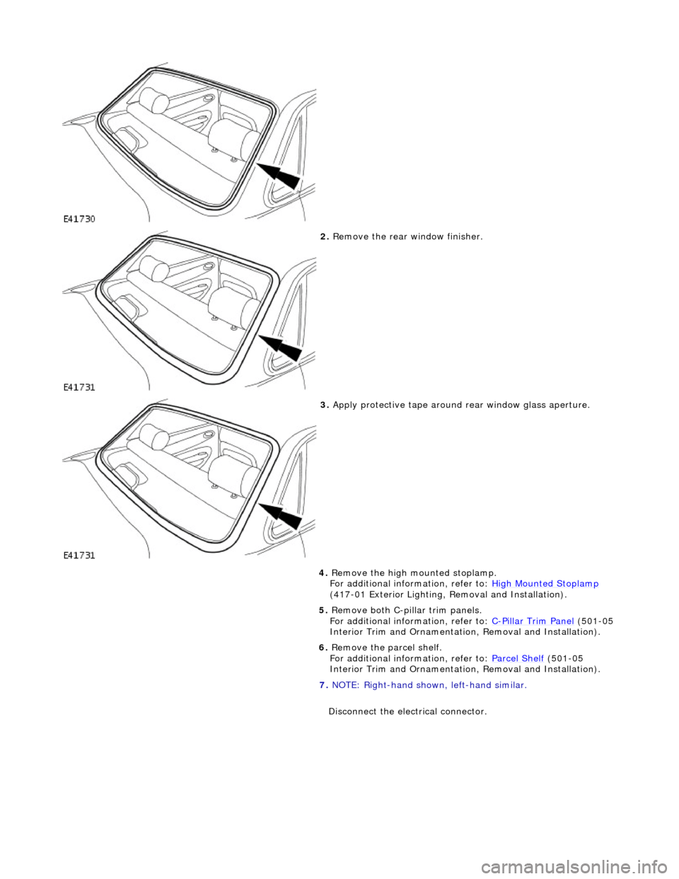
2. Remove the rear window finisher.
3. Apply protective tape around rear window glass aperture.
4. Remove the high mounted stoplamp.
For additional information, refer to: High Mounted Stoplamp
(417-01 Exterior Lighting, Removal and Installation).
5. Remove both C-pill ar trim panels.
For additional information, refer to: C
-Pillar Trim Panel (501-05
Interior Trim and Ornamentatio n, Removal and Installation).
6. Remove the parcel shelf.
For additional information, refer to: Parcel Shelf
(501-05
Interior Trim and Ornamentatio n, Removal and Installation).
7. NOTE: Right-hand shown, left-hand similar.
Disconnect the electrical connector.
Page 2206 of 2490
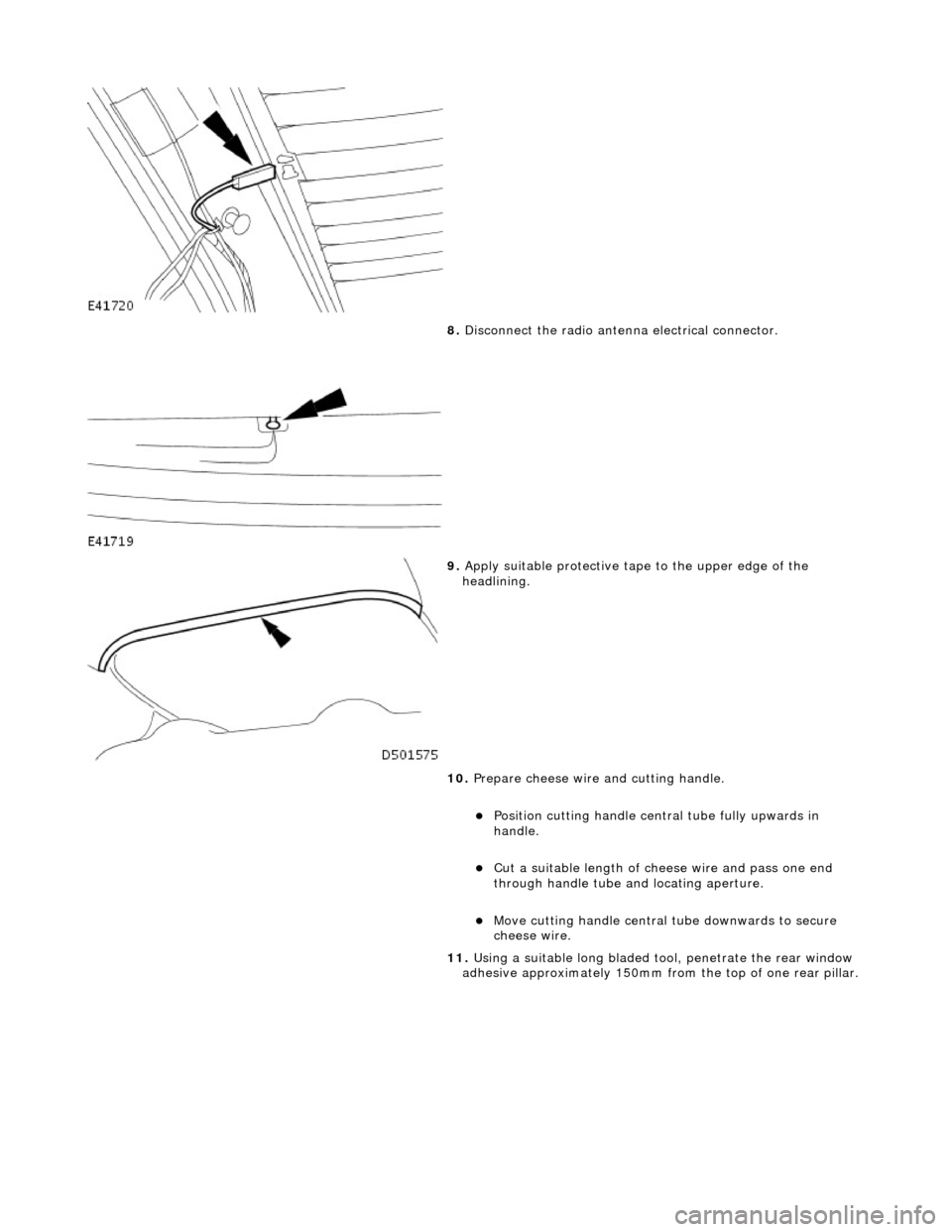
8. Disconnect the radio antenn a electrical connector.
9. Apply suitable protec tive tape to the upper edge of the
headlining.
10. Prepare cheese wire and cutting handle.
пЃ¬Position cutting handle cent ral tube fully upwards in
handle.
пЃ¬Cut a suitable length of ch eese wire and pass one end
through handle tube and locating aperture.
пЃ¬Move cutting handle central tube downwards to secure
cheese wire.
11. Using a suitable long bladed tool, penetrate the rear window
adhesive approximately 150mm fro m the top of one rear pillar.
Page 2210 of 2490
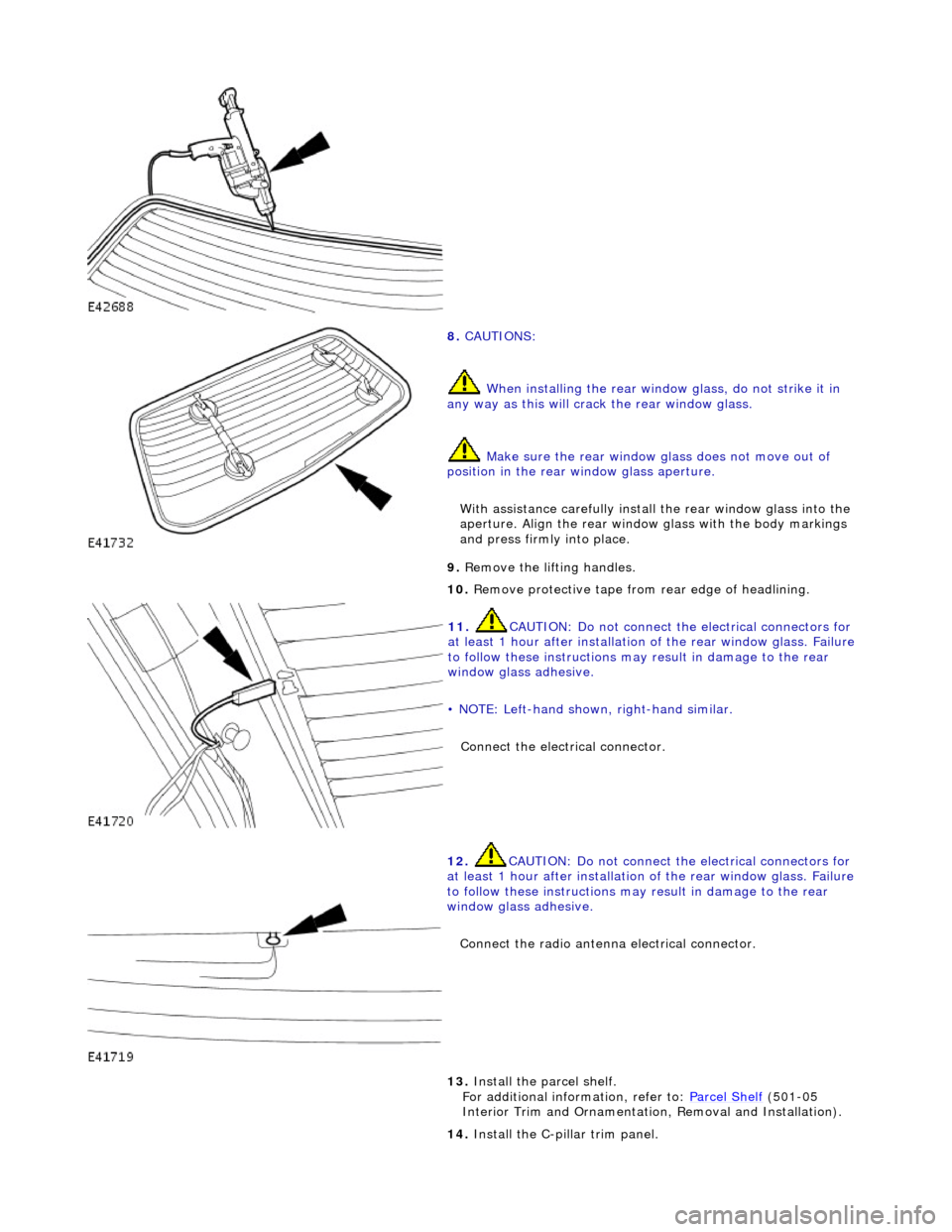
8. CAUTIONS:
When installing the rear window glass, do not strike it in
any way as this will crac k the rear window glass.
Make sure the rear window glass does not move out of
position in the rear window glass aperture.
With assistance carefully install the rear window glass into the
aperture. Align the rear window glass with the body markings
and press firmly into place.
9. Remove the lifting handles.
10. Remove protective tape from rear edge of headlining.
11. CAUTION: Do not connect the electrical connectors for
at least 1 hour after installation of the rear window glass. Failure
to follow these instructions may result in damage to the rear
window glass adhesive.
• NOTE: Left-hand shown, right-hand similar.
Connect the electrical connector.
12. CAUTION: Do not connect the electrical connectors for
at least 1 hour after installation of the rear window glass. Failure
to follow these instructions may result in damage to the rear
window glass adhesive.
Connect the radio antenna electrical connector.
13. Install the parcel shelf.
For additional information, refer to: Parcel Shelf (501-05
Interior Trim and Ornamentatio n, Removal and Installation).
14. Install the C-pillar trim panel.
Page 2277 of 2490
Handles, Locks, Latches and Entry Systems - Exterior Driver Door Handle
Removal and Installation
Removal
1. Motor door glass to fully up position.
2. Remove battery cover and disconnect ground cable from
battery terminal. Refer to 86.15.19.
3. Remove door casing veneer panel. Refer to 76.47.11.
4. Remove door casing for access. Refer to 76.34.01.
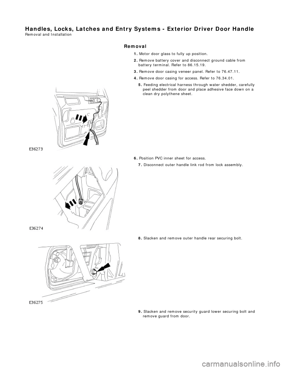
5. Feeding electrical harness thro ugh water shedder, carefully
peel shedder from door and pl ace adhesive face down on a
clean dry polythene sheet.
6. Position PVC inner sheet for access.
7. Disconnect outer handle link rod from lock assembly.
8. Slacken and remove outer handle rear securing bolt.
9. Slacken and remove security gu ard lower securing bolt and
remove guard from door.
Page 2297 of 2490
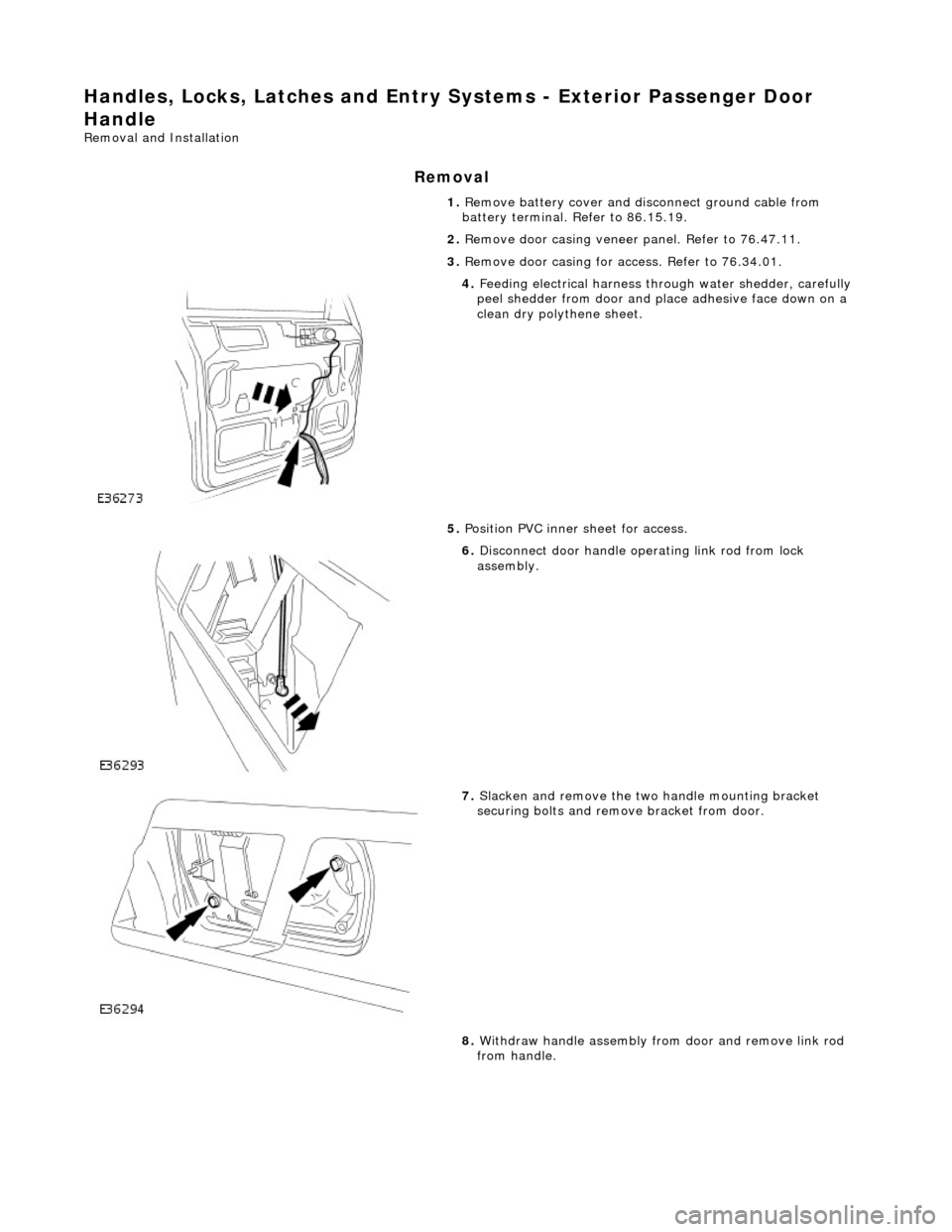
Handles, Locks, Latches and Entry Systems - Exterior Passenger Door
Handle
Removal and Installation
Removal
1. Remove battery cover and disconnect ground cable from
battery terminal. Refer to 86.15.19.
2. Remove door casing veneer panel. Refer to 76.47.11.
3. Remove door casing for access. Refer to 76.34.01.
4. Feeding electrical harness thro ugh water shedder, carefully
peel shedder from door and pl ace adhesive face down on a
clean dry polythene sheet.
5. Position PVC inner sheet for access.
6. Disconnect door handle operating link rod from lock
assembly.
7. Slacken and remove the two handle mounting bracket
securing bolts and remove bracket from door.
8. Withdraw handle assembly from door and remove link rod
from handle.
Page 2328 of 2490
Roof Opening Panel - Roof Opening Panel
Description and Operation
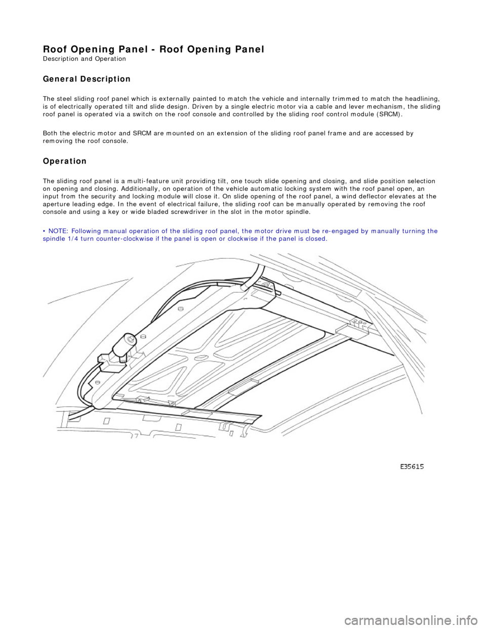
General Description
The steel sliding roof panel which is externally painted to ma tch the vehicle and internally trimmed to match the headlining,
is of electrically operated tilt and slide design. Driven by a single electric motor via a cable and lever mechanism, the slidi ng
roof panel is operated via a switch on the roof console and controlled by the sliding roof control module (SRCM).
Both the electric motor and SRCM are mounted on an extens ion of the sliding roof panel frame and are accessed by
removing the roof console.
Operation
The sliding roof panel is a multi-feature unit providing tilt, one touch slide opening and closing, and slide position selectio n
on opening and closing. Additi onally, on operation of the vehicle automatic locking system with the roof panel open, an
input from the security and lockin g module will close it. On slide opening of the roof panel, a wind deflector elevates at the
aperture leading edge. In the event of electrical failure, the sliding roof can be manually operated by removing the roof
console and using a key or wide bladed scre wdriver in the slot in the motor spindle.
• NOTE: Following manual operation of the sliding roof panel, the motor drive must be re-engaged by manually turning the
spindle 1/4 turn counter-clockwise if the panel is open or clockwise if the panel is closed.
Page 2383 of 2490
Paint
The inhalation of sprays, fumes, or dust during paint application or sanding processes should always be avoided. Ensure
that there is efficient ventilation / extrac tion at all times. Paint spraying should be confined as far as possible to spray
booths. Personnel with a history of asth ma should not be employed in any process involving the use of isocyanates.
Operators working in a spray booth where isocyanate material is present must use air-fed breathing equipment with air
supplied to the visor at the re commended pressure and filtered to remove oil, water, and fumes. Operators involved in
handling mixing or spraying should wear protective clothing including gloves and goggles, to avoid skin and eye contact.
Particle masks or canister type respir atosr should be worn when sanding.
Applied Heat
When welding, flame cutting, brazing etc, the operator shou ld use as appropriate, goggles, mask / fume extractor and
flameproof protective clothing. It is especially important when working with polyurethane compounds to use air-fed
breathing equipment. Appropriat e fire fighting equipment and personnel trai ned in its use must always be available.
Metal Repair
Appropriate eye and hand protection should be worn when sanding, drilling, cutting, chiselling, flatting or welding. Face
masks or air-fed visors should also be wo rn when sanding or flatting either body solder or fillers. On completion of a
soldering operation, swarf must be re moved from the work area and the operat or must wash his hands thoroughly.
GENERAL REPAIR NOTES
The following advice should be noted before any repair work is carried out.
Disconnect the vehicle battery gr ound lead (disconnect the alternator where electric welding is used) and take note of the
reconnection procedures as detailed in 86.15.15.
Where structural parts are straightened or renewed, a body alignment / straightening jig must be used. The application of
heat, especially excessive heat, reduces the strength of steels, where appropriate therefore, structural sections should be
straightened by cold processes.
Repairs may only be carried out successful ly, and any warranties protected, if genuine Jaguar replacement parts and Jaguar
approved materials are used.
The correct tools, procedures and facilities must always be us ed. The quality of the work must not be compromised by using
inappropriate methods or equipment.
All trim and electrical components in the locality of the repair must be removed or disconnected prior to panel removal /
replacement; this is especially important where hollow sectio ns may contain harnesses, tubes or foam, see section A4.3.5.
WARNING: DO NOT WORK IN THE VICINITY OF A LIVE AIR BAG, REMOVE IT COMPLETELY. READ WORKING
PRACTICES AIR BAG, SECTION 20. ANY SEAT BELT WHICH HAS BEEN WORN IN AN ACCIDENT MUST BE RENEWED.
CAUTION: Electric arc welding should not be used on Jaguar vehicles. The high voltages produced by this process will
cause irreparable damage to the electric al control and microprocessor systems.
The following welding and gas processes are the only ones recommended by Jaguar Cars Ltd.
Welding and Gas Processes
Resistance spot welding, MIG welding and all gas processes may only be carried out on bare, unpainted or unplated metal.
The flanges of panels to be welded toge ther, must be clean, corrosion free and tr eated as appropriate, with either weld-
through primer or inter-weld sealer. Only materials and processes specified in the 'Body Sealing and Preservation Manual'
should be used in the relevant application areas detailed in this section. Refer to 'Zinc Coated Panels' Section
Page 2391 of 2490
ZINC COATED PANELS
Description
Approximately 70% of the 'body in white' (BIW) mass is made up of zinc coated panels.
• NOTE: To maintain the protective qualities of the zinc trea tment, repairs to any damaged coated area must be made as
soon as possible after the damage has occurred.
All exterior skin panels, with the exceptio n of the roof, are double side zinc plated and this coating (nominally 7,5 microns)
provides two way corrosion protection. Should the outer layer of paint become chipped with the zinc coating remain intact,
the zinc will oxidize on contact with air and being impermeable, this coat of oxidation will prevent corrosion damage of the
base metal. If the outer layer of paint and the zinc coating become damaged, the zinc rather than the base metal will react
with the air and 'sacrifice' itself to corrosion as a 'sacrificial anode'.
Welding Preparation
Contamination of the weld with resultant reduction in joint st rength increase and increased electrode tip dressing frequency
will occur zinc coating is not removed. In exceptional cases where the zinc coating must remain intact, the tip pressure and
welding current should be increased by 10 to 20%.
Where 'resistance spot welding' is employed, the zinc coatin g should be lightly abraded away on the mating surfaces and
those in contact with the electrode tips. Do not remove more zinc coating than is absolutely necessary.
Before welding, a weld-through primer or inter-weld sealer should be applied, as detailed in the Body Sealing and
Preservation manual.
Where MIG welding is used as an alternativ e to resistance spot welding for plug and butt welds or due to limited access, the
problems caused by the presence of zinc coating are much the same, with the added complication of increased weld spatter
and nozzle contamination.
Body Fillers
Conventional polyester fillers do not adhere satisfactorily to zinc plated panels, it is ther efore important that only those
products specifically designed for this application are used and the manufacturer's recommendations are followed.
Refinishing
Use only those products approved by Jaguar Cars Ltd and exercise special care on zinc coated panels.
As replacement panels ar e supplied ready primed, the only bare metal that needs to be exposed are those areas prepared
for welding etc, as decribed in 'Welding Preparation. Where any part of a panel is dressed back to the bare surface, it should
be treated with a zinc rich primer compatible with the paint application system.
GENERAL PREPARATION OF PANELS
Removal of Panels and Welds
• NOTE: Where other components must be removed for access, refer to the relevant manual section for guidance. This is
particularly important where steerin g, braking, suspension, electrical and safety systems are affected.
Expose all resistance spot welds, using a ro tary wire brush fitted to an air drill or a hand held wire brush on those that are
not clearly visible (1).
WARNING: DO NOT BURN UNDERSEAL OFF. USE A 'HOT KNIFE' OR SUITABLE SOLVENT.
Cut out spot welds using a Zipcutter or Roto-Bor (2). At this point it may be necessary to cut out the bulk of the panel using
Page 2420 of 2490
lever mechanism driven by an electric motor. A sliding roof control module (SRCM) controls the motor in response to
selections made on the roof console switch , or input from the security system for automatic closing. Both the motor and the SRCM are accessed by removing the roof console.In the event of an electrical failure the sliding roof can be manually
operated. This is achieved by inserting a wide bladed screwdriver into a slot in the motor drive gear and turning clockwise to open or counter clockwise to close the sliding roof.
• NOTE: The drive gear becomes disengaged from the motor during manual operation. Before restoring electrical operation
the drive gear must be rotated one quarter turn in the reverse direction to re-engage the motor.
The SRCM is held in position by clips and has two electrical connectors in terfacing with the motor and the roof console
switch/security system. Prior to installing a new SRCM, the sun ro of must be in a neutral closed position. This provides the
SRCM with a sliding roof datum, to ensure accurate and consistent operation. Obstacle sensin g operates on closing in the
slide mode only. If the sliding roof lid encounters an ob struction between 4mm and 200mm from the closed position, the
SRCM detects increased motor load and reve rses the motor, driving the sliding roof to the fully open position. The sliding
roof lid surround seal has a metal inner sect ion which will deform on removal. If removed, this seal must be discarded and a
new seal must be installed on the lid using a Jaguar approved crimping tool.